
PRODUCT RETROFIT GUIDE
PAGE 1 OF 7
A Principal Industries Company
Cabinets and Channel Letters
Module and Stik
™
Families
Qwik Mod Series, Patriot Series, Choice Modules, Tap Out Modules, Street Fighter Modules, Pinnacle Modules, Tap Out Stik
™
,
Pinnacle HE Stik
™
, Patriot Stik
™
, Prism Synergy Stik Deep, Prism Synergy Stik HO.
Warning
• Installation must only be performed by a licensed electrician.
• To prevent death, injury or damage to property this product
must be installed in accordance with the National Electric Code
in the USA or Canadian Electrical Code (CSA22.1) in Canada.
• Install according to Kit Model: PL-RT1-001. Go to
PrincipalSloan.com for details.
• This guide covers the kit model PL-RT1-001 and is to only
include the UL recognized LED products and power supplies
found in this manual and UL file E341517.
• WARNING: Risk of fire or electric shock. LED Retrofit Kit
installation requires knowledge of sign electrical systems. If
not qualified, do not attempt installation. Contact a qualified
electrician.
• WARNING: Risk of fire or electric shock. Install this kit only
in host signs that have been identified in the installation
instructions and where the input rating of the retrofit kit
does not exceed the input rating of the sign.
• WARNING: Risk of fire or electric shock. Installation of this
LED retrofit kit may involve drilling or punching of holes into
the structure of the sign. Check for enclosed wiring and
components to avoid damage to wiring and electrical parts.
• Installer should examine all parts that are not intended to
be replaced by the retrofit kit for damage and replace any
damaged parts prior to installation of the retrofit kit.
• Installers should not disconnect existing wires from
lampholder terminals to make new connections at
lampholder terminals. Instead installers should cut existing
lampholder leads away from the lampholder and make
new electrical connections to lampholder lead wires by
employing applicable connectors.
• WARNING: To prevent wiring damage or abrasion, do not
expose wiring to edges of sheet metal or other sharp objects.
• Do not make or alter any open holes in an enclosure of wiring
or electrical components during kit installation.
• Repair and seal any unused openings in the electrical
enclosure. Openings greater than 0.5" (12.7 mm) diameter
require a metal patch secured by screws or rivets and
caulked with non-hardening caulk. Smaller openings may be
sealed with non-hardening caulk.
• WARNING: To avoid potential fire or shock hazard, do not
use this retrofit kit with existing shunted bi-pin lampholders
in the host sign. Note: Shunted lampholders are found only
in fluorescent signs with Instant-Start ballasts. Instant-start
ballasts can be identified by the words "Instant Start" or
"I.S." marked on the ballast. This designation may be in the
form of a statement pertaining to the ballast itself, or may
be combined with the marking for the lamps with which the
ballast is intended to be used, for example F40T12/IS. For
more information, contact the LED retrofit kit manufacturer.
• "This sign has been modified to operate LED lamps. Do
not attempt to install or operate lamps in this sign." shall
be marked on the retrofitted sign where readily visible by
the user during normal maintenance including relamping.
"Lamps in this sign shall be replaced by the original
illumination type such as ‘fluorescent,’ ‘HID,’ etc." This
marking shall be provided on a separate permanent label
that is intended to remain in the applied position for the
lifetime of the sign under conditions of normal use.
GENERAL PURPOSE
RETROFIT SIGN CONVERSION
FOR USE ONLY IN ACCORDANCE
WITH KIT INSTRUCTIONS
KIT IS COMPLETE ONLY WHEN ALL PARTS REQUIRED
BY THE INSTRUCTIONS ARE PRESENT
This product is covered by issued U.S. Patent No. 9,851,054 and 10,024,501.

PRODUCT RETROFIT GUIDE
PAGE 2 OF 7
A Principal Industries Company
Cabinets and Channel Letters
All UL part number for the products listed below are based on the master part number found within E341517: PL-XX#-BBO-Z/DD-WW-A-YYV-T(HH)
MODEL NUMBER NOMENCLATURE - The following describes the nomenclature of Class 2 LED Modules,
designated as PL-XX#-BBO-Z/DD-WW-A-YYV-T(HH) Series:
Product name UL part number SKU Input voltage (VDC) Power (W) Units/60W
MODULES
Qwik Mod 1 PL-QM1-YYV-P M-QMSX0-YY 12.00 0.40 150
Qwik Mod 2 PL-QM2-YYV-P M-QMDX0-Y Y 12.00 0.80 76
Qwik Mod 3 PL-QM3-YYV-P M-QMTX0-YY 12.00 1.20 50
Qwik Mod 4 PL-QM4-YYV-P M-QMQX0-YY 12.00 1.60 38
Choice PL-SF-CH-P M-SFCX0-YY 12.00 0.80 72
Choice HO PL-SF-HO-P M-SFCXH-YY 12.00 1.25 48
Street Fighter Pod 1 PL-OP2-PD1-P-YY M-SFPS1-YY 12.00 1.32 44
Street Fighter Pod 2 PL-OP2-PD2-P-YY M-SFPD2-YY 12.00 2.50 24
Street Fighter Pod 3 PL-OP2-PD3-P-YY M-SFPT3-YY 12.00 1.32 44
Street Fighter RGB PL-OP2-SC3-P-RG M-SFCX3-3C 12.00 0.65 90
Street Fighter Tap Out 12V PL-OP2-TO3-P-YY M-SFTO3-YY 12.00 1.32 45
ASSEMBLIES
Tap Out 12V Stik Single-sided PL-OP2-TO3-P/ST-SS-A-Y B-TO-SV-AYY 12.00 5.28-29.04 11-2
Tap Out 12V Stik Double-sided PL-OP2-TO3-P/ST-DS-A-Y B-TO-DV-AY Y 12.00 10.56-58.08 5-1
Product name UL part number SKU Input voltage (VDC) Power (W) Units/96W
MODULES
Patriot Small PL-PT#-SM-P M-PTSM0-YY 24.00 0.40 240
Patriot Medium PL-PT#-MD-P M-PTMD0-YY 24.00 0.80 120
Patriot Large PL-PT#-LG-P M-PTLG0-Y Y 24.00 1.07 90
Patriot XL PL-PT#-XL-P M-PTXL0-YY 24.00 1.33 72
Patriot Deep PL-PT#-XD-P M-PTXD0-YY 24.00 1.33 72
Pinnacle HE PL-OP1-TO4-P M-SFTO4-YY-24 24.00 1.32 72
Street Fighter Tap Out 24V PL-SF24-TO3-P MSFTO3-YY-24 24.00 1.32 72
ASSEMBLIES
Patriot XL Stik Single-sided PL-PT#-XL-P/ST-SS-A B-PT-SV-AYY-XL 24.00 2.66-23.94 36-4
Patriot XL Stik Double-sided PL-PT#-XL-P/ST-DS-A B-PT-DV-AYY-XL 24.00 5.32-47.88 18-2
Patriot XL Deep Stik Single-sided PL-PT#-XD-P/ST-SS-A B-PT-SV-AYY-XD 24.00 2.66-23.94 36-4
Patriot XL Deep Stik Double-sided PL-PT#-XD-P/ST-DS-A B-PT-DV-AYY-XD 24.00 5.32-47.88 18-2
Pinnacle HE 24V Single-sided Stik PL-OP1-TO4-P/ST-SS-A-Y Y B-TP-SV-AYY-24-HE 24.00 2.64-15.84 36-6
Pinnacle HE 24V Double-sided Stik PL-OP1-TO4-P/ST-DS-A-YY B-TP-DV-AYY-24-HE 24.00 5.28-31.68 18-3
Prism Synergy Stik Deep Single-sided PL-SY4-DP2-P/ST-SS-YY Y B-SY-SXX-YYYZZ-DP 24.00 3.99-23.94 4-24
Prism Synergy Stik Deep Double-sided PL-SY4-DP2-P/ST-DS-YYY B-SY-DXX-YYYZZ-DP 24.00 7.98-47.88 12-2
Prism Synergy Stik HO Single-sided PL-SY4-HO1-P/ST-SS-YYY B-SY-SXX-YYYZZ-HO 24.00 2.66-15.96 36-6
Prism Synergy Stik HO Double-sided PL-SY4-HO1-P/ST-DS-YYY B-SY-DXX-YYYZZ-HO 24.00 5.32-31.92 18-3
Tap Out 24V Stik Single-sided PL-OP2-TO3-P/ST-SS-A-Y Y24 B-TO-SV-AYY-24 24.00 5.28-29.04 18-3
Tap Out 24V Stik Double-sided PL-OP2-TO3-P/ST-DS-A-YY24 B-TO-DV-AY Y-24 24.00 10.56-58.08 9-1
24V Products
1. PL (Principal LED) - represent the series designation
2. XX - represents different LED module series
3. # - represents numerical designation for LED model of different lengths of assemblies
4. BB - represents the different LED model within the LED module series
5. O - represents the number of LED diodes on the LED model
6. Z - represents the plastic housing of each module where N stands for No Housing and P stands
for Potted with Housing
7. DD - represents the stick designation for assembly models
8. WW - represents the number of sides that LED modules are mounted to on assemblies
9. A - represents different length of the PWB
10. YY - represents different color or color temperature of LEDs
11. V - represents LED series numbering designation
12. T - represents the plastic housing of each module where N stands for No Housing and P
stands for Potted with Housing
13. HH - represents additional assembly specifications
PL-XX#BBO-Z/DD-WW-A-YYV-T(HH) Series, where XX may be any combination of letters for AA to ZZ; # may be
any numeric character 0-999; BB may be any combination of letters AA to ZZ or may be left blank; O may be any
number 0-999 or may be left blank; Z may be letter N or P or may be left blank; /DD may be any combination of
letters AA to ZZ or may be left blank; WW may be letters SS (Single Sided), DS (Double Sided), TS (Triple Sided),
or SH (Four Sided) or may be left blank; A may be any number 0 to 999 or may be left blank; YY may be any
combination of letters AA to ZZ; V may be any number 0 TO 999 or may be left blank, T may be letter N or P or may
be left blank; (HH) may be alphanumeric combination or may be left blank.

A Principal Industries Company

PRODUCT RETROFIT GUIDE
PAGE 4 OF 7
A Principal Industries Company
Cabinets and Channel Letters
Principal Sloan Power Supplies
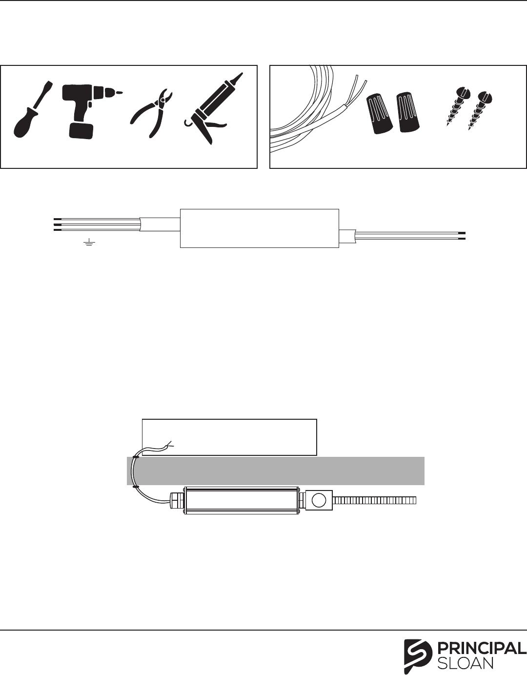
Tools required Supplies required
Screwdriver, Drill, Wire Stripper, Silicone and Gun UL Listed PTLC Cable, Wire Nuts, #8 Panhead Screws
Power Supply:
Primary side:
AC/L (Black)
AC/N (White)
Secondary side:
V+ (Red)
V- (Black/Blue)
FG (Green)
Make secondary connections:
Secondary output is 12VDC or 24VDC.
Secondary Class 2 Cables DO NOT require
conduit per NEC 2008 Articles 725.121-
130. Always seal wall penetrations
carefully to prevent water damage.
NOTE: Do not exceed 5A DC load. To minimize light loss it is
recommended to split the load equally in two parallel runs
(2.5A) of LED modules, or wire the secondary input to both
ends of the fully loaded 5A strand of LEDs
Mount power supply: Using a drill and
the #8 Panhead screws, mount the
power supply using the mounting tabs
at the bottom of the supply.
Make primary connection: A licensed
electrician is required in order to bring
conduit to the junction box and make
the primary connection.
Sign cabinet or channel letter
Power supply UL Listed
J-Box
Secondary output connection
Primary power
conduit
Wall penetration
(fill with silicone)
Attach power supply to J-box: Attach power supply(s) to
junction box using 0.5" locknut. Multiple power supplies may
be connected and configured to the same junction box.
For wet locations, use a junction box that is UL-rated for wet use.
NOTE: Operating temperature is -22º to 140º F (-30º to 60º C) therefore it is required by UL that the power supplies are spaced at least 2" (51 mm) apart side-to-side, 1"
(25 mm) end to end, and not in secondary enclosure to ensure optimal ventilation to ensure maximum lifetime of the power supply, it is highly recommended that a photo-
cell or timer be used to prevent operation during daylight hours. Do not use more modules than recommended on the product installation guide. Total amperage should
not exceed 5.0 A per power supply
0.5" (13 mm) Locknut
Primary wiring
PL-60-12-MU, Installation Guide, PS
Input: 100-277 / Output: 12 VDC
PRODUCT RETROFIT GUIDE
PAGE 5 OF 7
A Principal Industries Company
Cabinets and Channel Letters
Enclosure/Raceway Mount Power Supplies
Tools required Supplies required
Screwdriver, Drill, Wire Stripper, Silicone and Gun UL Listed PTLC Cable, Wire Nuts, #8 Panhead Screws
Make secondary connections:
Secondary output is 12VDC or 24VDC.
Secondary Class 2 Cables DO NOT require
conduit per NEC 2008 Articles 725.121-
130. Always seal wall penetrations
carefully to prevent water damage.
NOTE: Do not exceed 5A DC load for 12VDC or 4 A load for
24VDC. To minimize light loss it is recommended to split
the load equally in two parallel runs (2.5A @ 12VDC or 2.0A
@ 24VDC) of LED modules, or wire the secondary input to
both ends of the fully loaded 5A strand of LEDs
Mount power supply: Using a drill and
the #8 Panhead screws, mount the
power supply inside the channel letter,
inside the raceway, or in a separate UL
enclosure using the mounting tabs at
the bottom of the supply.
Make primary connection: A licensed
electrician is required in order to bring
conduit to the junction box and make
the primary connection.
Sign cabinet or channel letter
Power supply UL Listed
J-Box
Secondary output connection
Primary power
conduit
Wall penetration
(fill with silicone)
Power Supply:
Primary side:
AC/L (Black)
AC/N (White)
Secondary side:
V+ (Red)
V- (Black/Blue)
FG (Green)
NOTE: Operating temperature is -22º to 158º F (-30º to 70º C) (see de-rating chart at PrincipalSloan.com for higher temperature option), therefore it is recommended
that the power supplies are spaced at least 4" (102 mm) apart side-to-side, 2" (51 mm) end-to-end (some models have been approved for 2" (51 mm) and 1" (25 mm)
end-to-end), and not in secondary enclosure to ensure optimal ventilation (please see table for details). To ensure maximum lifetime of the power supply, it is highly
recommended that a photocell or timer be used to prevent operation during daylight hours. Do not use more modules than recommended on the product installation
guide. Total amperage should not exceed max. output current (full list on next page).
Installation guide, self-contained PS
Input: 100-277 VAC or 277-347 VAC / Output: 12 or 24 VDC

PRODUCT RETROFIT GUIDE
PAGE 6 OF 7
A Principal Industries Company
Cabinets and Channel Letters
Enclosure/Raceway Mount Power Supplies
NOTE: Do not insert Stik into existing sockets until ballast has been disconnected from mains and removed.
1: Turn off power from main lines. 2: Cut power and secondary lines to
the existing ballast and remove.
3: Remove old fluorescent lamps from
existing lamp sockets.
4: Insert Stik into lamp socket.
See depth chart to determine LED
direction. Depth Chart can be found at
PrincipalSloan.com
5: Using UL Listed 12-18 gauge hook-up
wire, connect gray wire (+) and white wire
(-) to the 12V power unit using wire nuts.
6: Connect hook-up wire to the
secondary output of the 12VDC power
supply.
Troubleshooting
• Check power to sign.
• Check power connection to the driver.
• Check polarity on the Direct Current side (Red+ / Black -).
• Check wire nut connections to each Stik.
New Construction Mounting Brackets
NOTE: Mounting brackets are available for new construction.
Use as a mounting base on each side of the cabinet.
This instruction sheet is meant to be used in accordance with all NEC and local
electrical codes. This document does not supersede any local, state, or national
regulations. For questions, please contact Principal Sloan at 325.227.4577 or visit
us on the web at PrincipalSloan.com
1: Mount base to each side
of the return.
2: Insert Stik onto threaded
base and adjust using wing
nut to desired position and
tighten.
Tighten wing
nut at each
end to adjust
height and
stabilize the
Stik.
LEDs may be pointed
to sign face or return
depending on depth
to face.

Rev B 2024-06-19
Customer service and technical support
PAGE 7 OF 7
principalsloan.com
325.227.4577
3490 Venture Dr., San Angelo, TX 76905
PRODUCT RETROFIT GUIDE
Cabinets and Channel Letters
A Principal Industries Company
E#341517 UL Recognized Principal Sloan LED Power Supplies
Model SKU Input voltage Input current
Output
voltage
Output
current Frequency Location rating
Energizer Series 20W
12VDC Power Supply
P-OH020-12-EC 90-305 VAC Max. 0.5 A 12 VDC 0-1.67 A 47-63 Hz Wet/Damp/Dry
Energizer Series 20W
24VDC Power Supply
P-OH020-24-EC 90-305 VAC Max. 0.5 A 24 VDC 0-0.833 A 47-63 Hz Wet/Damp/Dry
Energizer Series 60W
12VDC Power Supply
P-OH060-12-EC 90-305 VAC Max. 1.35 A 12 VDC 0-5 Amps 47-63 Hz Wet/Damp/Dry
Energizer Series 60W
24VDC Power Supply
P-OH060-24-EC 90-305 VAC Max. 1.35 A 24 VDC 0-2.5 Amps 47-63 Hz Wet/Damp/Dry
Energizer Series Threaded
100W 24VDC Power Supply
P-OH100-24-EC-T 90-305 VAC Max. 2.5 A 24 VDC 0-4 Amps 47-63 Hz Wet/Damp/Dry
Energizer Series Threaded
60W 12VDC Power Supply
P-OH060-12-EC-T 90-305 VAC
1.33 A/100 VAC,
0.65 A/230 VAC
12 VDC 0-5 Amps 47-63 Hz Wet/Damp/Dry
HE 120 W 12VDC Power Supply P-OH120-12-HE 120-277 VAC
1.2 A/120 VAC,
0.51 A/277 VAC
12 VDC 0.5-5.0 Amps 50-60 Hz Damp/Dry
HE 180 W 12VDC Power Supply P-OH180-12-HE 120-277 VAC 1.8-0.76 A 12 VDC
0.5-5.0 Amps
(per channel, 3-channel)
50-60 Hz Damp/Dry
HE 300 W 24VDC Power Supply P-OH300-24-HE 120-277 VAC 2.9-1.27 A 24 VDC
0.41-4.1 Amps
(per channel, 3-channel)
50-60 Hz Damp/Dry
HE 60 W 12VDC Power Supply
*
P-OH060-12-HE 110-277 VAC
0.61 A/100 VAC,
0.27 A/277 VAC
12 VDC 0.5-5.0 Amps 50-60 Hz Damp/Dry
HE 96 W 24VDC Power Supply
*
P-OH096-24-HE 110-277 VAC
0.98 A/100 VAC,
0.42 A/277 VAC
24 VDC 0.41-4.1 Amps 50-60 Hz Damp/Dry
Universal 100 W 24VDC
Micro-Driver Power Supply
P-OH100-24-MD 120-277 VAC
0.9 A/120 VAC,
0.39 A/277 VAC
24 VDC 0-4.0 Amps 50-60 Hz Damp/Dry
Universal 60 W 12VDC
Micro-Driver Power Supply
P-OH060-12-MD 100-277 VAC Max. 0.7 A 12 VDC 0-5.0 Amps 50-60 Hz Damp/Dry
Voltage Drop Chart
Voltage (VDC)
Current
(A)
Power
(W)
Wire Gauge
24 22 20 18 16 14 12 10 8 6 4 2
12
0.5 6 40 64 100 160 250 400 650 1000 1600 2550 4000 6500
1.0 12 20 32 50 80 125 200 325 500 800 1275 2000 3200
1.5 18 13 22 33 55 85 132 215 330 525 850 1400 2150
2.0 24 10 16 25 40 62 100 160 250 400 650 1000 1600
2.5 30 8 13 20 32 50 80 125 200 325 500 800 1290
3.0 36 7 11 17 26 42 66 110 165 265 425 675 1100
3.5 42 6 9 14 23 36 58 90 145 230 365 575 925
4.0 48 5 8 13 20 32 50 78 125 200 320 500 800
4.5 54 4 7 11 18 28 45 70 110 175 280 450 720
5.0 60 4 6 10 16 25 40 65 100 160 255 400 640
24
0.5 12 80 128 200 320 500 800 1300 2000 3200 5100 8000 13000
1.0 24 40 64 100 160 250 400 650 1000 1600 2550 4000 6400
1.5 36 26 44 66 110 170 264 430 660 1050 1700 2800 4300
2.0 48 20 32 50 80 124 200 320 500 800 1300 2000 3200
2.5 60 16 26 40 64 100 160 250 400 650 1000 1600 2580
3.0 72 14 22 34 52 84 132 220 330 530 850 1350 2200
3.5 84 12 18 28 46 72 116 180 290 460 730 1150 1850
4.0 96 10 16 26 40 64 100 156 250 400 640 1000 1600
NOTE: All distance denoted in feet.
