
Guidelines for Design of
Small Public Ground Water
Systems
Division of Drinking and Ground Waters
June 2023

Guidelines for Design of Small Public Ground Water Systems
June 2023
Page 2 of 77
Foreward
This publication has been prepared as a guide for professional engineers and water supply specialists engaged in
the design or development of small public water systems (non-community and communities serving less than
500 service connections) using only ground water, which is not required to treat for a primary contaminant with
a maximum contaminant level or a contaminant with a health advisory level (HAL). The objective here is to
ensure that new or substantially modified public water system facilities, such as those for small villages,
factories, mobile home parks, office buildings, restaurants, condominiums, schools, churches, hospitals,
campgrounds, resorts, gas stations, nursing homes, golf courses, and the like will be capable of producing an
adequate supply of potable water in compliance with applicable regulations.
The following table may be used as a guide for the applicability of design guidance:
Public Water System (PWS) Description (ground water only)
Guidelines for Design of
Small Public Water
Systems
Recommended
Standards for
Water Works
All Transient PWS
X
Nontransient PWS not required to treat for a primary contaminant or
a contaminant with a HAL per OAC 3745
X
Nontransient PWS required to treat for a primary contaminant or a
contaminant with a HAL per OAC 3745
X
Community < 500 not required to treat for a primary contaminant or a
contaminant with a HAL per OAC 3745
X
Community < 500 required to treat for a primary contaminant or a
contaminant with a HAL per OAC 3745
X
Community > 500 required to treat for a primary contaminant or a
contaminant with a HAL per OAC 3745
X
The purpose of this manual is to present the requirements and procedures necessary to develop an approved
water supply system where connection to an existing public water system cannot be made at reasonable cost.
This publication includes treatment design criteria for iron, manganese, and hardness removal, which are not
required as part of OAC 3745.
The design of water systems using surface water or ground water under the direct influence of surface water is
beyond the scope of this manual. Refer to the latest edition of “Recommended Standards for Water Works” for
design criteria.
The requirements, criteria, and procedures described in this publication represent current practices of the Ohio
Environmental Protection Agency (Ohio EPA). They are subject to change whenever in the judgment of the
Agency such a change will be more effective in fulfilling its responsibility under the law.
NOTE: For sewage, a similar publication entitled, “Sewage: Collection, Treatment & Disposal Where Public
Sewers Are Not Available” may be obtained from Ohio EPA's Division of Surface Water.

Guidelines for Design of Small Public Ground Water Systems
June 2023
Page 3 of 77
Table of Contents
Foreward ...................................................................................................................................................................................... 2
Table of Abbreviations ................................................................................................................................................................. 5
Policy Statement on Infrastucture Security for Small Public Water Systems .............................................................................. 6
Statement on Alternative Water Treament Processes ................................................................................................................ 6
General .................................................................................................................................................................................... 6
Chapter 1 - Definitions ................................................................................................................................................................. 7
1.0 Public Water System (PWS) ........................................................................................................................................ 7
1.1 Types of Public Water Systems .................................................................................................................................. 7
Chapter 2 - Procedure for Establishing a Small Public Ground Water System ............................................................................ 8
2.0 General ....................................................................................................................................................................... 8
2.1 Plan Submittal Requirements ..................................................................................................................................... 8
2.2 Connection to an Existing Approved System.............................................................................................................. 9
2.3 Development of an Approved Ground Water System ............................................................................................... 9
2.4 Develop an Approved Storage System Using Hauled Water .................................................................................... 10
2.5 Plan Submittal and Information Required on Plans ................................................................................................. 10
Chapter 3 - Source ..................................................................................................................................................................... 11
3.0 General ..................................................................................................................................................................... 11
3.1 Availability of Well Water......................................................................................................................................... 11
3.2 Quality of Water ....................................................................................................................................................... 11
3.3 Well Site Approval .................................................................................................................................................... 12
3.4 Basis of Design .......................................................................................................................................................... 16
3.5 New Well Construction ............................................................................................................................................ 22
3.6 Casing Extensions ..................................................................................................................................................... 23
3.7 Approval of Existing Wells as Public Water Supply Wells ........................................................................................ 25
3.8 Pumping Tests .......................................................................................................................................................... 26
3.9 Reporting .................................................................................................................................................................. 28
3.10 Disinfection of Wells ................................................................................................................................................ 30
3.11 Sealing of Wells That Are No Longer Used or Needed ............................................................................................. 31
3.12 Standards ................................................................................................................................................................. 32
Chapter 4 - Treatment ............................................................................................................................................................... 32
4.0 General ..................................................................................................................................................................... 32
4.1 Detail Plan Approval Exemptions ............................................................................................................................. 32
4.2 Disinfection .............................................................................................................................................................. 32
4.3 Iron and Manganese Removal .................................................................................................................................. 36
4.4 Cation Ion Exchange Softening ................................................................................................................................. 46
4.5 Additional Treatment Methods ................................................................................................................................ 47
4.6 Corrosion Control ..................................................................................................................................................... 49
4.7 Waste Disposal ......................................................................................................................................................... 49
Chapter 5 - Storage .................................................................................................................................................................... 52
5.0 General ..................................................................................................................................................................... 52
5.1 Clearwell Storage ..................................................................................................................................................... 52
5.2 Ground Level Storage ............................................................................................................................................... 52
5.3 Elevated Storage ...................................................................................................................................................... 53
5.4 Hydropneumatic Tanks ............................................................................................................................................ 54
5.5 Constant Pressure Systems ...................................................................................................................................... 54
Chapter 6 - Distribution ............................................................................................................................................................. 55
6.0 Plan Submittal .......................................................................................................................................................... 55

Guidelines for Design of Small Public Ground Water Systems
June 2023
Page 4 of 77
6.1 Standards ................................................................................................................................................................. 55
6.2 Backflow Prevention and Cross-Connection Control ............................................................................................... 57
APPENDIX A - Example Well Site Map ....................................................................................................................................... 58
APPENDIX B - Suggested Water Usage Guide ........................................................................................................................... 60
APPENDIX C - Sample ODNR Well Log and Drilling Report ........................................................................................................ 63
APPENDIX D - Well Construction Worksheet for Existing Wells ................................................................................................ 65
APPENDIX E - 24-Hour Pumping Test Report ............................................................................................................................. 67
APPENDIX F - Sample ODNR Water Well Sealing Report ........................................................................................................... 73
APPENDIX G - Hauled Water System – Design Requirements ................................................................................................... 75
Figures
Figure 1 - Well Isolation Radius ................................................................................................................................................. 13
Figure 2 - Determining Storage Requirements .......................................................................................................................... 18
Figure 3 - How to Calculate Storage Requirements ................................................................................................................... 19
Figure 4 - Well Profile and Construction Form .......................................................................................................................... 24
Figure 5 - Disinfection ................................................................................................................................................................ 34
Figure 6 A & B - Disinfection with Cation Exchange Softening .................................................................................................. 35
Figure 7 - Iron Removal .............................................................................................................................................................. 37
Figure 8 - Iron and Manganese Removal (Revised) ................................................................................................................... 38
Figure 9 - Iron Removal and Ion Exchange Softening ................................................................................................................ 38
Figure 10 - Ion Exchange Softening............................................................................................................................................ 39
Tables
Table 1 - General Media Guidance ............................................................................................................................................ 42

Guidelines for Design of Small Public Ground Water Systems
June 2023
Page 5 of 77
Table of Abbreviations
ANSI American National Standards Institute
ASME American Society of Mechanical Engineers
ASTM American Society of Testing and Materials
AWWA American Water Works Association
BMP Best Management Practices
CWS Community Water System
NPDES National Pollutant Discharge Elimination System
NSF National Sanitation Foundation
NTNC Nontransient Noncommunity Water System
OAC Ohio Administrative Code
ODNR Ohio Department of Natural Resources
ORC Ohio Revised Code
PE Professional Engineer
PTI Permit to Install
PUCO Public Utilities Commission of Ohio
PVC Polyvinyl Chloride
PWSID Public Water System Identification Number
TNC Transient Noncommunity Water System
WSC Water System Council

Guidelines for Design of Small Public Ground Water Systems
June 2023
Page 6 of 77
Policy Statement on Infrastucture Security for Small Public Water
Systems
Recent events in the United States and abroad have made it clear that increased security for public water systems
is imperative. Review of public water system security infrastructure and practices has shown an industry-wide
vulnerability to intentional acts of vandalism, sabotage and terrorism. Protection from these types of threats
must be integrated into all design considerations. Security measures are needed to help ensure that public water
suppliers attain an effective level of security, no matter how small the water system. Design considerations need
to address physical infrastructure security and facilitate security related operational practices and management
controls. All public water supplies need to identify and address security needs in design and construction for
new projects and for retrofits of existing drinking water systems.
Appropriate design measures for small water systems include the following:
A. Controlling access and installing fences and locks for all drinking water treatment facilities and
vulnerable areas (e.g., wellheads, hydrants, manholes, pumphouses, storage tanks).
B. Installing locks on all entry gates and doors and installing alarms to indicate unauthorized entry. Do not
leave keys in equipment or vehicles at any time.
C. Installing adequate lighting around wells, pumphouses, treatment facilities and parking areas.
D. Locking monitoring wells, securing vents by moving them inside or providing vandal resistant screens
and fencing.
E. Cyber security should be considered for all remotely controlled equipment, ensuring software is up to
date when applicable.
Statement on Alternative Water Treament Processes
General
This revision to the “Guidelines for Design of Small Public Ground Water Systems,” also referred to as the
“Greenbook,” updates Ohio EPA’s increasing familiarity with newer filter media products. It is recognized the
list of media is not all-inclusive and is dynamic. Other processes are understood to exist that may be “emerging”
or “alternative” treatment processes at this time. Alternative water treatment processes involve technologies or
proprietary products not frequently seen in small public water system design. Although not covered in this
publication, Ohio EPA recognizes many of these treatment processes have been successfully used in other
settings and will evaluate these processes at public water systems on a case-by-case basis.
Ohio EPA is in the process of developing guidance that describes in more detail the testing requirements for
alternative water treatment processes. Testing requirements can vary from minor sample collection prior to
design (to validate raw water quality applicability), to a demonstration study, up to more thorough testing on a
pilot plant basis for a sufficient time to verify satisfactory performance.
Ground water treatment plants with loading rates higher than described in this manual may be acceptable on a
case-by-case basis. It will be necessary to demonstrate to Ohio EPA that the desired water quality can be
produced under varying raw water conditions and system flow demands.
Ohio EPA considers alternative ground water treatment processes to include, but not be limited to, the following:
membrane filtration, reverse osmosis, anion exchange, ozonation, ultraviolet light inactivation, carbon filtration
adsorption, activated alumina and iron-based media. Information on pilot plant study requirements is available

Guidelines for Design of Small Public Ground Water Systems
June 2023
Page 7 of 77
on the Ohio EPA Division of Drinking and Ground Waters website. You can also contact Ohio EPA Central Office
or your District Office for more information.
Chapter 1 - Definitions
1.0 Public Water System (PWS)
A public water system as defined in Ohio Administrative Code (OAC) 3745-81-01, is a system that provides water
for human consumption through pipes or other constructed conveyances, if such systems have at least 15 service
connections or regularly serves an average of at least 25 people at least 60 days a year.; or is any water supply
system serving an agricultural migrant labor camp as defined in Section 3733.41 of the Ohio Revised Code.
1.1 Types of Public Water Systems
1.1.1 Community Water System (CWS):
A CWS has at least 15 service connections used by year-round residents or regularly serves at least
25 year-round residents.
Examples of a CWS may include, but are not limited to, cities, villages, nursing homes and mobile
home parks.
1.1.2 Nontransient Noncommunity Water System (NTNC):
A NTNC serves at least 25 of the same persons at least 6 months per year.
Examples of a NTNC may include, but are not limited to, schools, daycare centers, factories and
other places of employment.
1.1.3 Transient Noncommunity Water System (TNC):
A TNC serves an average of at least 25 persons per day for at least 60 days per year.
Examples of a TNC may include, but are not limited to, campgrounds, churches, restaurants and
rest areas.
1.1.4 Agricultural Migrant Labor Camp:
Any water supply system serving an agriculture migrant labor camp, as defined in Section 3733.41
of the ORC.
1.1.5 Exempt Water System:
To be exempt from Ohio EPA Drinking Water Regulations (ORC Section 6109.02) a system must
meet all of the following conditions:
1.1.5.1 Consist only of distribution and storage facilities and does not have any collection and
treatment facilities.
1.1.5.2 Obtain all of its water from, but is not owned or operated by, a public water system.
1.1.5.3 Does not sell water to any person as determined by the director.
1.1.5.4 Is not a carrier which conveys passengers in interstate commerce, e.g., airline, railroad,
bus line, boat line, etc.

Guidelines for Design of Small Public Ground Water Systems
June 2023
Page 8 of 77
Chapter 2 - Procedure for Establishing a Small Public Ground Water
System
2.0 General
Connection to an existing approved public water system should be given primary consideration. A ground water
system may be developed if connection to an approved existing system is impractical. Alternatively, a hauled
water system may be considered, (see Section 2.4). The owner must be aware that hauled water systems are
more susceptible to interruption of supply and may be more susceptible to contamination.
2.1 Plan Submittal Requirements
2.1.1 According to OAC 3745-91-05 (A):
No person shall begin construction or installation of a public water system or make a substantial
change in a public water system, or operate a public water system, until plans have been approved
by the Director of Ohio EPA.
Upon receipt of a proper application, the Director shall consider the need for compliance with
requirements of the Safe Drinking Water Act, and generally accepted standards for the construction
and equipping of water systems and shall issue an order approving or disapproving such plans. In
granting an approval, the Director may stipulate conditions designed to ensure that the system will
be able to meet the requirements of ORC Chapter 6109 and rules adopted under it.
2.1.2 According to OAC Rule 3745-91-01(C):
“Substantial change” means any change that affects isolation, capacity, flows, water quality, source,
distribution or treatment.
Substantial change shall include, but not be limited to, the following:
1. For distribution systems: new waterlines; replacement waterlines that change in size,
alignment or material; new tanks; modification in storage; new booster stations; changes in
pump capacity and auxiliary power. Some waterline replacements are exempt from detail
plan approval in accordance with OAC 3745-91-02.
2. For water sources: any new source or alteration in source, including connection to another
source or distribution system; any alteration in collection facilities or equipment.
3. For treatment facilities: new treatment processes, including facilities, equipment or
chemicals; changes in chemical feed capacity, feeder type, application points or sequence;
modifications to or removal of treatment processes, equipment or chemicals.
Substantial change shall not include the following:
1. For distribution systems: waterline cleaning, re-lining, repairs or like-kind replacement;
service connections; and tank maintenance.
2. For water sources: like-kind pump replacement.
3. For treatment facilities: like-kind replacement of components, as defined in OAC 3745-91-
01. If there are questions regarding if the proposed replacement meets the design criteria
previously approved or if proposed treatment meets the definition of like-kind
replacement, contact the Ohio EPA district office.

Guidelines for Design of Small Public Ground Water Systems
June 2023
Page 9 of 77
2.2 Connection to an Existing Approved System
2.2.1 Contact existing public water system(s) within an economical piping distance.
2.2.2 Determine what needs to be done to facilitate the connection to the existing system.
2.2.3 If a waterline needs to be extended to your property, plans for any new water line from the water
system to the master meter must be approved by Ohio EPA prior to construction, and the new water
lines must be owned by the existing water system before they are placed in service. A service
connection to a building or residence from the PWS owned waterline does not require a submission
of detail plans to Ohio EPA.
2.3 Development of an Approved Ground Water System
Where there is no existing public water system within economical piping distance, give consideration to the
development of a ground water system.
2.3.1 Contact the appropriate District Office of Ohio EPA’s Division of Drinking and Ground Waters to
request an evaluation of a proposed well site and to establish the requirements, design criteria and
responsibilities involved. (See the map at the end of this publication, which includes Ohio EPA
District addresses and telephone numbers.)
2.3.2 Submit a completed well site application to the District Office. The application can be found on the
Ohio EPA website.
2.3.3 Obtain a well site inspection and site approval from the director. The well site approval is valid for
two years.
2.3.4 Arrange with an Ohio EPA certified laboratory for analysis of the required parameters for new wells
after the well has been drilled and developed. A list of certified laboratories can be found on the Ohio
EPA website. Allow at least six weeks for analysis of samples. A list of required parameters
(Parameters Required for Complete Well Analysis) is included in OAC Rule 3745-9-09.
2.3.5 The well must be constructed and grouted in accordance with the construction and grouting
standards prescribed in OAC Chapter 3745-9. All wells must be grouted, including those drilled by the
cable tool method. Well construction standards can be found in Section 3.5, with requirements
specific to PVC casing noted in item 3.5.3-13. Be advised that the Ohio Department of Health Private
Water System Program maintains a registry of drilling contractors who operate in the state of Ohio.
2.3.6 Perform a pumping test (refer to Section 3.8) and collect the required samples at the conclusion.
2.3.7 Submit the pumping test and sample analyses, prior to plan approval, to the District Office for
evaluation and information regarding the treatment processes required for your proposed system
based on the sample analyses.
2.3.8 Have a professional engineer or a water supply specialist knowledgeable in design prepare plans for
the system, covering well construction, treatment, storage and distribution.
2.3.9 Submit detail plans. Construction of the treatment, storage and distribution system must not begin
until the formal approval letter is received from the director.

Guidelines for Design of Small Public Ground Water Systems
June 2023
Page 10 of 77
2.4 Develop an Approved Storage System Using Hauled Water
Hauled water systems are not recommended for community public water systems. Consult the District Office to
determine whether or not the hauled water system will be exempt from Ohio EPA regulation (see Section 1.1.5).
If the hauled water system is not exempt, plans will be required (see Appendix G ). If the hauled water system
will be exempt, the required health department and plumbing permits must still be obtained.
2.5 Plan Submittal and Information Required on Plans
Detail plans are required for a proposed water system. These should be prepared by a professional engineer or a
water supply specialist knowledgeable in system design in accordance with OAC 3745-91-03. Plans should be
submitted at least 60 days prior to the desired approval date. These plans shall contain the following, where
applicable:
2.5.1 A site map (Appendix A), drawn to scale, showing existing and/or proposed:
2.5.1.1 Property lines, ownership of land, and land use of surrounding properties.
2.5.1.2 Outlines of buildings, including those relevant to the project which are located on adjacent
properties.
2.5.1.3 Water system location.
2.5.1.4 Sewerage system location.
2.5.1.5 Well site(s) with isolation radius (radii), and showing any potential sources of contamination
and areas owned or having sanitary protection through recorded easements.
2.5.1.6 Nearby streets, driveways, and enough boundary information to locate the project.
2.5.1.7 Any expected future expansion of the project.
2.5.1.8 North arrow to show orientation.
2.5.1.9 Elevations pertinent to the design.
2.5.1.10 Location of water mains, pump stations, raw water intakes, water plant, waste disposal
facilities, and other existing or proposed parts of this system.
2.5.1.11 Locations of potential contaminant sources within drinking water source protection area,
both the inner management zone and five year time of travel area.
2.5.2 Details showing conformance with standards and requirements for:
2.5.2.1 Source (Chapter 3)
2.5.2.2 Treatment (Chapter 4)
2.5.2.3 Storage (Chapter 5)
2.5.2.4 Distribution (Chapter 6)
2.5.3 The application for detail plans on the portal replaces the Water Supply Data Sheet. Following
submittal of plans, the submitter is emailed an invoice for the plan review fee. Additional
information is located on the Ohio EPA website under the Division of Drinking and Ground Waters
website, engineering and plan approval page.
2.5.4 Specifications, project summary sheets and supporting data (e.g., well log, pumping test, etc.)
2.5.5 Other letters as appropriate such as PUCO certificate of convenience and necessity, if applicable or
additional documentation required for obtaining Water Supply Revolving Loan Account (WSRLA)
funding.
2.5.6 A title page showing, at a minimum:
2.5.6.1 The owner’s name and address.

Guidelines for Design of Small Public Ground Water Systems
June 2023
Page 11 of 77
2.5.6.2 The official name and address of the public water system.
2.5.6.3 The title of the project being submitted for review.
2.5.6.4 The public water system identification number (PWSID).
2.5.6.5 PE stamp (as required by ORC Section 4733.17 and OAC 3745-91-03).
2.5.6.6 Signature of water system owner approving the plans or a signed submittal letter from the owner
or the owner’s representative, requesting approval of the plans.
2.5.7 An asset management program (AMP) is required for new community and non-transient non-
community public water systems. The AMP must include the applicable requirements as defined in
OAC Chapter 3745-87. An AMP is also required for any existing system receiving State Revolving Loan
Funding or Drinking Water Emergency Loan Funding.
Chapter 3 - Source
3.0 General
This section overviews requirements for developing a groundwater supply source. The engineer or water system
specialist responsible for designing the groundwater system must demonstrate an adequate quantity of safe
drinking water will be available to consumers. Approval of a groundwater source will be contingent on the
quality and quantity of water supplied from the proposed well(s).
Metering of the water shall be provided for all community water systems and recommended for all
noncommunity water systems.
3.1 Availability of Well Water
The availability of an adequate well water supply is a major consideration in the selection of a well site.
Information on the availability of ground water can be obtained from the Ohio Department of Natural
Resources, Division of Soil and Water Resources, Ground Water Mapping and Technical Services Section (Tel:
614-265-6747).
3.2 Quality of Water
3.2.1 Microbiological Quality
Before any new, reconditioned or modified well is placed into potable service, the well must be
disinfected in accordance with Section 3.10. Total chlorine shall be tested and the results of the test
noted on the sample submission form. Total chlorine shall be undetectable prior to sampling for
microbiological samples. Two consecutive total coliform negative microbiological samples taken at
least 30 minutes apart shall be taken from the well. Analysis shall be performed by an Ohio EPA
certified laboratory. Ohio EPA certified laboratory list can be found on the Ohio EPA Division of
Environmental Services webpage. Additional monitoring may be required if the grouting of the well
is questionable.
If a well cannot achieve negative (safe) bacteriological samples, it may require treatment which is
beyond the scope of this manual. Contact your District Office for further guidance.

Guidelines for Design of Small Public Ground Water Systems
June 2023
Page 12 of 77
3.2.2 Chemical and Radiological Quality
Every proposed ground water source must be examined for applicable chemical and radiological
characteristics by analysis of a representative sample in a laboratory certified by Ohio EPA. Note if
contaminants are detected, then re-sampling may be required to confirm the results.
The samples for laboratory analysis must be collected at the conclusion of the pumping test
procedures and prior to initiation of the recovery period. Ohio EPA can advise on whether the well
can be approved, and on methods and types of treatment required on the basis of the results of
required analyses (see OAC 3745-9-09 (C)). Wells, with sample results exceeding maximum
contaminant levels (MCL), may require treatment beyond the scope of this manual. Contact District
Office for further guidance.
3.2.3 Secondary Standards
The presence of contaminants above the secondary maximum contaminant level (SMCL) may require
treatment.
Treatment may be required for community and non-transient non-community water systems to
remove excessive levels of iron and manganese, which cause staining of laundry and plumbing
fixtures and which give the water a mineral taste (see Chapter 4). Abnormally high amounts of
chlorides, sulfates and total dissolved solids can also make water objectionable for drinking. High
levels of sodium are a concern when serving communities with sodium restricted diets. Community
PWSs having sources with elevated levels, above 20 mg/L, of sodium are strongly encouraged to
ensure the susceptible population is informed and educated.
3.3 Well Site Approval
3.3.1 Requirements
Sites for public water supply wells must be approved by Ohio EPA before the wells are drilled or
when an existing system is designated a public water system. Contact the District Office for more
information.
3.3.2 Submittals
Submit a completed well site application, available on the Ohio EPA website, to the District Office.
NOTE: Refer to Appendix B for suggested water usage guide. Alternative methods of obtaining water
usage such as fixture counts or historical flow and pressure data may be used in certain
circumstances as described in Section 3.4.
3.3.3 Site Visit
The District Office will review the well site application and contact you to arrange for a site visit. A
representative of the system, and the selected well driller, should be present during this visit. Several
items may be discussed in the field including, but not limited to:
1. Sanitary control of isolation zone surrounding the proposed well. (See Section 3.3.5).
2. Known or suspected water quality issues.
3. Detail plan preparations.
4. Source water protection.
5. Certified laboratories for analysis.

Guidelines for Design of Small Public Ground Water Systems
June 2023
Page 13 of 77
The District Office will be available to answer questions the system representative may have
regarding the well site.
3.3.4 Site Evaluation
The owner will receive a letter from the director either approving or denying the site for the
proposed project. Additional requirements may be stipulated in the well site approval letter.
3.3.5 Isolation Standards and Well Siting Criteria
A proposed public water system well shall be located the maximum practical distance from potential
or known contamination. Unless local conditions dictate greater distances, approval of each well site
will be based on compliance with the following isolation radii and well siting criteria:
Estimated Average Daily
Water Usage (Q)
Minimum Isolation Radius from
Sources of Possible Contamination
0-2,500 gpd
2,501-10,000 gpd
10,001-50,000 gpd
Over 50,000 gpd
50 feet
(Square Root of Q) feet
(50 + Q/200) feet
300 feet
Well isolation radius will be determined in the Director’s well site approval letter and finalized in
the Director’s plan approval letter. The isolation radius can only be adjusted with an updated
Director’s plan approval letter.
Figure 1 - Well Isolation Radius
Use Figure 1 to calculate the required isolation radius. Normally, the required isolation distance
shall be rounded up to the nearest five feet.

Guidelines for Design of Small Public Ground Water Systems
June 2023
Page 14 of 77
Potential sources of contamination shall not be constructed or placed within the sanitary isolation
radius of a public water system well.
Where geological factors warrant less isolation from sources of contamination, a qualified ground
water professional’s report to that effect, together with a statement of protective measures, may be
accepted.
Where fractured bedrock or extremely porous subsoil extends to or near the surface of the ground
or where poor drainage or other unfavorable conditions are encountered, greater isolation distance
or treatment as a surface water supply may be required.
The owner of the well shall own all of the land or obtain a sanitary easement or lease of the sanitary
isolation radius of the well. Land application of sludge or manure shall not be applied within
easements. The easement or lease must meet specifications set forth in OAC Rule 3745-9-04 and
shall be recorded with the County Recorder’s Office. Any proposed change in land use within the
isolation radius requires consultation with Ohio EPA. Additionally, if proposing to use fertilizers,
herbicides, or pesticides within an easement, please consult Ohio EPA to ensure the methods used
to apply and select chemicals adequately prevent contaminants from infiltrating the well; Ohio EPA
may require additional monitoring based upon circumstances.
The well shall be adequately protected from physical damage. The installation of barriers may be
required to protect the well from vehicular traffic or other inadvertent damage.
A public water system well shall be located at least:
1. Ten feet from the foundation of any building, except within a pumphouse.
2. Fifty feet from streams and lakes.
3. Three hundred feet from a human or animal waste management facility.
4. Three hundred feet from a land application area, stockpile, storage or staging area.
5. One hundred feet from a land application area field if the waste is injected or three hundred
feet if the waste is surface applied but in no case within the sanitary isolation radius of the
well.
6. Three hundred feet from a soil absorption system handling more than ten thousand gallons
per day.
7. One thousand feet from a landfill or monofill.
8. Five hundred feet from a construction and demolition debris facility.
9. Outside of a floodway unless prior approval is obtained from the director. Casing must
terminate at least 3 feet above the 100 year flood plain level. Wells located within wetlands
may require additional permits. Contact the Division of Surface Water for more information.

Guidelines for Design of Small Public Ground Water Systems
June 2023
Page 15 of 77
A public water system well used by a community or nontransient noncommunity public water
system shall be located such that the following are not located within the proposed well's inner
management zone as determined by the system’s Source Water Assessment and Protection Plan
(SWAP):
1. Human or animal waste management facility, except a well that is used by the facility.
2. Soil absorption system handling more than ten thousand gallons per day in an area where
the Ohio EPA has determined the aquifer has a high susceptibility to contamination.
3. Land application stockpile, storage or staging area where the Ohio EPA has determined the
aquifer has a high susceptibility to contamination.
A public water system well shall be sited such that no landfill or monofill is located within the
proposed well's drinking water source protection area (5 year time-of-travel).
Other possible sources of contamination must be brought to the attention of the District
Representative and their potential effect on the proposed well evaluated by the District
Representative. Possible sources of contamination include, but not limited to:
1. Grossly contaminated (chemical or bacteriological) rivers, streams or drainage ditches.
Rivers, streams and ditches are not considered as possible sources of contamination.
2. Sewers that carry sanitary or chemical waste, or storm water or field drainage tiles.
3. Septic tanks, leaching wells or beds, privies, cesspools, surface or subsurface sand filters,
sewage force mains, or sewage treatment plants.
4. Livestock holding areas, barnyards or feed lots for which feed is brought in from another
source. Pasture land is not considered as a possible source of contamination.
5. Railroad right-of-ways in which spills may have occurred or defoliant agents may have been
applied.
6. Waste or product storage tanks (above or below ground), oil and gas production wells,
mining operations, landfills, disposal areas old or new, demolition fill areas, pipelines (gas
mains, oil mains, etc.), manufacturing facilities in the proximity of the proposed well field,
and abandoned wells which are not properly sealed.
3.3.6 Sanitary Sewers in Well Field Areas
The current Ohio EPA policy regarding sanitary sewers in a well field area is as follows:
3.3.6.1 Sanitary and combined sewers are not acceptable in well field areas; however, they may be
permitted under exceptional and unavoidable circumstances. Pressure sewers and manholes
shall not be permitted under any circumstances. In any case, sanitary and combined sewers
and associated manholes shall not be located closer than 50 feet or one-third of the isolation
radius, whichever is greater, approved for that well or specified by the Division of Drinking
and Ground Waters guidelines. Gravity sewer laterals should meet the 50 feet isolation
radius.
3.3.6.2 The Division of Drinking and Ground Waters may require quarterly or monthly bacterial and
nitrate/nitrite monitoring of each well when sanitary sewers are located within the isolation
radius.

Guidelines for Design of Small Public Ground Water Systems
June 2023
Page 16 of 77
3.3.6.3 A best management practices (BMP) program shall be implemented for sanitary sewers or
combined sewers within well field areas. Provisions shall be made for periodically pressure
testing the sewer. The sewers shall be pressure tested at a frequency determined by the
District Office, at a minimum of every five years.
3.3.6.4 Where sewers are being installed, the sewer materials shall be appropriate pressure rated
pipe and shall be pressure tested to ensure water tightness.
3.4 Basis of Design
3.4.1 Requirements
The primary well system must be capable of providing an adequate supply of water during normal
and peak usage periods. In addition, standby or alternate sources may be required in case of
emergency, pump failure, etc., as described in Section 3.4.3.
Calculate the average daily, peak daily, and peak hourly demands using factors not less than those
shown below:
1. Average Daily Demand = The estimated average daily water demand shall be determined by
using either the table provided in Appendix B or at least one year of historical water use.
Average Daily Demand may be determined by less than a year of historical data,
incorporating a safety factor. Contact your District Office Engineering Section with regard to
determining the safety factor for your system.
2. Peak Daily Demand = Average Daily Demand x 2.0, unless a lower peak demand factor is
supported by at least three years of historical daily flow data using the highest peak day to
average day ratio for the period of record.
3. Peak Hourly Demand = Average Daily Demand x 10*
(* Other sizing or design methods, such as fixture counts, conforming to documented
engineering practice standards are also acceptable alternatives. A lower peak hourly demand
factor must be supported by at least one year of continuous flow and pressure data).
Note: The capacity of the design pump cannot exceed the pumping test rate. See Section 3.8
for pumping test information.
3.4.2 Procedure
3.4.2.1 Drill Well: After the well site approval letter has been received (Section 3.3), the proposed
well may be drilled. Only water system contractors holding a valid registration from the Ohio
Department of Health may drill a well or install a pitless adapter or pitless unit for a public
water system well.
3.4.2.2 Test Pump: The well shall be pump tested to determine its capacity and to obtain water
quality samples as required. Air pumping or bailing is generally not acceptable for this test.
Static and pumping water levels and recovery rates shall be measured and recorded. See
Section 3.8 for pumping test report requirements.
3.4.2.3 Alternative: If the well does not have sufficient capacity to meet the standards of 3.4.3,
outlined below, the owner shall contact the District Office for assistance.

Guidelines for Design of Small Public Ground Water Systems
June 2023
Page 17 of 77
3.4.3 Standards
3.4.3.1 All new community water systems and noncommunity water systems with a consumption
exceeding 50,000 gpd or with a population of 500 or greater shall be capable of meeting peak
demand with the largest well out of service. Existing community water systems with only one
fully functional well will be required to have two or more wells sized in accordance with
Section 3.4.3.2 when the existing well fails or cannot substantially meet peak demand, or
when the system demand causes pressure in the distribution system to fall below 35 psi. An
acceptable alternative to a redundant well would be an emergency connection to another
public water system with adequate capacity to meet peak demand.
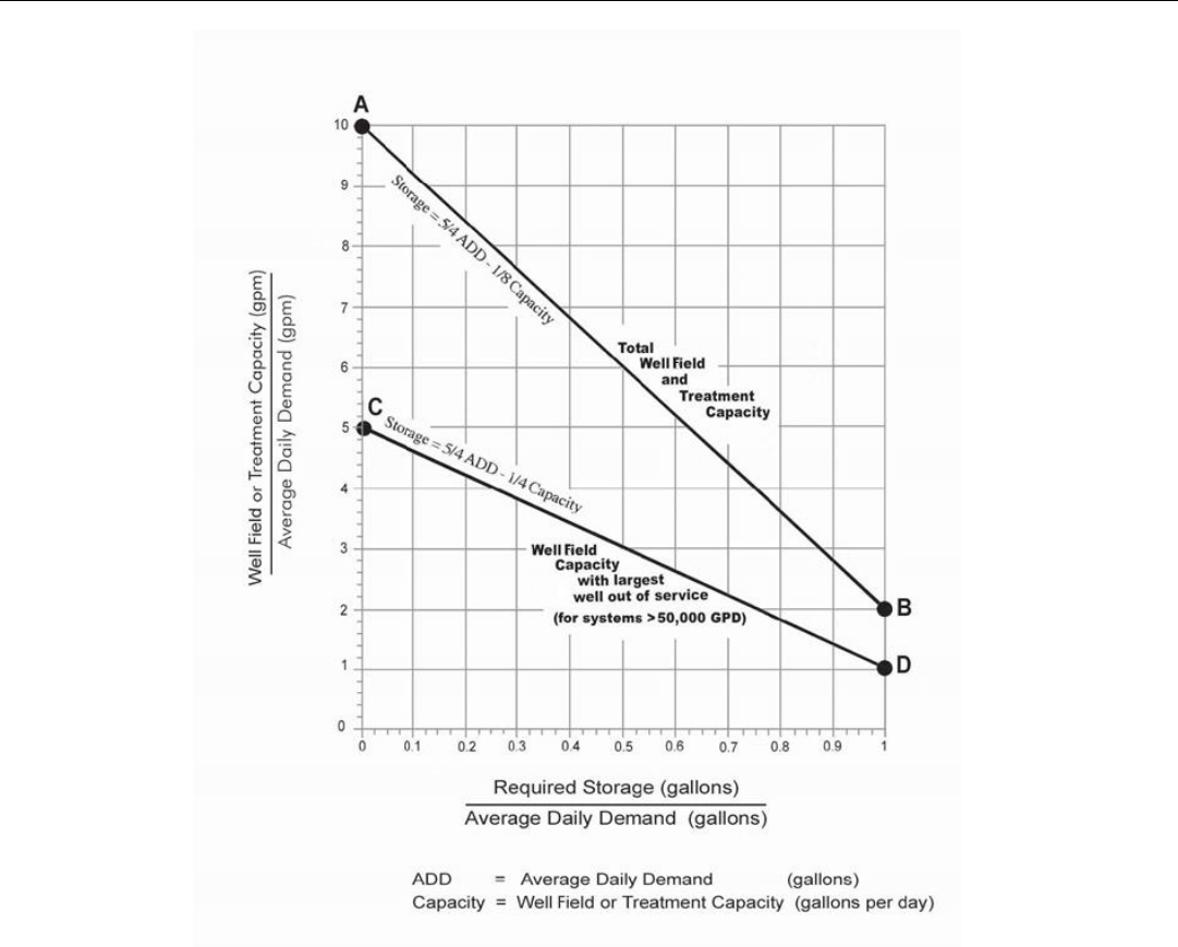
3.4.3.2 Well Field and Treatment Capacity: The capacity of the wells, well pumps and treatment
components in a hydropneumatic pressure system must be sufficient to produce water at a
rate that is ten times the average daily water demand (See Figure 2, point “A”) or approved
alternative peak hourly flow rates. Where the aquifer cannot support this withdrawal rate, a
storage tank with high service pumps may be used to meet this peak requirement, provided
that the wells, well pumps and treatment components are able to produce water at a rate that
is twice the average daily water demand. (See Figure 2, point “B”. At point “B”, one day’s
storage is required.) Please note that, at a minimum, the total well field capacity must meet
the peak daily demand (twice the average daily water demand).
In addition, the wells, well pumps and treatment components in a hydropneumatic pressure
system using over 50,000 gpd must be sufficient to produce water at a rate that is five times
the average daily water demand with the largest well or treatment unit out of service (See
Figure 2, point “C”). Where the reduced well field cannot support this withdrawal rate, a
storage tank with high service pumps may be used to meet this peak requirement, provided
that the reduced well field is able to produce water at rate that is at least equal to the average
daily water demand. (See Figure 2, point “D”. At point “D”, one day’s storage is required.)
Please note that, at a minimum, the reduced well field capacity must meet the average daily
water demand. If withdrawal is anticipated to be greater than 100,000 gallons per day, then
PWS should contact Ohio Department of Natural Resources on permitting requirements.
Figure 2 can be used to determine storage requirements. A sample problem is provided
following the graph (Figure 3). The example is solved by utilizing the graph and storage
equations. Alternative methods for estimating storage requirements may be submitted for
consideration.
Water usage values are provided in Appendix B as an aid to calculate average daily water
demand.
Guidelines for Design of Small Public Ground Water Systems
June 2023
Page 18 of 77
Figure 2 - Determining Storage Requirements

Guidelines for Design of Small Public Ground Water Systems
June 2023
Page 19 of 77
Figure 3 - How to Calculate Storage Requirements

Guidelines for Design of Small Public Ground Water Systems
June 2023
Page 20 of 77
NURSING HOME
Well #1 =
175 gpm
455 patients @ 150 gpd*
=
68,250 gpd
Well #2 =
50 gpm
15 resident employees @ 100 gpd
=
1,500 gpd
Well #3 =
50 gpm
45 non-resident employees @ 50 gpd*
=
2,250 gpd
Well #4 =
25 gpm
72,000 gpd
(50 gpm)
Total =
300 gpm
Ratio #1
=
Total Well field Capacity
=
300 gpm
=
6
Average Daily Demand
50 gpm
Ratio #2
=
Well field Capacity with Largest Well Out-of-Service
=
125 gpm
=
2.5
Average Daily Demand
50 gpm
From the Graph:
Required Storage (gallons)
= 0.62
Average Daily Demand (gallons)
Therefore:
Required Storage = 0.62 x Average Daily Demand = 0.62 x 72,000 gallons = 44,640 gallons
*values obtained from water usage table in B

Guidelines for Design of Small Public Ground Water Systems
June 2023
Page 21 of 77
Example (solve by using the equations)
NURSING HOME
Well #1
=
175
gpm
=
252,000
gpd
455 patients @ 150 gpd*
=
68,250
gpd
Well #2
=
50
gpm
=
72,000
gpd
15 resident employees @ 100 gpd*
=
1,500
gpd
Well #3
=
50
gpm
=
72,000
gpd
45 non-resident employees @ 50 gpd*
=
2,250
gpd
Well #4
=
25
gpm
=
36,000
gpd
Total
72,000
gpd
Total
=
300
gpm
=
432,000
gpd
Total
=
125
gpm
=
180,000
gpd
(without largest well)
Total Well field and Treatment Capacity
(Equation #1)
Storage Requirement
=
5/4 x ADD – 1/8 x capacity
(5/4) (72,000) – (1/8)(432,000)
90,000 – 54,000
36,000 gallons
Well field Capacity with Largest Well Out-of-Service
(Equation #2)
Storage Requirement
=
5/4 x ADD – 1/4 x capacity
(5/4) (72,000) – (1/4)(180,000)
90,000 – 45,000
45,000 gallons
Conclusion: Storage Requirement = 45,000 gallons
*values obtained from water usage table in B

Guidelines for Design of Small Public Ground Water Systems
June 2023
Page 22 of 77
3.5 New Well Construction
3.5.1 Requirements
Well construction shall be such as to prevent contamination of the water and of the water-bearing
formation by either surface or subsurface sources (OAC Rule 3745-9-05).
3.5.2 Procedure
Wells shall be drilled, constructed, grouted and developed in accordance with Ohio EPA’s Water Well
Standards (OAC Rule 3745-9).
3.5.3 Standards
The most recent edition of Ohio EPA’s Water Well Standards (OAC Chapter 3745-9) applies to all well
construction and should be consulted for specific information. General criteria, applicable to all
wells, are as follows:
1. Minimum casing diameter is 5 inches.
2. Well casing height above finished grade shall be at least 12 inches and at least 12 inches above
the well house floor or concrete apron surface.
3. Solid, watertight casing shall extend at least 25 feet below ground surface.
4. Minimum grout depth shall be 25 feet below ground surface (OAC Rules 3745-9-06 & 07).
5. A well cap shall be provided. Electrical conduit connections on the well cap shall be threaded or
sealed to prevent the entrance of insects and water. Well cap shall conform to ‘Water System
Council Pitless Adaptor Standard PAS-97’ or with an alternative standard acceptable to the
director. In circumstances where an alternative well cap is required based upon the well
construction or geologic setting, the alternative well cap must be approved by the director prior
to installation.
6. The well shall be provided with a downturned screened vent. Well vents that are integral with
the well cap are acceptable so long as they are screened and face downward. When vertical
turbine pumps are used, access for water level measurements must be provided.
7. Pitless adaptors or pitless units shall be lead free and conform to “Water Systems Council Pitless
Adaptor Standard PAS-97” or with an alternative standard acceptable to the director.
8. Well screen shall be installed where the geological formations are unconsolidated or
incompetent.
9. A check valve or foot valve should be provided within the drop pipe.
10. A submersible well pump shall neither have a mercury seal, nor shall any other components of
the well construction contain mercury.
11. Each well shall be provided with a smooth nose (no threads on spigot) sample tap for collecting
raw water samples. The sample tap can be located in a valve pit or other location which is
accessible and protected from freezing. Commercial sampling hydrants may be considered.
The sample tap shall be located prior to any pressure tanks or treatment units and shall allow
for collection of a representative ground water sample from each well.
12. Each well is to be provided with a means to isolate it, sample it and pump it to waste while
keeping all remaining wells in service. Yard hydrants at the wellhead may be suitable for
sampling and pumping to waste. Sanitary yard hydrants, if used, must conform to OAC Rule
3745-95-09.
13. Well casing shall conform to the following:

Guidelines for Design of Small Public Ground Water Systems
June 2023
Page 23 of 77
Steel [See OAC Rule 3745-9-05]
Minimum thickness
Pipe specification
Joint specifications
PVC [See OAC 3745-9-05]
Minimum SDR
Pipe specification
Joint specifications
The use of PVC casing is generally not approved for wells near underground fuel storage,
known soil contamination or other sources of chemicals that can degrade and permeate PVC.
14. The water service pipe installed below ground, between the well and the treatment plant, shall
be maintained under system pressure at all times. A check valve or backflow prevention
assembly shall not be installed between the pitless device and the pressure tank.
15. The water service pipe installed below ground, between the well and the treatment plant or
distribution system, shall be sufficiently buried to prevent it from freezing (typically 4 feet).
16. The water service pipe installed below ground, between the well and the treatment plant or
distribution system, shall be certified for potable water use by either the National Sanitation
Foundation (NSF) or American Water Works Association (AWWA).
17. The “Well Profile and Construction Form” (Figure 4) is an illustration of well terminal
development and includes most specifications needed for plan approval. This form should only
be used for single cased wells with submersible pumps and pitless adaptors. Other well
configurations (gravel packing, vertical turbine pumps, etc.) shall have a plan submitted
showing the actual construction of the well.
3.6 Casing Extensions
If an extension to an existing well casing is needed to meet the required height above finished grade, a
below grade bolted steel coupling may be used. Such couplings may be used to join similar or dissimilar
materials or sizes. Bolted steel couplings used for this purpose must conform to the following criteria:
1. Conform to ANSI/AWWA Standard C219 Bolted, Sleeve-Type Couplings for Plain-End Pipe", catalog
number 43219.
2. Have a collar with the same or better strength and rigidity of the well casings being joined together.
3. Be composed of a cast steel unit joined by a minimum of four stainless steel bolts spaced uniformly
around the circumference of the coupling.
4. Provide for the well casing to extend at least 2.5 inches into the throat of the coupling. Ensure that the
coupling is centered over the joint.

Guidelines for Design of Small Public Ground Water Systems
June 2023
Page 24 of 77
5. A connection to a well casing that is made above ground shall be installed through the following
methods:
a. Threaded connection.
b. Welded connection.
c. Bolted flanges with rubber gaskets at twelve inches or greater above ground surface.
d. Extension of the casing at least 0.5 inch into the base of a pump mounted on and sealed to a
concrete pedestal.
Figure 4 - Well Profile and Construction Form

Guidelines for Design of Small Public Ground Water Systems
June 2023
Page 25 of 77
3.7 Approval of Existing Wells as Public Water Supply Wells
3.7.1 Requirements
Existing private wells, unapproved wells or non-potable wells, to be converted into public water
supply wells shall meet the same requirements and standards as a new well. In addition, assurance is
required that the well has been properly constructed and that the well is in satisfactory condition.
3.7.2 Detail Plan Approval Exemptions
Water systems newly discovered or re-opened after temporarily closing and meeting the definition of
a public water system in OAC Rule 3745-81-01, are exempted from obtaining plan approval for wells if
all of the following conditions are met:
1. A complete well analysis (including total coliforms count and possibly nitrate) is submitted and
demonstrates acceptable water quality, or a variance is granted in accordance with OAC Rule
3745-9-02, except in the following two circumstances:
1.1. Community or nontransient noncommunity public water systems that have been closed for
less than three years;
1.2. Transient noncommunity public water systems that have been closed for less than five
years.
2. A well meeting minimum casing depth or casing height standards, contained in OAC Chapter
3745-9 as documented by the Director,.
3. All well siting requirements are met in accordance with OAC Rule 3745-9-04..
3.7.3 Procedure
Follow the same procedure as for new well approval. In addition, a water system contractor holding a
valid registration from the Ohio Department of Health shall inspect the well for acceptability
regarding:
1. Casing condition.
2. Total cased depth.
3. Total well depth.
4. Length and depth of the well screen(s).
5. Upper terminal development including the pitless installation device, grouting, venting, water
tight well cap and freeze protection for the discharge line. In addition, a well log and/or a well
construction work sheet (see Appendix C and Appendix D) must be completed and submitted.
3.7.4 Standards
1. Corrosion: The casing shall be free of excessive corrosion.
2. Casing Depth: The cased depth shall be at least 25 feet unless otherwise approved.
3. Pitless Installation Device: The pitless installation device shall conform to National Sanitation
Foundation or Water System Council Standards and be free of defects which could lead to
leakage.
4. Freeze Protection: The pitless installation device and discharge line shall be installed at sufficient
depth (normally about 4 feet) below ground surface to avoid freezing.

Guidelines for Design of Small Public Ground Water Systems
June 2023
Page 26 of 77
3.8 Pumping Tests
A pumping test is required to determine the amount of water that can be safely withdrawn from the well for an
indefinite period of time. The pumping test shall be used to determine the specific capacity of the well at the
anticipated permanent design pumping rate for all high use wells intended to serve as a source to a community
public water system. There are three variations of the pumping test based upon whether the well is classified as
low, medium or high use as explained in the table below.
Classification
Estimated Average Daily Demand of the Well (gallons per day)
Low use
0 - 10,000
Medium use
10,001 - 100,000
High use
greater than 100,000
3.8.1 Pumping Test Rates
Acceptable pumping tests for low, medium or high use classification are as follows:
1. For low or medium use wells, the pumping test shall be conducted at a constant rate for a period
of at least normal operation either at the peak hourly demand, or at least 1.5 times the anticipated
permanent design pumping rate whichever is greater. If the well cannot sustain peak hourly
demand, the pumping test shall be conducted at a minimum of 1.5 times the anticipated design
pumping rate.For a community water system well, the duration of the constant rate pumping test
shall be no less than twenty-four hours.
2. For all high use wells, a step-drawdown test shall be conducted, followed by a constant rate
pumping test.
a. The step-drawdown test shall be used to obtain sufficient hydrogeologic information to
design an appropriate constant rate pumping test for the well. The step draw-down test
shall, at a minimum conform to the following:
i. Consist of three or more steps of progressively increasing pumping rates.
ii. One step shall be performed at the anticipated permanent design pumping rate.
iii. Each step shall be of approximately equal duration.
iv. Each step shall be performed at a constant pumping rate for no less than forty-
five minutes.
b. The constant rate pumping test shall be conducted for at least twenty-four hours at a
pumping rate of at least 1.5 times the anticipated permanent design pumping rate. The
constant rate pumping test shall not commence until the water level has recovered to at
least ninety percent of the drawdown caused by the step-drawdown test or twenty-four
hours after the completion of the step-drawdown test, whichever comes first. For high
use wells, all pumping tests shall include water level measurements from observation or
surrounding wells.
3.8.2 Reduced Rate Pumping Test
For low, medium or high use wells, the constant rate pumping test may be conducted at a lower
pumping rate if it is believed pumping the well at 1.5 times the anticipated permanent pump design
rate will be excessive, will not be possible, or will have adverse effects on the long-term performance
of the well or aquifer. The test may be conducted at a lower pumping rate if the following criteria are
met:
1. The constant rate pumping test is conducted at no less than 1.2 times the pump design rate.

Guidelines for Design of Small Public Ground Water Systems
June 2023
Page 27 of 77
2. A demonstration is provided that supports the reasoning for a lower pumping rate that even
under adverse conditions, including but not limited to severe drought, the well will likely be able
to supply water at the anticipated permanent design pumping rate over the anticipated functional
life of the well.
Regardless of well classification, the capacity of the design pump may not exceed the pumping test
rate. The capacity of the permanent pump must be equal to or less than the constant pumping test
rate.
NOTE: It is recommended that a person with demonstrated competency perform the respective
pumping test or aquifer test.
3.8.3 Sampling
Samples shall be collected and analyzed from a public water system well for contaminants at the
conclusion of the constant rate pumping test, and prior to initiation of the recovery period. The list of
contaminants may contain inorganics, radiologicals, synthetic organic chemicals (SOCs), volatile
organic compounds (VOCs), Per- and polyfluoroalkyl Substances (PFAS), and bacteria. The
contaminants required for each type of public water system are listed in the Appendices of OAC Rule
3745-9-09.

Guidelines for Design of Small Public Ground Water Systems
June 2023
Page 28 of 77
3.9 Reporting
The following records are to be included with detailed plan submission:
3.9.1 Well Logs
A well log is to be recorded with the Ohio Department of Natural Resources (ODNR) by the driller at
the time the well is drilled. A copy of a properly filed ODNR well log must be submitted to Ohio EPA
as part of the detail plans for a new well.
Copies of existing well logs may be obtained from the Water Wells Database provided by ODNR.
Contact ODNR, Division of Geological Survey, by e-mail at geo.survey@dnr.ohio.gov or by phone at
(614) 265-6576 with questions concerning the water well database.
3.9.2 Pumping Test Report
A report shall be submitted which includes the pumping tests with their results, interpretations, and
conclusions. For all wells, the pumping test report shall include items in 1-8 at minimum:
1. Date and times of starting through ending pumping test.
2. Pumping rate and depth at which the pump used for the test was set.
3. A data table for each well used to observe the drawdown and recovery water level
measurements, showing the time after the pump test started and the corresponding water level
measurements to the nearest 0.1 foot.
Water level measurements shall be at these time intervals:
Time after Pumping Test Started
(minute)
Time Interval Between
Measurements (minute)
0-15
16-60
61-120
121-180
181-300
Greater than 300
1
5
10
20
30
60
4. Specific capacity of the well at the tested pumping rates.
5. For high use wells only, the specific capacity of the well at the anticipated permanent design
pumping rate after drawdown has stabilized.
6. Anticipated permanent pump setting depth (in feet below ground).
7. Height above ground (in feet) of the water level measurement reference point.
8. Water level measurements must be taken immediately after termination of the constant rate
pumping test at time intervals of five minutes for the first hour and every thirty minutes
thereafter until the water level has recovered to at least ninety percent of the drawdown caused
by the pumping test.
1. In addition to the requirements 1 through 8 listed above, a high use water system well
pumping test report shall also include:
a) A map showing the location of the pumping wells and the location of other
wells used to observe drawdown. The map shall, at a minimum, include the
names of the wells as used in the report and the distance between the pumping
well and other wells used to observe drawdown.

Guidelines for Design of Small Public Ground Water Systems
June 2023
Page 29 of 77
b) Graphs plotted on semi-logarithmic graph paper showing the drawdown
measurements on the arithmetic scale and time on the logarithmic scale.
Graphs must be submitted for the pumping well and any other wells used to
observe drawdown and recovery during the pumping test.
c) Graphs plotted on semi-logarithmic graph paper showing the recovery
measurements on the arithmetic scale and time on the logarithmic scale.
Graphs must be submitted for the pumping well and any other wells used to
observe drawdown and recovery during the pumping test.
d) Arithmetic graphs showing all water-level data collected during the pumping
test and recovery period from the pumping well and all observation wells.
9. If the high use well is part of a multiple-well system the report shall also include documentation
demonstrating:
1. The well can supply water at the anticipated permanent design pumping rate while at
minimum maintaining the operational capacity of the well field and without degrading
the water quality of any well in the well field.
2. Analyses of the effects of interference drawdown from other wells owned by the PWS, as
well as other high capacity wells not owned by the PWS. Operational practices and the
potential to cause degradation of water quality at the well field should also be considered
when establishing a permanent design pumping rate for a new PWS well.

Guidelines for Design of Small Public Ground Water Systems
June 2023
Page 30 of 77
3.10 Disinfection of Wells
3.10.1 Requirements
All wells shall be properly disinfected by chlorination before being placed into service. OAC Rule
3745-9-08 specifies well disinfection procedures and should be consulted; however, a summary is
provided below.
3.10.2 Procedure
1. Disinfectant shall be slowly poured into the well by wetting the inside casing circumference,
drop pipe and electrical cable.
2. Disinfectant concentration in the water column shall be initially at least one hundred
milligrams per liter chlorine. AWWA specification, C654-13, can be consulted to determine the
necessary amount of sodium or calcium hypochlorite needed. If using unscented bleach, the
following formula can be used:
(R)2(D)(0.000272) = gallons of bleach containing 6% sodium hypochlorite
R = radius of the well in inches
D = depth of water in the well in feet
3. Water in the well shall be agitated or surged to ensure even dispersal of the disinfectant
throughout the entire water column. Recirculating water back into the well casing from an
outside spigot may distribute chlorine throughout the water column if the well pump is located
at the bottom of the well.
4. Cap the well and allow it to stand at least eight hours.
5. After disinfection, a well shall not supply water for human consumption until it has been found
to be microbiologically safe. Total coliform samples shall be collected at least eight hours after
disinfection and after all residual chlorine is completely flushed from the well. Total chlorine
shall be tested and the results of the test noted on the sample submission form. Total chlorine
shall be undetectable before total coliform sampling for microbiological samples. Two
consecutive total coliform samples, at least thirty minutes apart, must be total coliform negative
before the well can supply water for human consumption. It is preferred the samples be
collected twenty-four hours apart. An Ohio EPA certified laboratory must be used for bacterial
analysis.
6. If any of the bacterial samples taken from the well in step 5 are reported as total coliform-
positive (unsafe), repeat step 1 through step 5.
7. If the water is reported as total coliform positive (unsafe) after repeating the procedure two
times, contact the District Office.
EXAMPLE
6 inch diameter well
40 feet of water in the well
(3)
2
(40)(0.000272) = 0.097 gallons (approximately 0.1 gallons, or 1.5 cups)
Therefore: 0.1 gallons (1.5 cups) of bleach containing 6% sodium hypochlorite will
establish a chlorine residual of 100 mg/L in a 6-inch well that has 40 feet of water.

Guidelines for Design of Small Public Ground Water Systems
June 2023
Page 31 of 77
NOTE: When calcium hypochlorite is used for disinfection, the tablets or granules shall be completely
dissolved in water prior to placement into the well.
Sodium hypochlorite solution with fragrance additives shall not be used for disinfection.
3.11 Sealing of Wells That Are No Longer Used or Needed
3.11.1 Requirements
A well or dry hole whose use has been permanently discontinued, shall be properly sealed. A test
hole that is not converted into a well upon completion of testing shall also be properly sealed.
Sealing shall be in accordance with OAC Rules 3745-9-10 and 3745¬-9-07 and “The State of Ohio
Regulations and Technical Guidance for Sealing Unused Water Wells and Boreholes.”
3.11.2 Procedure
Engage a qualified ground water professional, engineer or Ohio Department of Health registered
well driller familiar with proper sealing procedures to perform or supervise abandonment of the
well. The sealing procedure from OAC Rule 3745-9-10 for a non-artesian well that is constructed
through a single aquifer is summarized below:
1. All obstructions shall be removed, including the pump and related equipment, drop pipe,
pitless adapter, suction line, trash or other debris.
2. The casing shall be removed, ripped or perforated. Casing shall be removed if the annular
seal is inadequate or water is flowing from around the outside of the casing. If none of these
conditions are present the casing may be left intact or in-place with prior approval of the
District Office.
3. If microbiological growth is present, the well shall be disinfected with sodium hypochlorite
or calcium hypochlorite to achieve at least 50 mg/L total chlorine in the water column.
4. The well can be either entirely filled with bentonite or it can be filled with clean and
disinfected sand or gravel in the bottom followed by a bentonite cap. If sand or gravel is to
be used then it may be placed no higher than the top of the aquifer or 25 feet below the
ground surface, whichever is lower.
Coarse grade bentonite can be used to seal wells that are larger than 4 inches in diameter
and less than 200 feet deep. Pelletized bentonite can be used to seal wells that are larger than
4 inches in diameter and less than 100 feet deep. Wells that are either more than 200 feet
deep or less than 4 inches in diameter will require special bentonite placement and the
District Office should be consulted.
If the casing is to be removed, the sealing material and grout shall be placed concurrently
with casing removal.
5. After the sealing material and grout have been placed into the well, the grout shall cure a
minimum of twelve hours to assess whether any settling of the sealing material has
occurred. If settling has occurred, additional grout shall be placed into the well.
6. Casing shall be removed to a depth of at least 3 feet below ground surface. The remaining
hole should be filled with clean clay.
7. Obtain, complete and submit a uniquely numbered well sealing report to the Ohio
Department of Natural Resources, Division of Soil and Water Resources. Also, submit a copy
to the Ohio EPA District Office. A sample well sealing report is included in Appendix F.

Guidelines for Design of Small Public Ground Water Systems
June 2023
Page 32 of 77
3.12 Standards
Well sealing needs to be done in such a way that there can be no vertical movement of water either within the
well borehole or in the annular space around the well casing.
Chapter 4 - Treatment
4.0 General
This section discusses disinfection, iron and manganese removal, and ion exchange softening. Any proposed
treatment must conform to the guidelines of this publication.
Upon evaluation of chemical, microbiological and radiological test results, the District Office shall determine the
need for additional treatment.
A separate room or building should be used for water treatment chemicals and equipment and should be
accessible only to authorized personnel.
All chemicals, substances and materials added to or brought in contact with water or intended to be used in a
public water system or used for the purpose of treating, conditioning, altering or modifying the characteristics of
such water shall conform with the ANSI/NSF standards 60 and 61.
4.1 Detail Plan Approval Exemptions
Ground water noncommunity public water systems serving less than 250 persons are exempt from obtaining
prior plan approval for the installation of cation exchange softeners and cartridge filters if all of the following
conditions are met:
4.1.1 The public water system submits the following information, in accordance with OAC Rule 3745-91-02
(G):
1. The equipment is certified to meet ANSI/NSF/CAN standards stated in OAC Rule 3745-83-01(D).
2. For cation exchange softeners, the number and size of units, the system well capacities, the
loading rate, the blending information and the method of brine disposal.
3. For cartridge filters, the number of units, the system well capacities, the manufacturer and
model number, whether the units are cleanable or disposable, and the manufacturer's capacity
recommendation.
4. The PWS does not have a raw water nitrate result greater than 5 mg/L or an inorganic result of
greater than 80% of the MCL for applicable contaminants as defined in OAC Chapter 3745-81.
4.2 Disinfection
4.2.1 Requirements
All community public water systems and major noncommunity water systems (those serving 1,000 or
more persons for any 60 days out of the year) must provide disinfection. Noncommunity public water
systems (with storage or large or complex distribution systems), not required to provide disinfection,
should consider the installation of a chlorination system. Gaseous chlorination should not be
considered for small water systems and is not covered by this manual.
A public water system may be encouraged to install a chlorination system if its distribution system is
determined to be the source of a persistent total coliform-positive issue. When a chlorination system
is primarily used to eradicate total coliform bacteria in the distribution system, the public water
system may not be required to provide detention time. A chlorine residual will have to be measured
daily from the distribution system to ensure the chlorine concentration is maintained at a level to

Guidelines for Design of Small Public Ground Water Systems
June 2023
Page 33 of 77
adequately remove total coliform bacteria. Chlorination systems primarily used for the removal of
total coliform bacteria are usually installed for temporary use.
4.2.2 Design Procedure for Hypochlorite Feed System
1. Equipment: A hypochlorinator feed system consisting of a solution tank and a small diaphragm
pump with a four-way valve placed on the discharge side of the pump or a peristaltic type pump
is used to inject a chlorine solution into the water. Injection ports should be 45 degrees from the
bottom of the pipe and protrude 1/3 of the pipe diameter into the pipe. The pump must be
selected to normally operate in the middle third of its range.
Feed Pump
=
Well pump
x
Required
x 1440
Solution
Output
Output Rate
Dosage
÷
Strength
(GPD)
(gpm)
(ppm)
(ppm)
Tanks and appurtenances must be durable, corrosion-resistant material, protected against
freezing and readily cleanable. The tanks must be provided with a cover and a means to measure
the daily usage in the tank.
Redundancy of chlorination system components shall be provided for community and major
noncommunity water systems, any system installing chlorination for ground water rule
compliance, or for systems as required by the Director. Redundancy may include additional
inline pumps, spare pump(s) in storage and/or additional pump components. Contact the
District Office for more information.
2. Chlorine Solution: Chlorine solution can be prepared by one of the following methods:
a) Mix one gallon of sodium hypochlorite (5-1/4% chlorine) with 4 gallons of water in the
solution tank. This will provide a solution of approximately 1% active chlorine (10,000
ppm). Three pints of commercial 15% sodium hypochlorite can be substituted for the
gallon of sodium hypochlorite.
b) Dissolve one-half pound of dry calcium hypochlorite into 4-1/2 gallons of water using
the solution tank. This will provide a solution of approximately 1% active chlorine.
3. Installation: Install hypochlorinator pumps to operate when the well pump operates.
Alternatively, a flow-paced feed system may be required depending upon the system design.
The injection point should be after any softener (if provided) and before the pressure and
detention tanks. If the chlorinator is placed before the softener, compatibility between the
softener resin and chlorine must be confirmed. Ideally, the chlorine concentration upstream of
the softening system should be less than 1 mg/L.
Figures 5 and 6 illustrate typical chlorination installations.
4.2.3 Standards
1. Detention time: The detention tank must be sized and designed to permit a full 30 minutes for
disinfection contact time. Chlorine contact time provided for iron oxidation may be credited
toward the 30 minute minimum chlorine disinfection contact time. This shall be maintained
prior to distribution. The chlorine contact tank should be baffled to minimize short circuiting,
preferably with a large length to width ratio (i.e., 30:1).

Guidelines for Design of Small Public Ground Water Systems
June 2023
Page 34 of 77
An alternative to providing 30 minutes of disinfection contact time is to provide a minimum 4.0
log inactivation of viruses. Contact your District Representative for guidance.
A pressure tank that is connected to the main line by a single pipe is considered as floating on the
system. This arrangement cannot be considered as providing chlorine contact time. Separate
inlet and outlet pipes may be used to achieve contact volume.
2. Chlorine Content: During the detention period, a minimum free chlorine residual of 0.5 mg/L
should be maintained.
In the distribution system a minimum free chlorine residual of 0.2 mg/L or a minimum combined
chlorine residual of 1.0 mg/L shall be maintained.
The feed rate (pump setting) necessary to obtain the desired residual can be determined by
experimentation using a digital DPD (N, N-Diethyl-p-Phenylene Diamine) chlorine test kit. The
test kit must provide an electronic measurement of the color development and have a digital
display of the result. The DPD test kit must have a method detection limit of 0.1 mg/L.
CAUTION: Hypochlorites are strong oxidants. Avoid storing oil or other combustible materials in the
chlorination area.
Figure 5 - Disinfection

Guidelines for Design of Small Public Ground Water Systems
June 2023
Page 35 of 77
Figure 6 A & B - Disinfection with Cation Exchange Softening
Notes:
1. The piping between the well and the treatment system (typically a buried pipe) shall be
maintained under system pressure at all times (OAC Rule 3745-9-05). A check valve or
backflow preventer shall not be installed between a pitless adapter or pitless unit and the
pressure tank.
2. The location of the pressure tank has to be considered. Installing it as the first component will
provide for attenuation of potential water hammer produced by the well pump. Installing it at
an intermediate location or as the last component will provide a defined flow rate, as
generated by the well pump, for all the treatment or chemical feed equipment located before
it.
3. Chemicals can be injected into the water system by using a simple flow switch (Figure 6. A) or a
flow paced system (Figure 6. B). The flow switch uses preset thresholds to control when the
dosing pump will operate; a fixed amount of chemical will be injected into the water system
when using a flow switch to control the dosing pump. When using a flow paced system,

Guidelines for Design of Small Public Ground Water Systems
June 2023
Page 36 of 77
typically signals from a flow meter will alert the dosing pump to increase or decrease the
amount of chemical injected into the water system.
4.3 Iron and Manganese Removal
4.3.1 Treatment Requirements
1. New community water systems shall provide treatment for removal of:
a) Iron to meet the secondary maximum contaminant level (SMCL) of 0.3 mg/L as set forth
in OAC Rule 3745-82-02 when the level of iron in water entering the water plant exceeds
the SMCL.
b) Manganese to meet the SMCL of 0.05 mg/L as set forth in OAC Rule 3745-82-02 when the
level of manganese in water entering the water plant exceeds the SMCL.
2. Existing community water systems that make a substantial change in source or treatment shall
provide treatment for:
a) Iron, if the level of iron at the entry point to the distribution system exceeds the SMCL
set forth in OAC Rule 3745¬-82-02.
b) Manganese, if the level of manganese at the entry point to the distribution system
exceeds the SMCL set forth in OAC Rule 3745-82-02.
3. New nontransient noncommunity water systems shall provide treatment for removal of
manganese to meet the secondary maximum contaminant level at the entry point to the
distribution system, if the level of manganese in the water entering the water plant exceeds 0.24
mg/L set forth in OAC rule 3745-82-02.
4. Existing nontransient noncommunity water systems that make a substantial change in source or
treatment shall provide treatment for removal of manganese to meet the secondary maximum
contaminant level set forth in OAC rule 3745-82-02 at the entry point to the distribution system
should it exceed 0.24 mg/L at the entry point to the distribution system.
4.3.2 Finished Water Standards
Where removal treatment is required or provided, the finished water shall conform to the following:
1. The iron content shall be less than 0.3 mg/L.
2. The manganese content shall be less than 0.05 mg/L.
4.3.3 Treatment Methods
Remove iron and manganese by one of the following methods, as applicable. The flow diagrams in
Figures 7 to 10 show typical iron and manganese removal installations. For all oxidation/filtration
methods, the rate of reaction is pH-dependent.
1. Aeration/Pressure Sand Filtration: Aeration followed by filtration is an acceptable means for
iron removal only. Aeration provides precipitation of dissolved iron through oxidation by the
oxygen in the air. Public water systems required to provide iron removal to meet the SMCL,
shall provide at least 30 minutes detention time after aeration. The detention time required may
be lowered if another oxidant is used in conjunction with air. For more information on design
requirements for various aeration processes, refer to Section 4.7 of Recommended Standards
for Water Works (2018).
2. Cation Exchange: The use of cation exchange softening as a method of iron removal is limited
by the following guidelines. Cation exchange is not recognized as approvable treatment for
manganese for compliance with OAC 3745-91-09.

Guidelines for Design of Small Public Ground Water Systems
June 2023
Page 37 of 77
a) This process of iron removal should not be used for water containing more than
0.3 milligrams per liter of iron, manganese or combination thereof since the
mineral loading may compromise the efficiency of the softening system by
fouling the resin.
b) This process is not acceptable where either the raw water or wash water contains
dissolved oxygen or other oxidants exceeding the manufacturer’s
recommendations.
c) Pre-treatment is required when a combination of iron and manganese exceeds
1.0 mg/L for community and non-transient non-community systems or as
recommended by manufacturer. Pre-treatment is recommended at this level for
transient non-community.
3. Chlorine Oxidation/Pressure Sand Filtration: In general, this procedure is more applicable to
the removal of iron than manganese. The procedure is to chemically oxidize the iron to its
insoluble state by the use of chlorine, and then to remove the iron by filtration through a
pressure sand filter. At least 20 minutes reaction time is to be provided for oxidation to occur. A
pressure tank that is connected to the main line by a single pipe is considered as floating on the
system. This arrangement cannot be considered as providing reaction time.
4. Chemical Oxidation/Manganese-Coated Sand Pressure Filtration: Manganese-coated sand
typically is regenerated using chlorine and/or permanganate fed continuously prior to the filter
to assist with the removal of manganese and iron. In the continuous feed procedure, oxidation
of manganese and iron occurs as the water interacts with chlorine and/or permanganate and
with the manganese-dioxide coating on the sand.
Figure 7 - Iron Removal

Guidelines for Design of Small Public Ground Water Systems
June 2023
Page 38 of 77
Figure 8 - Iron and Manganese Removal (Revised)
Notes:
1. The piping between the well and the treatment system (typically a buried pipe) shall be
maintained under system pressure at all times (OAC Rule 3745-9-05). A check valve or
backflow preventor shall not be installed between a pitless adaptor or pitless unit and the
pressure tank.
2. The location of the pressure tank must be considered. Installing it as the first component will
provide for attenuation of potential water hammer produced by the well pump. Installing it at
an intermediate location or as the last component will provide a defined flow rate, as
generated by the well pump, for all the treatment or chemical feed equipment located before
it.
3. Chemicals can be injected into the water system by using a simple flow switch or a flow paced
system. The flow switch uses preset thresholds to control when the dosing pump will operate
(e.g., pressure settings); a fixed amount of chemical will be injected into the water system
when using a simple flow switch. When using a flow paced system, typically signals from a
flow meter will alert the dosing pump to increase or decrease the amount of chemical injected
into the water system. A flow paced system is recommended to reduce the likelihood of
overfeeding a chemical.
Figure 9 - Iron Removal and Ion Exchange Softening

Guidelines for Design of Small Public Ground Water Systems
June 2023
Page 39 of 77
Figure 10 - Ion Exchange Softening
Notes:
1. The piping between the well and the treatment system (typically a buried pipe) shall be
maintained under system pressure at all times (OAC Rule 3745-9-05). A check valve or backflow
preventor shall not be installed between a pitless adaptor or pitless unit and the pressure tank.
2. The location of the pressure tank has to be considered. Installing it as the first component will
provide for attenuation of potential water hammer produced by the well pump. Installing it at
an intermediate location or as the last component will provide a defined flow rate, as
generated by the well pump, for all the treatment or chemical feed equipment located before
it.
4.3.4 General Filtration Standards
Pressure sand, manganese greensand and manganese-coated sand filter systems shall comply with
the following general requirements:
1. Normal filtration rates should be between 3 gpm/sf and 5 gpm/sf. Higher filtration rates for
alternative media may be permitted based on data submitted to the District Office. The District
Office may require a pilot study to verify the filter will perform as designed under actual
conditions at the water treatment plant.
2. Red water waste (backwash) shall be discharged to a sanitary sewer or through a red water
filter. Red water filters are regulated by Ohio EPA’s Division of Surface Water and may require
NPDES permits. An overview of design requirements for red water filters is provided in Section
4.8. Contact Division of Surface Water for more information.
3. Drain lines for filter waste streams must terminate in an air gap (i.e., “free fall discharge”) equal
to at least two pipe diameters, but no less than one inch, above the flood rim of a floor drain.
4. A bypass should be provided around any and all filter units.
5. Sampling taps must be provided on each of the filter influent and effluent lines.
6. Each filter must have an air release valve and an access opening to facilitate inspection or
repair.
7. Filters should be backwashed until the effluent is clear (typically 10 to 15 minutes), as
necessary.
8. Filters should be backwashed consecutively when possible.

Guidelines for Design of Small Public Ground Water Systems
June 2023
Page 40 of 77
9. Testing equipment and methods acceptable to Ohio EPA shall be provided to measure iron and
manganese.
10. Tanks subject to pressurization shall comply with ASME Code requirements or an equivalent
requirement of the state and local laws and regulations for the construction and installation of
unfired pressure vessels.
11. No piping may pass down through the filter media when treating for the removal of a primary
contaminant to minimize the risk of short circuiting.
4.3.5 Pressure Sand Filtration Systems Standards
Pressure sand filtration systems shall comply with the following specific design standards:
1. Where aeration oxidation is used, at least 30 minutes detention time shall be provided. Where
chlorine oxidation is used, this detention time shall be at least 20 minutes, unless justification is
provided for a reduced detention time. This justification is based upon water chemistry and rate
of oxidation. Detention shall be provided ahead of filtration to ensure more complete oxidation
of the iron.
2. The filter media shall have a total depth of not less than 24 inches and generally not more than
30 inches.
3. Filter vessel dimensions shall provide 18 inches for bed expansion between the top of the
washwater collectors and the surface of the media.
4. The filter sand shall have an effective size range of 0.45 mm to 0.55 mm and a uniformity
coefficient no greater than 1.65.
5. A filter backwash rate of 15 to 20 gpm/sf shall be provided.
4.3.6 Pressure Manganese-Coated Sand and Manganese Greensand Filtration Systems Standards
Pressure manganese-coated sand and manganese greensand filtration systems shall comply with the
following specific design standards:
1. For a continuous feed system, sampling taps shall be provided prior to application of
permanganate and at the filter effluent. Sample taps should be provided halfway down the
manganese greensand and at a point between the anthracite media and the manganese
greensand. Two feed points are recommended for the permanganate. One point should be as
far ahead of the filter as possible and the second point should be immediately ahead of the
filter.
2. Other oxidizing agents or processes, such as chlorination, may be used. Aeration can be used in
addition to a chemical oxidant.
3. An anthracite media cap having a minimum depth of 6 inches must be provided over
manganese greensand. The anthracite media shall have an effective size of 0.8 mm to 1.2 mm
and a uniformity coefficient no greater than 1.85.
4. Air scouring is recommended for all different types of filters.
5. Backwash rates shall be 8 to 10 gpm/sf for greensand, and 15 to 20 gpm/sf for manganese-coated
silica sand for about 15 minutes, or until the backwash water runs clean. Different backwash
rates are required for the two media due to the difference in effective size.
4.3.7 Other Available Media
Other media can be considered based upon proven performance with applicable water quality. Table 1
provides manufacturers' recommendations for commonly used media. Demonstration testing may be

Guidelines for Design of Small Public Ground Water Systems
June 2023
Page 41 of 77
required for filtration rates above 3.0 gpm/sf. Additional raw water quality information may impact the
final design. Contact your District Office for additional information.
In most cases, manufacturer’s design criteria will be accepted for treatment of secondary MCLs unless the
District Office’s experience determines other criteria or more stringent standards should be followed.
Treatment for Primary MCLs and/or HALs is beyond the scope of this manual.

Guidelines for Design of Small Public Ground Water Systems
June 2023
Page 42 of 77
Table 1 - General Media Guidance
Type of Media
Media
Flow
Through
Rate
(gpm/ft
2
)
Anthracite
Backwash
Effective
Size (mm)
Uniformity
Coeff.
Bed Depth
(in)
Density
(lbs/ft
3
)
Effective
Size (mm)
Uniformity
Coeff.
Bed Depth
(in)
Velocity
(gpm/ft
2
)
Min Expan
(%)
Pressure Sand
0.45 – 0.55
< 1.65
24 – 30
~100
3
N/A
N/A
N/A
15 – 20
Varies
Manganese
Greensand
0.3 – 0.35
< 1.85
30
85
3 – 5
0.8 – 1.2
< 1.85
≥ 6” if used
8 – 10
40
Manganese-Coated
Filter Sand
0.43 – 0.51
1.7 – 2.0
Varies
Varies
2 – 5
0.8 – 1.2
< 1.85
≥ 6” if used
Varies
Varies
Activated Manganese-
Coated Filter Sand
0.48 – 0.59
1.96 – 2.71
30 – 36
44-50
3.5 – 5.0
N/A
N/A
N/A
10 – 12
20 – 40
Granular Manganese
Dioxide Media
0.40 – 0.60
< 2.0
24 – 36
50-55
3 – 5
N/A
N/A
N/A
10 – 12
20 – 40
Manganese-Coated
Sand
0.3 – 0.35
< 1.6
15 – 18 w/
anth. cap
89
2 – 12
(demo req’d)
0.8 – 1.2
< 1.85
15 – 18
12
40
24 w/o
anth. cap
Non-Hydrous Silicon
Dioxide
0.67
2.1
24 – 36
24 – 26
5
N/A
N/A
N/A
8 – 10
20 – 40
Ceramic Media
0.20 – 1.20
< 1.4
24 – 36
52 – 73
8 – 12
N/A
N/A
N/A
8
Varies

Guidelines for Design of Small Public Ground Water Systems
June 2023
Page 43 of 77
Type of Media
Constraints
Oxidation Requirements
Regeneration
pH
Practical Influent
Conc.
Type
Contact Time
Batch
Continuous
Pressure Sand
Cl
2
: 20 minutes
Air: 30 minutes
Manganese
Greensand
6.2 – 8.5
[H
2
S] = 5 mg/L
[Fe
+2
] = 15 mg/L
[Mn
+2
] = 15 mg/L
MnO
4
KMnO
4
and/or chlorine or
aeration
Manganese is
primary target
Iron is primary
target
Manganese-Coated
Filter Sand
6.2 – 9.0
[H
2
S] = 2 mg/L
[Fe
+2
] = 15 mg/L
[Mn
+2
] = 5 mg/L
Other
1
MnO
4
and/or Cl
2
Filters up to
3 ft
3
Filters over 3 ft
3
Activated
Manganese-Coated
Filter Sand
Alkalinity >
2 x ([SO
4
]+ [Cl])
Other
2
,
3
Continuous MnO
4
and/or
chlorine or aeration.
MnO
4
added at and
immediately before filter
N/A
N/A
Granular Manganese
Dioxide Media
6.2 – 8.5
Other
1
KMnO
4
for 30 minutes
Cl
2
or KMnO
4
or
both
Manganese-Coated
Sand
6.2 – 8.5
Non-Hydrous Silicon
Dioxide
Wide
range
Air: 30 minutes
Cl
2
: 20 minutes
Ceramic Media
1
No polyphosphates prior to filter
2
No oils present
3
No H
2
S. Free chlorine < 0.5 mg/L

Guidelines for Design of Small Public Ground Water Systems
June 2023
Page 44 of 77
1. Manganese-Coated Filter Sand
Manganese-coated filter sand filtration systems shall comply with the following specific design
standards:
a) Manganese-coated filter sand is tolerant to waters that are low in silica, TDS and hardness. It is
primarily used for removing soluble iron, manganese, hydrogen sulfide, arsenic and radium
from ground water sources.
b) Chlorine or another strong oxidant should be fed at least 10-20 seconds up stream of the filter,
or as far upstream as possible to ensure adequate contact time. A free chlorine residual carried
through the filter will remain in the media in a continuously regenerated condition.
c) Manganese-coated filter sand is generally used in a dual media bed type with a minimum of 15
inches of manganese-coated filter sand and 15 inches of anthracite.
d) After initial placement of the manganese-coated filter sand into the filter basin, the media must
be sufficiently backwashed prior to adding the anthracite cap to ensure fine grains are
removed. After backwashing, the media must be conditioned with chlorine to provide
activation.
e) The water in contact with the media should have a pH in the range of 6.2 and 8.5.
f) The filter sand should have an effective size range of 0.3 mm to 0.35 mm and a uniformity
coefficient no greater than 1.6.
g) A minimum filter backwash rate of 12 gpm/sf should be provided.
2. Activated Manganese-Coated Filter Sand
a) Description
Activated manganese-coated filter sand is a manufactured media using sand or other base
media as the substrate. A manufactured coating over the substrate provides the actual
contaminant removal or serves as a catalyst to enable physical removal through filtration. The
manufactured coating is specific to the filter media manufacturer and the intended
contaminant removal.
b) Design Criteria
Due to the variability between similar products, universal design criteria are not easily
developed. In general, the following criteria will be followed:
1. Filtration rates shall not exceed the manufacturer’s maximum rate. In general, a rate of
3 to 5 gpm/sf should be the maximum target rate.
2. Filter media bed depth should be 30 inches at a minimum.
3. Sample taps for raw water, filter influent and filter effluent must be provided.
4. Backwashing of the filter media must meet manufacturer’s minimum requirements.
5. For media types requiring periodic chemical regeneration, provisions for this chemical
feed must be provided. Regeneration must meet manufacturer’s minimum
requirements. A procedure for regeneration shall be included in the facility’s asset
management program.

Guidelines for Design of Small Public Ground Water Systems
June 2023
Page 45 of 77
6. Pre-treatment may be required to meet filter media operating parameters. This may
include the following:
a) Aeration to ensure minimum dissolved oxygen is maintained.
b) Chlorine removal or chlorine addition.
c) pH adjustment.
d) Oil and polyphosphate removal.
e) Removal of raw water parameters detrimental to the filter media. These may
include sulfates, chlorides, alkalinity, and background bacterial or organic
content.
c) Backwash disposal
All backwash water and regeneration wastes shall be disposed in an acceptable manner. Please
refer to Section 4.8 for more information.
d) Operations
Raw and treated water should be periodically checked for key operational parameters to ensure
media performance is maintained. It is recommended that a water meter be provided to
determine treatment capacity for each specific installation.
3. Non-Hydrous Silicon Dioxide Media
a) Non-hydrous silicon dioxide filter media is often used for the reduction of suspended matter
and can be considered for iron removal. Manganese removal with non-hydrous silicon dioxide
filter media requires a successful pilot study.
b) These filtration systems shall comply with the following specific design standards:
1. An appropriate oxidant must be used ahead of the filter.
2. A filter media depth of 24 to 36 inches is recommended. If an anthracite cap is used, a
media depth of 12 to 24 inches is recommended with an anthracite cap of 12 to 24
inches. The total bed depth should not exceed 36 inches.
3. After initial placement of the media into the filter, the media must be sufficiently
backwashed prior to adding anthracite cap to remove the fines.
4. The filter sand shall have an effective size of 0.67 mm and uniformity coefficient no
greater than 1.8.
5. A minimum filter backwash rate of 10 gpm/sf shall be provided.
4. Ceramic Media
Ceramic filter media can be used for the removal of iron, manganese and other contaminants. It is
available in several effective sizes ranging from approximately 0.20 mm to 1.20 mm. Uniformity
coefficients typically are about 1.3 or 1.4. Piloting studies are recommended for media selection and
design performance validation.
a) Vessels are usually down flow, configured with 24 to 36 inches of ceramic filter media. One or
more sizes of ceramic media may be contained within the pressure vessel.
b) Loading rates typically range from 8-12 gpm/sf.
c) A diffusion system is required at the top of the vessel and a collection system is required at the
bottom of the vessel. The diffusion and collection systems are intended to ensure the even
passage of water through the media. The primary purpose of the upper diffuser is to distribute
the influent water evenly over the surface of the media. If a slot-type diffuser is used, the slot
opening must be large enough to allow coagulated solids to escape the vessel during backwash.

Guidelines for Design of Small Public Ground Water Systems
June 2023
Page 46 of 77
The collection system at the bottom of the vessel must be designed to retain the ceramic filter
media within the pressure vessel.
5. Small Bag and Cartridge Filters
Bag and cartridge filters are often installed upstream of small ion exchange units to increase the
longevity of treatment.
A water system may be exempt from applying for plan approval regarding the installation of these
filters. (See Section 4.1)
The following are requirements for all bag or cartridge filters:
a) The filter housings and filter cartridges/bags must be approved in accordance with OAC Rule
3745-83-01(D).
b) Spare filter cartridges should be kept on site. Routine maintenance is required on the filter and
assembly. The date of any filter cartridge cleaning or replacement must be noted in the
operating record.
Proper cleaning procedures, according to manufacturer’s standards, must be followed during filter
cleaning or replacement.
4.4 Cation Ion Exchange Softening
4.4.1 Requirements
Ohio EPA does not require that water be softened. The acceptable level of hardness depends upon the
experience and the requirements of the water consumers.
The blended water delivered to the distribution system should have a total hardness of at least 80
mg/L (5 grains/gallon) expressed as CaCO3. The recommended range for finished water hardness is
120 mg/L to 150 mg/L (7 to 9 grains/gallon) expressed as CaCO3.
For community and nontransient noncommunity water systems, if blending results in an exceedance
of the SMCL for iron or manganese levels, iron and manganese removal prior to softening will be
required.
When ion exchange is used for iron removal, see Section 4.3 of this document.
4.4.2 Procedure
The procedure is to exchange the hardness-causing ions, calcium and magnesium in the water with
sodium in the salt-brine regenerated resin. The amount of sodium added to the water may be
important to those on restricted or low sodium diets. Figures 9 and 10 show typical ion exchange
softening installations.
1. The rate of softening should not exceed 7 gpm/s.f. or 3.5 gpm/s.f. Design of the ion exchange
softening system shall conform to the following standards: ft3 of resin. Higher softening rates
may be accepted by the District Office if proper documentation is submitted.
2. The backwash rate should meet the manufacturer’s recommended standard backwash rate or a
minimum of 6 gpm/ft2
3. The design capacity of hardness removal should not exceed 20,000 grains/ft3 when the resin is
regenerated with 0.3 pounds of salt per kilograin of hardness removed.
4. Drain lines for brine streams must terminate in an air gap (i.e., “free fall discharge”) equal to at
least two pipe diameters, but no less than one inch, above the flood rim of a floor drain.

Guidelines for Design of Small Public Ground Water Systems
June 2023
Page 47 of 77
5. A bypass must be provided around each softening unit to produce a blended water as well as to
provide operation of this system when the unit is out of service. Flow meters should be
provided on blending bypass lines to allow control of the blending rate.
6. Smooth-nose (no threads on the spigot) sampling taps must be provided for the collection of
representative samples. Taps shall be located to provide sampling of each softener’s influent,
effluent and blended water.
7. Brine measuring or salt dissolving tanks must be covered and constructed of corrosion-resistant
material.
8. Suitable disposal must be provided for brine waste. (See Section 4.8.)
9. Tanks subject to pressurization shall comply with ASME Code requirements or an equivalent
requirement of state and local laws and regulations for the construction and installation of
unfired pressure vessels.
4.5 Additional Treatment Methods
Treatment methods such as arsenic and radiological removal, reverse osmosis and ultraviolet light for
inactivation credit are not discussed in this document. The Ohio EPA recognizes the existence of alternative
methods for treating contaminants not yet regulated by the Safe Drinking Water Act. The following sections
discuss two of these methods:
4.5.1 Hydrogen Sulfide Removal through Oxidation and Filtration.
1. Description
Hydrogen sulfide removal can be achieved through oxidation and filtration of the oxidized
contaminant. Oxidation can be achieved through pretreatment with air through a venturi valve,
chlorine injection or hydrogen peroxide injection. Typically, a detention tank(s) follows oxidant
injection. Filters are typically utilized after oxidation to filter out oxidized particulates.
Activated carbon filters must be utilized when hydrogen peroxide is used as an oxidant. Due to
the variability of hydrogen sulfide, overfeeding of the oxidant is typical to ensure complete
oxidation is achieved. This section does not address oxidation and/or carbon filtration for the
purpose of removing VOCs or other primary contaminants.
2. Design criteria
Oxidant addition can be done through a variety of means, including venturi-type valves or
compressors for air addition, or metering pumps for sodium hypochlorite or hydrogen
peroxide addition. The design of the treatment system should take the following items into
consideration:
a) The method for injecting air must be sanitary and must have a wide range of dosing
capacity to ensure the maximum demand for hydrogen sulfide can be met. The venturi
assembly must be maintained within sanitary conditions.
b) The chlorine feed system should have capacity to meet the maximum demand of the
hydrogen sulfide.
c) The hydrogen peroxide feed system should have capacity to meet the maximum
demand of hydrogen sulfide. Typically, a hydrogen peroxide: hydrogen sulfide ratio of
1:1 (on a mass basis) should be provided at a pH of 7.0, and increase as the pH
increases.
d) Adequate contact time should be provided before the carbon filter. Typically, a 20-
minute contact time is needed to ensure complete oxidation of all contaminants.

Guidelines for Design of Small Public Ground Water Systems
June 2023
Page 48 of 77
e) When carbon filters are required, the capacity of the carbon filter should be such that it
will not need to be replaced for at least six months, to ensure adequate continuous
operation. It may be necessary to provide a larger capacity for hydrogen peroxide
systems for safety concerns. The use of air as an oxidant may require an accelerated
replacement of carbon filter media.
f) Sample taps must be provided before and after the carbon filter to enable appropriate
monitoring of the carbon performance. It is recommended a flow meter be installed
before the carbon filter.
g) Backwash provisions may be required dependent upon raw water quality.
h) Systems required to carry a chorine residual in the distribution system must provide a
second chlorinator after the carbon filter. Thirty minutes of detention time is required
after the second chlorinator.
i) Corrosivity can be significantly impacted with hydrogen peroxide or aeration due to the
increased levels of dissolved oxygen in the distribution system. This must be taken into
account with the system design, particularly if the water system is a community or
nontransient noncommunity public water system. Carbon filters may be required by
the Director.
j) Hydrogen peroxide solution should be stored in a solution tank made of compatible
material, typically polyethylene. Appropriate feed pump materials must be provided.
Secondary containment for the solution tank must be provided. Due to the flammable
nature of hydrogen peroxide, flammable materials (wood, paper, oil, cotton, leather
gloves, etc.) should also not be stored near the solution tank. Organic materials
(glycerol, alcohol, acetone, etc.) should not be stored near hydrogen peroxide due to
explosion concerns.
k) Adequate ventilation should be provided for hydrogen peroxide feed systems.
4.5.2 Ultraviolet Light Not Intended for Primary Inactivation
Ultraviolet light systems covered by this publication are Class B type systems. They are designed for
supplemental bactericidal treatment of disinfected public drinking water, or other drinking water
that has been tested and deemed acceptable for human consumption by the Ohio EPA.
Class B systems are designed to reduce normally occurring, nonpathogenic nuisance microorganisms
only. Ohio EPA does not recognize these UV systems as adequate for the disinfection of
microbiologically unsafe water, to provide disinfection credit, or to achieve MCL compliance. UV
systems for the treatment of E. coli or fecal contamination (Giardia, cryptosporidium, and/or viruses)
are outside the scope of this publication.
Ultraviolet light systems shall comply with the following specific design standards:
a) The Class B UV system is required to deliver a minimum UV dose of 16 mJ/cm2 that is sufficient
to inactivate nonpathogenic organisms.
b) UV systems must meet ANSI/NSF 55 standards. Class A UV systems may be used in lieu of Class
B systems; however, inactivation credit will not be granted.
c) Pre-treatment may be required dependent upon raw water quality and the manufacturer’s
recommendation.
d) Routine cleaning and maintenance is required.

Guidelines for Design of Small Public Ground Water Systems
June 2023
Page 49 of 77
4.6 Corrosion Control
Technical recommendations to help community and nontransient noncommunity public water systems comply
with corrosion control treatment (CCT) requirements of the Lead and Copper Rule (LCR), including designation
of optimal corrosion control treatment (OCCT) can be found in the U.S. EPA Optimal Corrosion Control
Treatment Evaluation Technical Recommendations for Primacy Agencies and Public Water Systems, EPA 816-B-
16-003, March 2016 (Updated 2019). Community and nontransient noncommunity water systems are triggered
into corrosion control treatment (CCT) evaluation when any substantial change in source or treatment is
proposed, in accordance with OAC Rule 3745-81-81(F).
Guidelines for Determining When Source or Treatment Changes Trigger Optimal Corrosion Control Evaluation
(ENG-9119-GD) was created to provide guidance on the potential associated risk to corrosivity for a substantial
change at a public water system and the CCT evaluation required. For substantial changes in source or
treatment, this evaluation may require water quality parameter monitoring, a CCT recommendation, and/or
increased Lead and Copper monitoring. Please refer to ENG-9119-GD for specific requirements based on the
proposed source and/or treatment changes. If the CCT evaluation shows that optimal corrosion control
treatment is warranted, then detail plans for and the installation of treatment will be required.
Regardless of the system is currently in compliance with the lead and copper rule, if a system proposes a source
or treatment change then it must:
1. Notify Ohio EPA of the intent to make a source or treatment change.
2. Submit detail plans for the proposed change.
3. Collect baseline WQPs and complete or update a CCT recommendation, study or plans as required. Note:
Ohio EPA may require the CCT evaluation to be completed prior to detail plan submittal or approval.
4. Notify Ohio EPA when the source or treatment change is made or installed, as required under OAC Rule
3745-81-90(C)(4).
5. If proposed changes are made or treatment is installed, complete two 6-month water quality parameter
(WQP) monitoring periods and two 6-month lead and copper tap monitoring periods, as applicable in
accordance with OAC 3745-81-86(D)(2) and 3745-81-87(C).
4.7 Waste Disposal
All waste handling facilities must be reviewed and approved by Ohio EPA's Division of Surface Water. A separate
permit-to-install application and/or NPDES permit may be required.
4.7.1 Requirements
As indicated in previous sections, provisions must be made for proper wastewater disposal from
water treatment facilities. Stringent requirements may be necessary in order to meet the current
stream standards.
Permit-to-install (PTI) applications must be filed and obtained prior to any construction of the
wastewater disposal system. A National Pollutant Discharge Elimination System (NPDES) permit will
be required if there are any wastewaters discharged to waters of the State.
Consult Ohio EPA's Division of Surface Water if you are uncertain about your situation. All disposal
methods must be approved by the Division of Surface Water of the appropriate District Office before
the Director can approve the proposed drinking water facilities which result in the new or modified
waste stream.

Guidelines for Design of Small Public Ground Water Systems
June 2023
Page 50 of 77
Some local health Departments have been delegated authority to approve new onsite sewage systems
up to 1000 gpd. The Ohio Department of Health, Environmental Health Section, maintains a list of
health departments with this authority.
Contact the District Office early in the planning phase to assure that the proposed wastewater
treatment and disposal options are acceptable. Failure to do this may result in delays of the project.
4.7.2 Procedures
The following are minimum requirements. Ohio EPA‘s Division of Surface Water may require more
stringent designs in order to reliably and consistently meet discharge limits.
1. Sanitary Waste: Any sanitary waste from restrooms, shower facilities, etc. must be disposed of
using good engineering practice by one of the following methods:
a) Discharge to an approved municipal sanitary sewer system.
b) Discharge to an approved onsite sanitary waste treatment facility designed in
accordance with the recommendations shown in the booklet “Sewage Collection,
Treatment and Disposal Where Public Sewers Are Not Available,” and “Interim Onsite
Sewage Treatment System Guidance Document,” published by Ohio EPA's Division of
Surface Water.
2. Iron Removal Filter Backwash: Backwash water from iron and/or manganese removal must be
disposed of by one of the following methods:
3. Discharge to Sanitary Sewer: Backwash water can be discharged to sanitary sewers. However,
approval must be obtained from the owner of the sewage treatment system and possibly Ohio
EPA's Division of Surface Water. A flow equalization tank may be appropriate to provide
uniform discharge to the sewage treatment plant. A PTI from the Division of Surface Water will
need to be obtained for this flow equalization tank system.
4. Discharge Through an Approved Red Water Filter: Red water filters shall meet the following
design criteria:
a) Total filter area shall be at least 100 square feet. The volume above the sand, with one
red water filter cell out of service, shall be no less than the entire volume of backwash
resulting from the consecutive washing of all filter units at one time. A lesser area may
be approved where presettling is provided, the flow to the red water filters is regulated,
or where a maintenance plan can ensure that all cleaning and rebuilding can be
completed between backwash cycles. No more than 2 feet of backwash water shall
accumulate over the sand surface.
b) The filter media shall consist of a minimum of 12 inches of sand supported on 3 inches
of small gravel and 9 inches of gravel in graded layers.
c) Filter sand shall have an effective size of 0.3 mm to 0.5 mm and a uniformity coefficient
not to exceed 3.5. Clean washed media shall be used.
d) Overflow devices shall not be permitted.
e) The location of the sand filters and the design of the under-drainage system shall be
such that water supply wells are not contaminated.
f) Adequate freeboard shall be provided.
g) An NPDES permit and PTI will be required.
h) The filter must be constructed to provide for routine cleaning.

Guidelines for Design of Small Public Ground Water Systems
June 2023
Page 51 of 77
4.7.3 Brine Waste
The following are minimum requirements. Ohio EPA‘s Division of Surface Water may require more
stringent designs in order to reliably and consistently meet discharge limits.
1. Discharge to a Sanitary Sewer:
Brine water may be able to be discharged to sanitary sewers with approval from the owner of
the sewage treatment system and possibly Ohio EPA's Division of Surface Water. A flow
equalization tank approved through a PTI may be necessary to provide uniform discharge to the
sewer or sewage treatment plant.
2. Controlled Discharge to a Stream:
Brine water can be discharged to a stream if the flow is controlled and if adequate dilution flow
is available in the stream during low flow conditions. A brine waste flow equalization tank
approved through a PTI sized to provide 20 to 24 hours of uniform discharge to the stream may
be required. Stream standards for total dissolved solids must be met. A separate NPDES permit
from Ohio EPA's Division of Surface Water is required. The Division of Surface Water
recommends preliminary wastewater discharge limits be considered as part of the initial
evaluation of water treatment technologies.
3. Discharge to a Separate Leaching Type Sewage Disposal System:
Brine water can be discharged to leaching type sewage disposal systems if adequate dilution
with the sanitary waste is available to prevent contamination of the ground water. Normally the
diluted concentration of chlorides should not exceed 250 mg/L. A flow equalization tank may be
necessary to provide uniform flow and dilution to the disposal system. Typical maximum
allowable flow is 1,000 gpd for a leaching type sewage disposal system. A separate permit is
required by Ohio EPA's Division of Surface Water.
If brine waste greater than 2500 gallons per month is generated, a permit must be obtained for a
Class V Injection Well in accordance with OAC Chapter 3745-34.
4.7.4 Standards
1. Sanitary Waste: Onsite sanitary waste discharges shall conform to standards established and
maintained by Ohio EPA's Division of Surface Water.
2. Red Water Filter Effluent: Effluent from a red water filter shall meet all the requirements in
the NPDES permit.
3. Brine Discharge: Controlled brine discharge to a stream shall meet all requirements in the
NPDES permit.

Guidelines for Design of Small Public Ground Water Systems
June 2023
Page 52 of 77
Chapter 5 - Storage
5.0 General
Storage (and pumping facilities) shall be adequate to maintain a minimum pressure of 20 psi throughout the
distribution system at all times. The normal working pressure in the distribution system should be
approximately 60 to 80 psi and not less than 35 psi.
Storage may take the form of a clearwell, a ground level tank or an elevated tank. Hydropneumatic tanks are not
considered as a form of storage, but rather as a form of pressure regulation, and are included here for the sake
of convenience.
Where well capacity is less than peak hourly demand (ten times the average daily demand), storage will be
required to meet system demand. (See Section 3.4)
Storage structures shall follow current AWWA and ASTM standards whenever applicable. Storage structures
shall be disinfected and proven bacterially safe prior to being placed into operation. A 24-hour contact period
using 50 ppm free chlorine solution is one acceptable method. AWWA Standard C-652 lists other acceptable
methods.
Fireflow requirements established by the Department of Insurance State Insurance Services Office should be
met which is beyond the scope of this document.
5.1 Clearwell Storage
Clearwell storage shall meet the same standards, as those for ground level storage, except for Section 5.3. In
addition, clearwell storage shall be sized to provide uniform, constant-rate filter operation. The clearwell shall
be designed to provide the appropriate chlorine contact time, where disinfection is required, and shall be
designed with two independent compartments.
5.2 Ground Level Storage
5.2.1 General Standards
1. The bottom of the tank shall be above the normal ground water table and the maximum flood
level.
2. Any access or pipe connection shall be at least 3 feet above the 100-year flood elevation (does
not apply to clearwell storage).
3. The tank shall be constructed no closer than 50 feet to sewers, drains, standing water and other
sources of pollution.
4. The tank shall be watertight and constructed to prevent entry of birds, animals, insects and
excessive dust.
5. Security shall be provided by fencing, locks and other measures as required to prevent
trespassing, vandalism, sabotage and acts of terrorism.
6. The tank shall not have a direct connection to a sewer or storm drain.
7. A 24 mesh corrosion resistant screened vent shall be provided and terminate in an inverted “U”
at least 24 inches above ground level. For standpipes, vents shall, open downward, and be fitted
with either four mesh non-corrodible screen, or with finer mesh non-corrodible screen in
combination with an automatically resetting pressure-vacuum relief mechanism, as required by
the reviewing authority.

Guidelines for Design of Small Public Ground Water Systems
June 2023
Page 53 of 77
8. A minimum 24 inch diameter access manhole shall be located above the waterline and should
be elevated not less than 24 inches above the surrounding ground level. The access manhole
shall be fitted with a solid rain proof, locked cover which overlaps the framed opening and
extends down at least 2 inches. Also curbs above the top of the tank shall be provided around
any access or penetration into the top slab and shall be at least 4 inches high.
9. A 24 mesh corrosion resistant screened overflow must be installed so as to have a minimum air
gap of 12 inches above a splash block located at the ground surface. Four-mesh corrosion
resistant screen may be used on standpipes in place of 24-mesh to mitigate potential screen
damage during an overflow. The overflow shall not connect directly to a sewer or storm drain.
10. Final grading shall be carried out so that surface water drains away from the tank.
5.2.2 Fiberglass Tank Standards
Fiberglass storage tank installations shall have the following exceptions and additions to the above:
1. General standards in 5.3.A.1, 5.3.A.5 and 5.3.A.9 do not apply to fiberglass storage tank
installations.
2. Tanks should be pressure tested according to manufacturer’s instructions and fittings tested for
leakage before installation.
3. Tanks shall be anchored to a concrete pad and backfilled with pea gravel, with clean and free
flowing 1/8" to 1/2" diameter stone crushings meeting ASTM C-33, or other backfill material
meeting manufacturer’s recommendations.
4. Combined weight of the empty tank, the concrete pad and the backfill supported on the
concrete pad shall be sufficient to prevent flotation of the empty tank.
5.3 Elevated Storage
Elevated storage should be provided for systems serving more than 500 people or where usage exceeds 50,000
gpd. Storage of at least 100 gallons per capita is recommended.
5.3.1 Standards
Elevated storage tanks shall conform to the following:
1. The tank shall be constructed in accordance with the applicable AWWA Standards including D-
100.
2. The tank shall be painted in accordance with AWWA Standard D-102, where applicable.
3. The tank shall be disinfected in accordance with AWWA Standard C-652.
4. Proper protection shall be given to metal surfaces by paints or other protective coatings, by
cathodic protective devices or by both.
5.3.2 Design Criteria
1. The operating head range of the tank is not to exceed 30 feet.
2. The tanks shall be provided with a 24 mesh corrosion resistant screened overflow which
discharges at an elevation of 12" to 24" above the ground surface over a drainage inlet or splash
plate.
3. The tank shall include minimum 24 inch diameter entrance manholes with locked hatches and
an OSHA approved access ladder. Vents shall, open downward, and be fitted with either four
mesh non-corrodible screen, or with finer mesh non-corrodible screen in combination with an
automatically resetting pressure-vacuum relief mechanism, as required by the reviewing
authority.

Guidelines for Design of Small Public Ground Water Systems
June 2023
Page 54 of 77
4. A valving arrangement shall be provided to allow the tank to be removed from service.
5. A means to isolate and drain the tank shall be provided; a hydrant may be used for this purpose.
6. Security measures shall be provided including a locking chain-link fence, area flood lights,
aircraft warning lights, etc., as appropriate.
7. Low/high level warning lights and/or alarms shall be provided.
8. A suitable control system shall be provided (e.g., telemetering) to ensure a minimum of 25%
water exchange per drain/fill event.
5.4 Hydropneumatic Tanks
Hydropneumatic tanks are considered primarily as an electrical pump control/pressure control mechanism and
not as storage.
5.4.1 Standards:
Hydropneumatic tanks and their installations shall conform to the following:
1. The drawdown volume of the hydropneumatic tank(s) should be such as to provide a minimum
of 3 minutes run time of the largest supplying pump or combination of pumps or sized to allow
the pump(s) to run for at least the pump manufacturer’s recommended minimum run time. A
hydropneumatic tank with a gross volume of at least ten times the capacity of the largest
supplying pump(s) should be sufficient to meet this requirement.
2. The tanks shall not be buried, nor be located in an underground vault.
3. The tanks shall be completely housed and heated for protection from both physical damage and
freezing.
4. The tanks shall be provided with a bypass to permit operation of the system when the tanks are
out of service.
5. The tanks shall be provided with a drain, a pressure gauge, an air blow-off, a means of adding
air, a pressure-activated off/on switch to control the supply pump and with a sight glass, where
appropriate.
6. Tanks of 1,000 gallons capacity and larger shall be provided with at least a 24 inch by 18 inch
elliptical manhole.
5.5 Constant Pressure Systems
Methods available to control water pressure in these types of systems include specially-designed control valves
and the use of variable speed drives, also known as variable frequency drives (VFDs).
5.5.1 Variable Frequency Drives
Water systems using a VFD are capable of providing constant pressure over a fairly broad range of
flow rates. As the water demand changes, the VFD electronically changes the speed of the pump
motor to meet the change in demand without varying output pressure. Generally, controlled start-up
and shut-down pumping rates can also be realized with VFDs, which helps reduce rapid pressure
changes within the distribution system that potentially cause water hammer. The design of well
pumps or high service pumps which utilize VFDs should ensure design average daily demand and
peak hourly demand flowrates can be attained with the selected pump at the target pressure range or
design pressure point. Power requirements and repair skills of the water system staff should also be
considered.
5.5.2 Surge Tanks

Guidelines for Design of Small Public Ground Water Systems
June 2023
Page 55 of 77
Conventional pressure tank sizing, as shown in Section 5.5, is not applicable to VFD systems. Smaller
sized pressure tanks or surge tanks are commonly required to prevent water hammer and provide
immediate pressure prior to the pump start up. Follow manufacturer’s specifications regarding the
sizing requirements for surge tanks when VFD pumps are used.
Chapter 6 - Distribution
6.0 Plan Submittal
Plans of the distribution system shall ordinarily be submitted with the plans for the source, treatment and
storage facilities, when such facilities are also proposed or required.
Plans for distribution system extensions must show that the existing source, treatment and storage facilities are
adequate for the proposed increase in water usage.
6.1 Standards
6.1.1 Sizing
The distribution system shall be sized and designed to provide a minimum pressure of 20 psi at any
point in the system at all times.
Typically, the normal working pressure in the distribution system should be approximately 60 to 80
psi and not less than 35 psi. The normal working pressure should be at least 30 psi for noncommunity
systems when using pressure tanks for pump control and pressure regulation. Community systems
using atmospheric storage for pressure regulation or for high service pump supply should provide a
normal working pressure of at least 50 psi and also be capable of meeting fireflow at 20 psi when fire
hydrants are provided. The peak demand on the system may vary considerably according to the
nature of the development.
Water mains for providing fire protection and serving fire hydrants shall be a minimum of 6 inches in
diameter. Adequate flows and pressures must be available for the approval of fire hydrants.
Consideration should be given to future water usage when sizing the distribution system.
6.1.2 Material
Pipe, fittings, valves and fire hydrants shall conform to the latest standards for drinking water issued
by ASTM, AWWA and ANSI/NSF, where such standards exist, and be acceptable to the reviewing
authority.
In the instance of PVC pipe under 4 inches in diameter, and while an AWWA standard on the subject
is unavailable, the thinnest permissible material size is SDR-26.
Materials shall be certified as conforming to ANSI/NSF Standard 60 or 61 in accordance with OAC
Rule 3745-83-01(D).
6.1.3 Valving
Valving should be provided within the distribution system to permit repair to the system with
minimal disruption of service. The number and location of valves will depend on the nature and
layout of the distribution system. Valving should be provided at all junctions so that the number of
valves is no less than the number of lines at the junction minus one.
6.1.4 Flushing Hydrants

Guidelines for Design of Small Public Ground Water Systems
June 2023
Page 56 of 77
Flushing hydrants shall be provided at dead ends for systems not provided with fire hydrants.
Hydrants should be sized to provide a minimum velocity of 2.5 feet per second in the water main.
6.1.5 Freeze Protection
Water lines shall be installed at a depth sufficient to provide protection from freezing. Although this
depth may vary depending on location, in general, the minimum depth in Ohio should be 48 inches.
The distance shall be measured to the crown of the pipe.
Water systems seeking lesser frost depth can refer to and cite Ohio Building Code frost line value for
a specific project location.
6.1.6 Parallel Installation of Water/Sewer Lines and Manholes
Water mains shall be laid at least 10 feet horizontally from any existing or proposed gravity sewer,
septic tank, leach field and/or subsoil treatment system. The distance shall be measured edge to edge.
No water mains should be closer than 10 feet from any sewer manhole and in no event shall a water
main pass through or come into contact with any part of a sewer manhole. The distance shall be
measured edge to edge.
6.1.7 Crossings of Waterlines/Sewers
Water mains crossing sewers shall provide a minimum vertical distance of 18 inches between the
outside of the water main and outside of the sewer. This shall be the case where the water main is
either above or below the sewer with preference to the water main located above the sewer.
At crossings, one full length of water pipe shall be located midpoint so both joints will be as far from
the sewer as practically possible. Special structural support for the water and sewer pipes may be
required.
6.1.8 Exceptions
When it is impossible to obtain the minimum specified horizontal and vertical isolation, the
reviewing authority may approve a variance from the requirements of Sections 6.1.6 and 6.1.7. Where
gravity sewers are being installed and these requirements cannot be met, the water main may be
installed closer to a gravity sewer, provided that the water main is laid in a separate trench. The
following factors should be considered in determining adequate separation:
1. Materials and type of joints for water and sewer pipes;
2. Soil conditions;
3. Service and branch connections into the water main and sewer line;
4. Compensating variations in the horizontal and vertical separations
5. Space for repair and alterations of water and sewer pipes; and
6. Off-setting of pipes around manholes.

Guidelines for Design of Small Public Ground Water Systems
June 2023
Page 57 of 77
6.1.9 Force Mains
In all cases, there shall be at least a 10 foot horizontal separation between water mains and sanitary
sewer force mains. There shall be at least an 18 inch vertical separation at crossings.
6.1.10 Testing
The installed pipe shall be pressure tested and leakage tested in accordance with the appropriate
AWWA Standard (C-600 or C-605).
6.1.11 Disinfection
All new distribution systems shall be disinfected in accordance with AWWA C-651.
6.2 Backflow Prevention and Cross-Connection Control
6.2.1 The connection of service lines to the distribution system shall be in accordance with applicable
provisions of OAC Chapter 3745-95 (Backflow Prevention and Cross-Connection Control).
6.2.2 Booster pumps shall not be approved on individual service connections to one, two or three family
dwellings unless an air gap separation is provided.
6.2.3 Private wells should be properly sealed as a condition of providing service to any customer. Where
private wells are allowed to remain in service, they must be physically separated from the plumbing
system and approved reduced pressure principle backflow prevention devices must be installed on
the service connections, unless otherwise controlled according to the provisions of OAC Rule 3745-95-
04. In accordance with OAC Rule 3745-95-04, an example of educational material can be found on
Ohio EPA’s website. .
6.2.4 There shall be no connection between the distribution system and any pipes, pumps, hydrants or
tanks whereby unsafe water or other contaminating materials may be discharged or drawn into the
distribution system.
6.2.5 Auxiliary water systems are prohibited from being interconnected to public water supply systems
unless appropriate backflow prevention devices are used and plan approval is obtained from Ohio
EPA's Division of Drinking and Ground Waters. More detailed information is provided in Ohio EPA’s
“Backflow Prevention and Cross-Connection Control Manual” and in OAC Chapter 3745-95.

Guidelines for Design of Small Public Ground Water Systems
June 2023
Page 58 of 77
APPENDIX A - Example Well Site Map

Guidelines for Design of Small Public Ground Water Systems
June 2023
Page 59 of 77

Guidelines for Design of Small Public Ground Water Systems
June 2023
Page 60 of 77
APPENDIX B - Suggested Water Usage Guide

Guidelines for Design of Small Public Ground Water Systems
June 2023
Page 61 of 77
Facility Type
Gallons per Day
Camps/Parks/Recreation/Travel
Airports (per passenger)
5
Beaches (per swimmer)
10
Bowling Alleys (per lane)
75
Camp Providing Central Bath & Toilet Facilities (per person)
35
Country Clubs (per member)
50
Golf Course (per person)
5
Highway Rest Area (per person)
5
Overnight with Flush Toilets, no shower (per person)
25
Picnic Areas with Flush Toilets (per person)
10
Picnic Areas with Bathhouses, Showers and Toilets (per person)
20
Primitive Camp (per person)
5
Recreational Vehicle/Travel with Centralized Comfort Station without Water & Sewer (per space)
75
Recreational Vehicle/Travel with Water & Sewer (per space)
125
Swimming Pools (per swimmer)
5
Youth and Recreational Camps (per person)
50
Employment Facilities
Factories, no showers (per person)
25
Factories with showers (per person
35
Office Buildings (per person)
20
Retail Stores (per employee)
20
Hotels/Motels
Boardinghouse/Bed & Breakfast (per boarder)
50
Hotels/Motels (per room)
60
Hotels/Motels with Kitchen (per room)
100
Resort Hotels and Motels (per person)
100
Institutions
Assisted Living (per person)
125
Hospitals (per bed)
300
Nursing Homes (per bed)
150
Nursing Homes (per resident employee)
100
Nursing Homes (per non-resident employee)
50
Residential/Correctional Facilities (per person)
100
Miscellaneous
Assembly/Dance Halls (per person)
2
Churches (per seat)
5
Churches with Kitchen (per seat)
7
Laundries, Self-Service (per machine)
400
Service stations (per 1
st
bay or pump island)
1,000
Service Stations (additional bay or pump island)
500
Residential Communities
Apartment, One Bedroom
250
Apartment, Two Bedrooms
300
Apartment, Three Bedrooms
350
Cottages, Seasonal Occupancy (per resident)
50
Migrant Labor (per person)
50
Mobile Homes (per unit)
300
Multiple Family (per bedroom)
120
Single Family (per house)
400
Per Capita
100

Guidelines for Design of Small Public Ground Water Systems
June 2023
Page 62 of 77
Facility Type
Gallons per Day
Restaurants
Banquet Rooms (per seat)
5
Fast Food (per customer)
2
Ordinary Restaurants, not 24-Hour (per seat)
35
Restaurant/Truck Stop along Freeway (per seat)
100
24-Hour Restaurant (per seat)
50
Schools
Boarding (per person)
10
Elementary/Day Care (per person)
15
High & Jr. High (per person)
20
Theaters
Drive-In (per car space)
5
Movie (per seat)
3

Guidelines for Design of Small Public Ground Water Systems
June 2023
Page 63 of 77
APPENDIX C - Sample ODNR Well Log and Drilling Report

Guidelines for Design of Small Public Ground Water Systems
June 2023
Page 64 of 77

Guidelines for Design of Small Public Ground Water Systems
June 2023
Page 65 of 77
APPENDIX D - Well Construction Worksheet for Existing Wells

Guidelines for Design of Small Public Ground Water Systems
June 2023
Page 66 of 77
Well Construction Worksheet for Existing Wells
The Ohio Administrative Code (OAC) establishes standards for public water system well construction. If the well
log is not available, have this worksheet completed by a state-registered driller and returned to the appropriate
district office.
Inspected For
Water System Name:
Address:
City:
Zip:
-
County:
PWS-ID:
Well Number:
Location Description:
Contact Person:
Phone:
Fax:
Construction Details
Casing Diameter:
Inches
Latitude:
Casing Length:*
Feet
Latitude:
Determined by:
Casing Depth Indicator Down-Hole Camera
Depth to Bedrock:
Feet
Elevation:
*Casing length cannot be estimated.
Observable Deficiencies
Excessive Corrosion or Pin-holing of the Casing
Yes No CND*
Pitless Unit Secure
Yes No CND*
Bent or Dented Casing Below Ground
Yes No CND*
Well Grouted
Yes No CND*
*Could not be determined
Inspector Information
Inspected by (drilling firm):
Inspector Name:
Address:
City:
State:
Zip:
-
Date of Inspection:
/ /
Phone:
Fax:

Guidelines for Design of Small Public Ground Water Systems
June 2023
Page 67 of 77
APPENDIX E - 24-Hour Pumping Test Report

Guidelines for Design of Small Public Ground Water Systems
June 2023
Page 68 of 77
24-Hour Pumping Test Report
Name of Entity:
County:
PWS-ID:
Well Number:
ODNR Well Log #:
Name of Person Preparing Report:
Well Location:
Construction Details
Latitude:
West
Longitude:
North
Pump Setting Depth:
Feet
Static Level (So):
Feet
The distance from the ground to the surface of the water column in the well measured after at least 12 hours without
pumping to ensure a constant static level.
Discharge Rage:
Gallons per Minute
The test is to be run at the peak hourly demand or at least 1.5 times the design pumping rate if the well cannot sustain peak
hourly flow.
Method for Measuring Flow Rate:
Please explain how the discharge rate was measured during the pumping test. Ohio Administrative Code Rule 3745-9-09
(B)(5) specifies the flow rate shall be measured by using an orifice weir with manometer or by using another method
acceptable to the director.
Duration of Pumping:
Pumping shall continue for at least 24 hours, unless the daily usage is less than 10,000 gallons (low usage). For low usage
facilities, the pump test must be as long as the normal operating hours of the proposed entity.
RECOVERY LEVELS AT VARIOUS TIME INTERVALS (ATTACH)
The distance from the ground to the water surface in the well after pumping has ceased. Levels should be recorded every 5
minutes for the first hour and every ½ hour thereafter until essentially there is no change in the water level.

Guidelines for Design of Small Public Ground Water Systems
June 2023
Page 69 of 77
Pumping Test
Date (start of pump test):
/ /
Time
(Military)
Time since
pumping started
(minute)
Depth to
Water (S)
Change in
Water Level
(S-So)
Discharge
Rate
(GPM)
Comments
(Include Weather Conditions)
0
1
2
3
4
5
6
7
8
9
10
11
12
13
14
15
20
25

Guidelines for Design of Small Public Ground Water Systems
June 2023
Page 70 of 77
Time
(Military)
Time since
pumping started
(minute)
Depth to
Water (S)
Change in
Water Level
(S-So)
Discharge
Rate
(GPM)
Comments
(Include Weather Conditions)
30
35
40
45
50
55
60 (1hr)
70
80
90
100
110
120 (2hr)
140
160
180 (3hr)
210
240 (4hr)
270
300 (5hr)
360 (6hr)
420 (7hr)
480 (8hr)
540 (9hr)
600 (10hr)

Guidelines for Design of Small Public Ground Water Systems
June 2023
Page 71 of 77
Time
(Military)
Time since
pumping started
(minute)
Depth to
Water (S)
Change in
Water Level
(S-So)
Discharge
Rate
(GPM)
Comments
(Include Weather Conditions)
660 (11hr)
720 (12hr)
780 (13hr)
840 (14hr)
900 (15hr)
960 (16hr)
1020 (17hr)
1080 (18hr)
1140 (19hr)
1200 (20hr)
1260 (21hr)
1320 (22hr)
1380 (23hr)
1440 (24hr)
Date (end of pump test):
/ /
Specific capacity of well at the tested pumping rate(s):
Specific Capacity = Pumping rate/change in water level

Guidelines for Design of Small Public Ground Water Systems
June 2023
Page 72 of 77
Recovery
Time
(Military)
Time since
pumping started
(minute)
Depth to
Water (S)
Change in
Water Level
(S-So)
Discharge
Rate
(GPM)
Comments
(Include Weather Conditions)
0
5
10
15
20
25
30
35
40
45
50
55
60 (1hr)
90
120 (2hr)
150
180 (3hr)
210
240 (4hr)
270
300 (5hr)

Guidelines for Design of Small Public Ground Water Systems
June 2023
Page 73 of 77
APPENDIX F - Sample ODNR Water Well Sealing Report
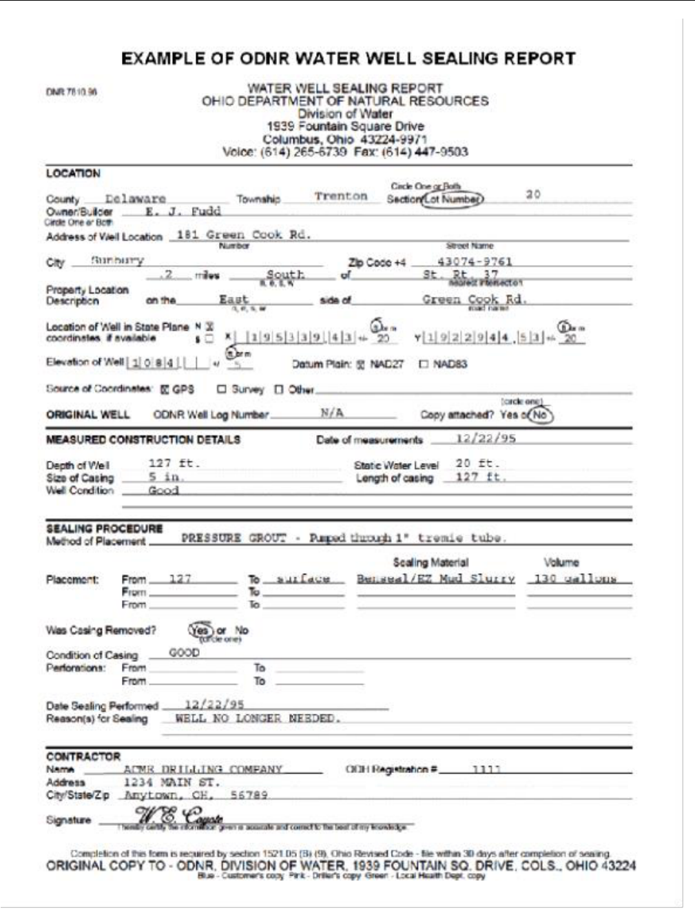
Guidelines for Design of Small Public Ground Water Systems
June 2023
Page 74 of 77

Guidelines for Design of Small Public Ground Water Systems
June 2023
Page 75 of 77
APPENDIX G - Hauled Water System – Design Requirements

Guidelines for Design of Small Public Ground Water Systems
June 2023
Page 76 of 77
Hauled Water System - Design Requirements
Public water systems using hauled water are exempt from Section 6109.02 of the Ohio Revised Code if all of the
following conditions are met:
1. Consists only of distribution and storage facilities and does not have any collection and treatment
facilities.
2. Obtains all of its water from, but is not owned or operated by, a public water system.
3. Does not sell water to any person.
4. Is not a carrier which conveys passengers in interstate commerce.
If the proposed hauled water system will qualify for the exempt status, then the District Office should be notified
accordingly. If it will not qualify as an exempt system, then detail plans must be submitted and approved prior
to construction of the hauled water system. Hauled water systems should only be considered for noncommunity
public water systems. General design criteria and the type of information to be presented on the detail plans are
as follows:
1. Name of the project
2. Owner’s name and address
3. Vicinity map showing project location
4. Name of person/firm preparing the plan
5. A site plan, drawn to scale, showing existing and/or proposed:
a) Property lines
b) Outline of buildings, including those relevant to the project which are located on adjacent
properties
c) Water system location
d) Sewerage system location
e) North arrow to show orientation
f) Underground utilities which are possible sources of contamination to a buried bulk water tank
(storm sewer, sanitary sewer, oil/gas lines, etc.)
6. Design parameters
7. Tank:
1. Tank should be sized to provide 3 to 5 days storage; however, the tank should not be less than
either 2,500 gallons or the size of the water hauler’s tank. Under special conditions or extremely
low flows, tanks smaller than 2,500 gallons can be considered. Supplemental chlorination may
be necessary if the tank will sized for more than 5 days of storage. A very large hauled water
system shall be constructed with multiple tanks that can be independently isolated and de-
watered to facilitate cleaning and maintenance.
2. Tank materials include: concrete, fiberglass, plastic and steel. Steel tanks should not be buried.
Buried fiberglass or plastic tanks must be secured to a concrete pad to address flotation
concerns. If in an area of VOC contamination, fiberglass and plastic tanks are not permitted
below grade.
3. Means to evaluate water level
4. Low level alarm
5. 24 inch diameter access manhole

Guidelines for Design of Small Public Ground Water Systems
June 2023
Page 77 of 77
6. Sanitary fill
7. Overflow
8. Vent
9. Security
10. Drain
11. Final grading provides positive drainage away from tank
8. Discharge pump/pressure tank:
1. Discharge pump capacity ≥ peak hourly demand
2. Discharge pump centerline to be below lowest water level
3. Pressure tank(s) drawdown must satisfy pump manufacturer’s minimum run time
9. Miscellaneous:
1. Sample tap(s)
2. Associated piping approved for potable water
3. Identification of water hauler (must be registered with the local health department)
4. Identification of water source(s) (must be from an approved municipal supply)

Guidelines for Design of Small Public Ground Water Systems
June 2023
Page 78 of 77
Central Office
Lazarus Government Center
50 W. Town St., Suite 700
Columbus, OH 43215
(614) 644-3020
Northwest District Office
347 N. Dunbridge Rd.
Bowling Green, OH 43402
(419) 352-8461
(800) 686-6930
Northeast District Office
2110 E. Aurora Rd.
Twinsburg, OH 44087
(330) 963-1200
(800) 686-6330
Central District Office
Lazarus Government Center
50 W. Town St., Suite 700
Columbus, OH 43215
(614) 728-3778
(800) 686-2330
Southeast District Office
2195 E. Front Street
Logan, OH 43138
(740) 385-8501
(800) 686-7330
Southwest District Office
401 E. Fifth St.
Dayton, OH 45402
(937) 285-6357
(800) 686-8930
Toll-free numbers are for citizens with questions or concerns about environmental issues.
The regulated community should use the business line for routine business.
Spills and emergencies should be reported to (800) 282-9378.
