
4
th
Year Project
Interim Report
_______________
Group 1
_______________
Design and Manufacture of Electrical and
Control Systems for an Underwater ROV
_______________
Contributors:
Benjamin Griffiths
George Osmond
Henry O’Keeffe
Joseph Orford
Supervisors:
Dr. Dan Gladwin
Mr Ken Mitchell
Word Count:

Interim Report 10/02/2020
1. Project Aims and Objectives - Review (BG)
As discussed in the initial project initialisation report, the overall objective of this project is to
design, manufacture and test an electronics and software control system for an underwater remotely
operated vehicle (ROV). The control system must be capable of controlling the various
electromechanical and sensory devices on the ROV, such as thrusters, pneumatic actuators, cameras
and sensors.
Figure 1 shows the projects current status based on the aims presented in the initialisation report.
Figure 1: Project progress.
The functional requirements and technical specification have not changed significantly since the
start of the project, hence the progress so far has been as predicted and there is confidence that most
or all of the aims will be met or exceeded.
The final specification for each task that the ROV must be able to complete has been released, so the
functionality requirement is now known for the electronics system and the control software. This
was suitably accounted for in the initial functional requirements, with the electronics design
supporting control of more actuators, sensors and cameras than was thought needed. Therefore, no
change in the design is required.
The first version of the electronics system PCBs have been designed, sent off for manufacture,
populated and tested. The faults and issues with the first version are currently being addressed with
the second version designs.
2. Project Progression
2.1. Benjamin Griffiths
The first revision of the interface PCBs, responsible for interfacing the data and power PCBs to the
external underwater connectors, and the ESC unit testing PCB, have been ordered, populated and
tested.
The power end PCB, responsible for connecting the thruster and power connections, meets the
technical requirements, hence no further revision is needed. The full power end-cap assembly,
containing the PCB, underwater connectors and mounting plate is shown in Appendix Figure x.
The data end PCB, responsible for connecting the cameras, thrusters, communication lines and
sensors, does not meet the technical requirements, due to not including USB connections for digital
1

Interim Report 10/02/2020
video feeds, and incorrect ethernet routing. This PCB design is currently being revised to meet the
requirements.
The ESC unit testing PCB, responsible for testing the ESC modules independently from the rest of the
electronics system, has been fully tested and performs all the required functionality. No further
design revision is required. The final PCB is shown in Figure 2.
Figure 2: ESC Breakout Board For ESC Testing
The software aspect of the project has had excellent progress, both with the embedded C code
running on the ROVs microcontroller, as well as the Python pilot control interface program.
The pilot control program, developed in Python and PyQt5 takes the form of a fully customisable,
easy to use yet powerful graphical user interface. The following list explains the current key features
of the program:
➔ View and switch between digital camera feeds
➔ Receive control inputs from an XBOX controller
➔ Reconfigurable key bindings for ROV controls
➔ Automatically connects to correct COM port to communicate with ROV
➔ Request and display sensors readings from the ROV at 100Hz refresh rate
➔ Toggle the ROV actuators
➔ Independently control speed of each ROV thruster
➔ Allow direction of each thruster and its position on the ROV to be specified
➔ Launch the various machine vision tasks
➔ Change controller sensitivity to perform precise movements
➔ Change ROV control orientation to drive in reverse
The program in its current state is able to control most of the required functionality to control the
ROV at the competition, and can be easily configured to adapt to future ROV designs.
The thrusters on the ROV are arranged so that each thruster is offset by 45° to the X, Y and Z axis, as
seen in Figure x. This means that each thruster has a contribution to the ROV thrust in all 3 axes. A
2

Interim Report 10/02/2020
thrust vectoring algorithm has been developed to convert the XBOX controller joystick positions into
speed values for all 8 thrusters, allowing control of the ROVs pitch, yaw and roll, as well as up/down,
right/left and forward/backward movements. This was achieved by analysing each thruster in turn,
to see whether it has a positive or negative contribution to roll or pitch etc. when the thruster is being
driven forward. This generates an array with 8 speed values for each thruster. These values are then
normalised to the highest speed value and joystick position, so that the values are in the range 1 -
999 to be sent to the ROV via serial communication.
This algorithm has been tested on a small prototype ROV in a water tank and is able to control the
ROVs movement and rotation in all 3 axes. However, the ability to precisely control the ROVs position
can only properly be tested in a large body of water, so fine tuning of the algorithm may be required
in the future.
The C code running on the ROV in the Arduino environment has also progressed, with a simple and
reliable serial interface that uses ASCII commands to control the thrusters, actuators, camera signal
switches and sensors. The commands start with ‘?’ followed by an alphabetical character (acts like an
address) that indicates which aspect of the ROV the command is trying to control, followed by the
required data. This makes serial communication with the ROV simple human readable, allowing the
ROVs basic functions to be tested via command line without needing to use the GUI program. The
commands currently implemented are shown in Appendix Ben.
2.2. Joseph Orford
This PCB is responsible for the data processing of the project. This includes the main microcontroller
and microprocessors for doing the processing of the control system, control signals and camera
processing. The board takes 48V from the main supply and regulates it to 5v, 3.3v, 2.5v, 1.8v and 1.2v
for all of the systems on board at varying power levels. The board can take USB, ethernet, CSI and
analog camera inputs which can be sent up the tether differentially or via the fibre optic connection.
The on board microprocessors allow for image processing as well as server hosting for a backup
communications system with the surface. This board is responsible for all the communications with
the surface and mini-ROV and has multiple differential transceivers.
The board is designed to have multiple redundancy elements, such that if one system was to fail,
there is another which can be switched to within seconds. This has been achieved with the
implementation of at least two methods of achieving the same sensor reading communication
method. This is because the PCB will be in hot, humid conditions which can lead to failures of the
PCB. The PCB will be conformally coated to help alleviate this issue, with limited effect as
components such as connectors cannot be conformally coated.
The first revision of the PCB was completed and tested, as shown in figure [JOE1]. There were several
errors on this PCB, most notably the interconnections between two Physical Ethernet Layers (PHYs)
were incorrect and resulted in multiple modifications for the next revision. Further potential errors
were found with the 3v3 power supply unit in that it couldn’t supply enough current for sustained
usage with all elements being used. Brownouts could occur if all features were active at the same
time. The ethernet switch and fibre optics were a success, achieving speeds over 100 Mbps. This is
significantly less than the datasheet specification, so work will be done to remove the bottlenecks.
3

Interim Report 10/02/2020
There were other issues with the usage of certain on board communications. In an oversight, it was
discovered that the cameras could not be used at the same time as they shared the same control lines,
and also the USB hub could not function at the same time as the cameras whilst the Arduino was
communicating with it. These issues require a minor rearrangement of components and changes to
the pins connected.
Joe 1 showing the first revision PCB and layout
Revision 2, shown in figure X, looks to optimise the design and add extra features. The components
have been placed and routing has begun. Power over Ethernet (PoE) has been added so that ethernet
cameras can be powered conveniently. This has resulted in the addition of ethernet magnetics to
isolate each connection. The FPGA has been removed and has been replaced with a microchip
Microprocessor Unit (MPU) which is using DDR3 memory and will be designed to run a linux
distribution. This module is for redundancy in the event of the Raspberry Pi hanging during
operation. This MPU connects to the system via the ethernet switch and via USB.
Joe 2 showing the latest PCB render and PCB layout
2.3. Henry O’Keeffe
The first revision of the Electronic Speed Controllers have been designed, the PCBs made, and the
boards populated. A program has been developed, but not yet tested that will allow motor control
with Field Oriented Control (FOC).
Figure HENRY 1 and figure 2 (ben) shows the ESC designed with LMG5200 Gallium Nitride (GaN)
MOSFET half-bridge modules. This design has a maximum current of 10 A, and can operate at very
high PWM frequencies (>100 kHz) with negligible switching loss. The GaN ESC is equipped with 4
LEDs for debugging and status.
4

Interim Report 10/02/2020
Henry 1
Figure HENRY 2 shows the ESC designed with traditional Silicon MOSFETs. This design has a higher
maximum current than the GaN device at 20 A, however they cannot achieve as high frequencies,
with switching losses becoming significant above 25 kHz. Due to additional I/O required for the more
advanced gate driver, the Si ESC features only one microcontroller debugging LED and two driver
fault/status LEDs.
Henry 2
Both ESCs function are designed to accept 48 V DC nominal, feature on-board DC/DC converters to
power the dual-core dsPIC33CH512MP505 microcontroller (µC). They both run similar programmes
on the cores, one core acting as a master responsible for the communications (RS-485 with I2C,
analogue and PWM as backups) with the slave running the FOC algorithm and PLL rotor position
estimator, controlling the inputs of the LMG5200 GaN half-bridge modules or DRV8301 gate driver
directly.
The basic functionality of the GaN PCB has been proven working, with the exception of the current
sense amplifier. Due to the extra complexity of the Si MOSFET driver (the requirement for an SPI
setup routine), the Si ESC will require extra programme complexity, so will be tested after the Si ESC
programme development is underway.
5

Interim Report 10/02/2020
In addition to the GaN and Si ESCs, a third is being developed to act as a backup. This will house a
commercial ESC, adapting the interface from RS-485 on the signal input side to a single pin servo
Pulse-Position Modulation with an ATmega4809. This PCB also provides a 48 V to 12 V DC/DC
converter, as the commercial ESCs are designed to run at a lower voltage than the 48 V available.
All three ESCs will be produced in quantity after redesign if necessary, and their performance
evaluated and compared with each other, however the design of the third ESC is currently stalled,
awaiting the footprint of the commercial ESC to be designed which depends on the arrival of the
commercial ESCs, expected the week of the 10th of February.
2.4. George Osmond
As discussed in the initial project report, the power board is needed to provide the power for all the
external components of the ROV: any components that are outside of the control enclosure such as
the thrusters, solenoid valves, cameras and any required actuators in order to complete the tasks set
out by the MATE ROV competition specification. The power management must be done on a seperate
board to the control board due to high-impedance signals on the control board that can easily be
interfered with by high current traces running in close proximity. A separate PCB for high currents
prevents this. This also allows for the PCBs to fit easily within the enclosure as they can be stacked
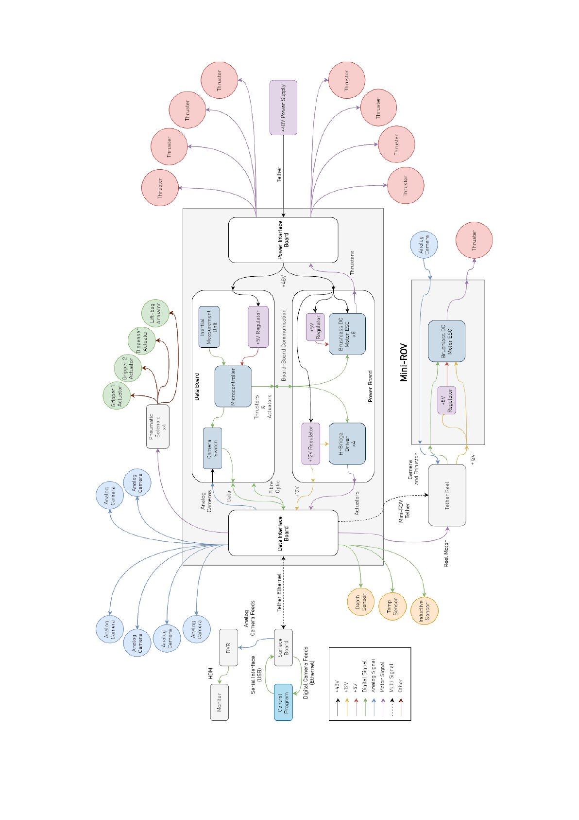
and interfaced by the end cap boards. Appendix A shows the overall system flowchart for all the
components required on the power board.
Figure George 1: Render of Revision 1 Power PCB
The first revision (shown in George 1) of the power board utilised 2oz thick copper to allow for high
current carrying traces that could be made thinner and easier to route. This made soldering small
components difficult as the board required a lot of power to melt the solder due to the copper’s high
thermal capacity. The initial decision behind using 2oz copper was to ensure that each trace for each
thruster phase was capable of carrying enough current for all thrusters to be running on full load.
This meant the traces must be able to carry roughly 7 A for a sustained period of time, in order for
this to be possible the traces needed to be a minimum of 1.6mm wide. This made routing the PCB
difficult due to components on the PCB creating narrow paths for the traces to run through.
6
Interim Report 10/02/2020
For the 12 V regulator a Texas Instruments L5146-Q1 was used, which is a synchronous buck
controller rated to up to 100 V. This was used to provide 12 V at 10 A to the cameras and h-bridges
which are used to control any external motors or solenoid valves that will be used. This regulator
came in a 20-pin VQFN package that proved difficult to solder due to the 2oz copper traces used as
the package had no visible legs to solder to, only small pads on the underside of the chip with
wettable flanks.
The second regulator used on the power board is the 5 V at 5 A regulator which is used to feed the
ESCs with 5 V for on board logic. This is also connected to the data board 5 V rail through a jumper
and then the board to board connector. The 5 V regulator used was the microchip MIC2128 which
comes in a 16-pin QFN package, which, similarly to the LM5146-Q1, uses pads on the underside of
the chip rather than legs which proved difficult to solder due to the 2oz copper layer.
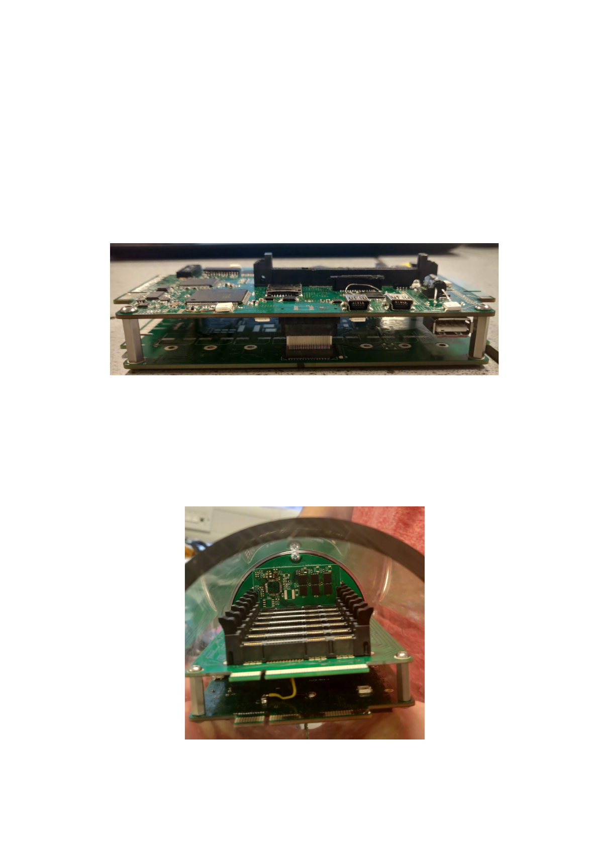
George 2: Showing the board-to-board connector between the data and power board
The connectors which are mounted to the PCB to allow for interfacing between the ESCs and the data
board were tested. Figure George 2 shows the data board and the power board connected together as
they will be inside the capsule with the board-to-board connector allowing for signals to be sent
throughout the entire control system. Figure George 3 shows the ESC connectors which allow for
easy removal and replacement of ESC’s in the case of a fault.
George 3: Showing the Modular ESC Connectors
7

Interim Report 10/02/2020
Revision 2 of the power board design will use more suitable packages that are easier to solder and
easier to fault find as the pins and pads will be visible and easier to probe on to for unit tests and a
full system test. The 12 V regulator will use Texas Instruments LM5088-Q1 which comes in a HTSSOP
package and also requires fewer components to achieve the desired output which will also make
routing easier. As well as this the 5 V regulator that will be used is the LM5085 which comes in a
VSSOP package and will allow for much easier soldering and testing. Along with the better selection
of components the PCB will be redesigned using 1oz copper traces and a 4 layer board which will
allow for a ground and 48 V plane to be put in place which will increase the ease of routing. The 1oz
copper will make for much easier soldering due to the lower thermal mass of the copper traces. One
downside to 1oz copper traces is the fact that the traces would need to be roughly 4mm wide in order
to carry the same amount of current as the previous 2oz traces. The easiest way around this is to
remove the solder mask from the motor traces and solder directly onto the traces to increase the
thickness of the trace. This is an industry standard method of creating high current traces on a low
weight copper board. These changes should allow for the board to be fully working, ready for a full
system test aligning with the timescale set out in the Gantt chart.
3. Review of Project Schedule (GO)
The Gantt chart has proven to be an accurate representation of the current progress of the project
and all aspects are on track and meeting any deadlines set. In order to ensure that project progress
stays within the current deadlines and is set to meet the final deadline for the competition, a close
eye will be kept on timings and the team will ensure that all efforts are made to keep the project on
track. The initial Gantt chart is shown in Appendix X and shows that the current state of project is
testing and redesign, which has been explained in the previous sections of this report.
As the project approaches completion it is of high importance that the team keeps within the
proposed timeline to ensure that the final deadline is met. The initial plan allowed for some overflow
to occur and allow for extra time if needed for final tweaks and tests to ensure that the project is
ready for the competition.
4. Review of Risk Register (HO)
Out of the applicable risks at this stage of the project, only No. 4, “delays due to late / slow ordering
of components” presented an issue. (See Appendix C for the Risk Register). The Commercial ESCs,
critical for the backup system, still have not yet arrived, despite ordering them 3 months ago though
our budget with the Multidisciplinary Engineering Education department. Several attempts to speed
up the process have been carried out, and apparently the ESCs have been ordered, however they have
not arrived. During the writing of the Risk Register, the impact of poor communications in the
near-side supply chain was not considered in Risk No. 4. Instead, the focus was on delays at the
supplier level.
Unfortunately, there is little that can be done within the scope of the project, so the only alteration
the the risk factors is to increase the likelihood after mitigation to 2, and to acknowledge and accept
the high risk factor of 10.
8

Interim Report 10/02/2020
5. Appendix
Command
Initialiser
Command
Function
Data
Description
?I
-
-
Requests the identity of the ROV,
responds with ‘AVALONROV’.
?R
T
aaabbbcccdddeeefffggghhh
Sets the speed of each thruster. ‘Aaa’
represents the speed of thruster 1 from
‘001’ -’ 999’.
X
-
Arms the thruster electronics speeds
controllers (ESC’s).
A
abcdefgh
Sets the state of each actuator. ‘A’
represents the state of actuator 1, either
‘0’ or ‘1’.
C
aabbccdd
Sets the analog camera switches to
display the 4 desired camera feeds. ‘Aa’
represents the address of camera 1, from
‘01’ - ‘99’.
?M
X
a
Activate the mini-ROV, arm the thruster
ESC and turn the headlights on. Where ‘1’
is ON and ‘0’ is OFF.
T
aaa
Sets the speed of the mini-ROV thruster.
‘Aaa’ represents the speed from ‘001’ -
‘999’.
For example, if the pilot wanted to set thruster 1 to maximum speed, the command would be,
“?RT999500500500500500500500”, or to toggle actuator 3, the command would be “?RA0010”.
Appendix A: ROV ASCII commands.
Appendix B: System Flow Chart For Power Board Operation
9

Interim Report 10/02/2020
Appendix C: Gantt Chart for Project Planning and Timescale Management
10

Interim Report 10/02/2020
No.
Risk to Project
Severity
Likelihood
Risk
Rating
Mitigation
Updated
Severity
Updated
Likelihood
Final
Risk
1
Scope Creep
increasing
workload,
causing delays in
task completion.
4
4
16
Properly define a
fixed specification at
the initialisation of
the project (in this
document) and refer
to it frequently.
4
2
8
2
Poor
understanding
of project
requirements.
5
3
15
Spend additional time
ensuring the project
requirements, then
write the specification
to ensure full
coverage.
5
1
5
3
Pressures from
other projects
and exams.
4
4
16
Ensure other events
(exams, etc.) are
accounted for in the
project planning
phase.
4
1
4
4
Delays due to
late or slow
ordering of
components /
PCBs.
5
3
15
Use the schedule to
plan ahead
component ordering
once requirements
have been identified.
After final checks,
order PCBs at the next
available opportunity.
5
1
5
5
One or more
tasks are not
known at the
planning stage.
4
3
12
Ensure full coverage
by cross-checking
specification against
aims.
4
1
4
6
Communication
between team
members breaks
down, causing
task duplication
or loss.
4
4
16
Conduct regular
meetings in person
and avoid the use of
social media to
conduct important
conversations.
4
1
4
7
Time pressure
due to nearing
deliverable
deadlines causes
non-functioning
/ poor quality
work.
3
4
12
Adhere to the project
plan, completing
work earlier if
possible to ensure an
acceptable workload
immediately before
deadlines.
3
1
3
8
Knock-on delays
build such that
the lost time is
unrecoverable.
5
4
20
Plan extra time into
the schedule to act as
contingency for any
unexpected delays.
5
1
5
11

Interim Report 10/02/2020
9
MATE
Specification, on
release, reveals
incorrect
assumptions
about tasks,
leading to a lack
of requirement
planning.
5
3
15
Design for additional
features in the
electronic systems to
cover all possible
specification
variations; ensure
system is expandable.
5
1
5
10
Testing does not
cover the
boundary
conditions of the
electrical
system, and
discrepancies
with the
specification are
not noticed.
3
4
12
Use unit testing,
where tests
(especially for
software) are built
before the module
concerned. This
ensures that,
provided the test is
accurate, the product
meets the
specification.
3
2
6
11
Data loss due to
individual poor
backup regime
causes project
delays.
5
4
20
Use online services
such as google drive
to synchronise
personal data.
5
1
5
Appendix D: Risk Register Showing Major Risks and Attempted Risk Mitigation
Likelihood
1
2
3
4
5
Risk
Rating
Description
Im
pac
t
1
1
2
3
4
5
1-2
Low priority risk - risks we are willing to take and won’t
affect project progress.
2
2
4
6
8
10
3-6
Moderate risk-risk will need monitoring but not a large
threat to project completion.
3
3
6
9
12
15
8-12
High risk - risk will need monitoring and action will need to
be taken to prevent risk from affecting project progress.
4
4
8
12
16
20
15-25
Critical risk - risk is detrimental to project progress and
processes must be put in place to prevent it.
5
5
10
15
20
25
Appendix F: Description of Risk Rating
Appendix E: Risk Rating Based on
Likelihood & Impact of Risk
12
Interim Report 10/02/2020
Appendix G: Overall System Flowchart For ROV Control System
13
