
OUTDOOR FIRE TABLE USER MANUAL
OUTDOOR FIRE TABLES: OLT24GMAPT, OLT24BMAPT, OLT36GMAPT,
OLT36BMAPT, OLT48GMAPT, OLT48BMAPT
OUTDOOR BURNERS: OB24MAPT, OB36MAPT, OB48MAPT ARE
CERTIFIED FOR USA & CANADA- ANSI Z21.97-2017 • CSA 2.41-2017
OUTDOOR DECORATIVE GAS APPLIANCES
NOTE: LP MANUAL (MAPT) VALVE SYSTEMS ARE SHIPPED WITH AN
ACCOMPANYING ORIFICE FOR NG CONVERSION.
For detailed instructions and information refer to the OUTDOOR
LINEAR FIRE PIT MANUAL at https://barbarajeancollection.com/.
⚠ DANGER
FIRE OR EXPLOSION HAZARD
If you smell gas:
• Shut off gas to the appliance.
• Extinguish any open flame.
• If odor continues, leave the
area immediately.
• After leaving the area, call your
gas supplier or fire
department.
Failure to follow these
instructions could result in fire
or explosion, which could
cause property damage,
personal injury, or death.
⚠ WARNING
Do not store or use gasoline or
other flammable vapors and
liquids in the vicinity of this or
any other appliance.
An LP-cylinder not connected
for use shall not be stored in
the vicinity of this or any other
appliance.
⚠ WARNING
For Outdoor Use Only.
Installation and service must
be performed by a qualified
installer, service agency, or the
gas supplier.
⚠ WARNING
If the information in this
manual is not followed exactly,
a fire or explosion may result
causing property damage,
personal injury, or loss of life.
⚠ DANGER
CARBON MONOXIDE HAZARD
This appliance can produce carbon
monoxide which has no odor.
Using it in an enclosed space can
kill you.
Never use this appliance in an
enclosed space such as a camper,
tent, car or home.
Kingsman Fireplaces 2340 Logan Ave., Winnipeg, Mb Canada Ph: 204-632-1962 Printed in Canada P/N 24OLT-MAN17 June 23, 2021
INSTALLER: Leave this manual with the appliance.
CONSUMER: Retain this manual for future reference.
This appliance is designed as an “attended appliance”. Adults
must be present when the unit is operating. DO NOT leave this
unit burning when unattended. If this product is left burning
unattended it may cause damage or serious injury.
*QUICK SETUP
GUIDE LOCATED ON
PAGES 3-4

- Table of Contents -
Table of Contents…………………………………………………………………………………………..
2
Quick Setup Guide…………………………………………………………………………………………
3-4
20lb Cylinder Installation…………………………………………………………………………………..
5
Pre-installation Questions and Answers…………………………………………………………………
6
Important Information About Outdoor Fireplaces……………………………………………………….
6
Warnings…………………………………………………………………………………………………….
7
Gas Line Installation……………………………………………………………………………………….
7
Locating Your Appliance…………………………………………………………………………………..
8
Dimensions………………………………………………………………………………………………….
9
Glass Media for Outdoor Burners………………………………………………………………………...
10
Optional Media Accessories………………………………………………………………………………
10-11
Wind Guards for Fire Tables……………………………………………………………………………...
12
Burner Lids- Optional………………………………………………………………………………………
13
Lighting Instructions………………………………………………………………………………………..
14
Burner System Maintenance……………………………………………………………………………...
15
General Maintenance Instructions………………………………………………………………………
16
Gas Conversion Instructions……………………………………………………………………………...
17
Troubleshooting the Gas Control System……………………………………………………………….
18
Plumbing Parts……………………………………………………………………………………………..
19
Parts List…………………………………………………………………………………………………….
20-21
Gas Specifications…………………………………………………………………………………………
21
Limited Warranty…………………………………………………………………………………………...
22
2

Barbara Jean Fire Tables – Quick Setup Guide
Your Barbara Jean Fire Table can be set up in 6 Easy Steps:
Step 1: Install Plastic Feet.
Step 2: Set Fire Table in place.
Step 3: Place Media over Burner.
Step 4: Assemble Wind Guard.
Step 5: Install LP Cylinder.
Step 6: Install [1] AAA Battery
(not supplied) into Igniter.
Step 1: Install
Foot Pads.
Remove the plugs
from the threaded
hole at each
corner of the
cabinet. Install the
supplied Plastic
Feet using a
Robertson
screwdriver.
Step 2: Set Fire Table in place.
The Fire Table Top Edge must maintain
the following minimum clearances from
combustible materials:
-End of Table Top – 4”
-Side of Table Top– 14”
-Table Top to Ceiling – 50”
WARNING - FOR
OUTDOOR USE ONLY
DANGER – CARBON
MONOXIDE HAZARD
Screened Porch - Minimum porch area
is 96sq. feet with two sides fully open. A
minimum of two (2) walls can be
screened, but must be open to outside
ventilation, with a minimum screen area
of 64 sq. feet, and a minimum side wall
height of 78” inches.
For detailed
information refer to
the product manual.
14”
4”
50”
WARNING -RISK OF FIRE-
All minimum clearances must be adhered to.
3

Step 3: Install Burner Tray Filler Strips &
Place Media over Burner.
Filler Strips must be installed before media is
placed onto burner.
Spread Bronze Glass evenly in burner tray.
Pilot Shield must not be covered, as a delayed
ignition can occur.
Refer to Manual for detailed instructions.
Step 4: Assemble the Wind Guard.
Step 5: Install Propane Cylinder.
Step 6: Install [1] AAA Battery (not supplied) into
Igniter.
Pilot Shield must not be covered
Follow the Lighting
Instructions in the
manual or on the
back of the Label
Plate to light the
appliance.
Tank Brace
4

20lb Cylinder Installation - Fire Table -
⚠ Only a 20LB LP Cylinder may be used inside the Fire Table Enclosure.
NOTE: Cylinders acceptable for use inside this appliance must be compatible with the retention means shown here.
• The LP gas supply cylinder used with LP models must
be constructed and marked in accordance with the
specifications for LP-gas cylinders of the U.S.
Department of Transportation (DOT) Specifications for
LP-Gas Cylinders, or the Standard for Cylinders,
Spheres and Tubes for Transportation of Dangerous
Goods and Commission, CAN/CSA-B339, as applicable.
• The LP gas supply cylinder used with LP models must
be provided with a listed overfilling prevention device.
• The pressure regulator and hose assembly supplied with
LP models (PN# 27FP-900FF) must be used.
Replacement pressure regulators and hose assemblies
must be those specified in this manual.
• Always check for gas leaks with a soap and water
solution. DO NOT USE OPEN FLAME FOR LEAK
TESTING.
• When an LP model is not in use, the LP-gas must be
turned off at the supply cylinder.
Bottom of LP
Cylinder Drops
into Round Hole
Replace Tank Brace.
Slide over Protective
Collar of 20lb cylinder
and tighten.
Installation of 20lb Cylinder
into Fire Tables:
• Remove Top Clamp.
• Connect 20lb cylinder to
regulator.
• Place 20lb cylinder into
Fire Table as shown.
• Secure 20lb cylinder with
Tank Brace as shown.
Tank Brace
5

Pre-installation Questions and Answers
About curing of the paint
Your stove or fireplace has been painted with the highest quality silicone stove
paint. This paint dries quickly in 15-20 minutes when first applied at the factory.
However, due to the high temperature silicone components, the paint will cure
when heat is applied to the appliance as it is first used. The following
information applies to the curing process to get the paint fully hard and durable.
Fire the appliance four successive times for 10 minutes each firing and a 5
minute cool down between each. Be aware during log and firebox paint curing
that a white deposit may be developing on the inside of the glass doors. It is
important to remove this white deposit from the glass doors using a fireplace
glass cleaner.
• Babies, small children, pregnant women and pets should leave the
area during the cure phase.
• Ventilate well, open doors and windows.
• Do not touch during curing.
Why does my fireplace or stove give off odor?
It is normal for your fireplace to give off some odor at first. This is due to the curing of the paint, adhesives, silicones and any
undetected oil from the manufacturing process as well as the finishing materials used with the installations (e.g. marble, tile and the
adhesives used to adhere this product to the walls can react with heat and cause odors).
It is recommended that you burn your gas fireplace or stove for a minimum of four hours at a time with the fan off (if a fan is present)
after the curing of the paint has been completed. These odors can last upward to 40 hours of burn time; keep burning at a minimum
of four hours per use until odors dissipate.
Noise coming from the fireplace?
Noise is caused by the expansion and contraction of metal as the appliance heats up and cools down. This is normal and is similar
to the sounds produced by a furnace or heating duct. This noise does not affect the operation or longevity of your fireplace.
Note to the Installer:
Be sure appliance is working properly and its operation (including remote control operation, if included) is fully explained to and
understood by the customer.
Important Information About Outdoor Fireplaces
Before you build in this appliance:
• Do not insulate around the appliance. Heat buildup
could lead to component failure.
• Pay attention to all clearances to combustibles and
specifications stated in this manual.
• Drainage- If this appliance is installed in a location
where it will be exposed to water and moisture,
drainage is an important consideration.
• Inadequate drainage will cause rust, which is not
covered by the warranty.
Information about outdoor fireplaces
• Outdoor fire burning appliances may not function
properly at all times regardless of the circumstances.
• Wind can greatly affect flame performance. If used in windy conditions a wind guard is recommended.
• Outdoor units require adequate ventilation in order to burn properly.
• Restricted access to air is not only dangerous for persons near the appliance, but the appliance also will not function
correctly.
• This appliance consumes air, burns fuel, and emits heat and exhaust gases.
• Only approved media and accessories listed in this manual should be used with this appliance.
• This appliance is not intended for use in temperatures below freezing.
• The pilot burner (if equipped) should be OFF, and covered to protect it from the elements when not in use.
-Operating Instructions-
1. Be sure to read and understand all the
instructions in this manual before
operation of appliance.
2. Ensure all wiring is correct and properly
enclosed to prevent possible shock.
3. Check for gas leaks.
4. If brick or porcelain liners are used,
ensure they are installed.
5. Verify that the pilot can be seen when
lighting the appliance. If not, the log or
rock placement is incorrect.
6. If the unit is turned off, you must wait a
minimum of 60 seconds before re-
lighting it.
6

WARNING
FOR SAFE INSTALLATION AND OPERATION OF YOUR GAS FIREPLACE PLEASE NOTE THE FOLLOWING:
1. when an appliance is for connection to a fixed piping system, the installation must conform with local codes or, in the
absence of local codes, with the National Fuel Gas Code, ANSI Z223.1 • NFPA 54; National Fuel Gas Code; Natural Gas
and Propane Installation Code, CSA B149.1; or Propane Storage and Handling Code, CSA B149.2, as applicable.
2. This appliance, when installed, must be electrically grounded in accordance with local codes or, in the absence of local
codes, with the National Electrical Code, ANSI/NFPA 70; or the Canadian Electrical Code, CSA C22.1, if applicable.
3. THIS UNIT IS NOT FOR USE WITH SOLID FUEL.
4. Always keep the appliance clear and free from combustible materials, gasoline, and other flammable vapors and liquids.
5. Inspect the fuel supply connection (including the hose for LP models) before each use of the appliance. See Lighting
Instructions for removal of Access Panel.
6. If it is evident there is excessive abrasion or wear, or the hose is damaged, it must be replaced prior to the appliance being
put into operation. Locate the hose out of pathways where people may trip over it or in areas where the hose may be
subject to accidental damage
7. Locate the hose out of pathways where people may trip over it or in areas where the hose may be subject to accidental
damage.
8. Children and adults should be alerted to the hazards of the high surface temperatures of this appliance and should stay
away to avoid burns or ignition of clothing.
9. Young children should be carefully supervised when they are in the area of the appliance.
10. Clothing or other flammable material should not be placed on or near the appliance. This appliance should not be used as a
drying rack for clothing.
11. Any safety screen or guard removed for servicing an appliance must be replaced prior to operating the appliance.
12. Installation and repair should be done by a qualified service person. The appliance should be inspected before use and at
least annually by a professional service person. More frequent cleaning may be required due to excessive lint from
carpeting, et cetera. It is imperative that control compartments, burners and circulating air passageways of the appliance be
kept clean.
13. Do not use this appliance if any part has been under water. Immediately call a qualified service technician to inspect the
unit and to replace any part of the control system and any gas control which has been underwater.
- Gas Line Installation -
This gas appliance should be installed by a qualified installer in
accordance with local building codes and with current CAN/CGA -
B149.1 or .2 installation codes for Gas Burning appliances and
equipment in Canada and the National Fuel Gas Code ANSI Z223 in
the U.S.A.
1. The gas pipeline can be brought in through either the left side or the
bottom of the appliance. A knockout is provided at either location to
allow for the gas pipe installation and testing of any gas connection.
2. The gas control inlet is 3/8” NPT. Typical installation layout for rigid
pipe is shown at right.
3. When using copper or flex connector, use only approved fittings.
Always provide a union so that gas line can be easily disconnected
for burner or fan servicing. See gas specification for pressure details
and ratings.
4. When a vertical section of gas pipe is required for the installation, a condensation trap is needed. See CAN/CGA-B149.1 or .2
for code details.
5. For natural gas, a minimum of 3/8” iron pipe with gas minimum pressure of 4.5” w.c. must be used for supply from the gas meter.
Consult with the local gas utility if any questions arise concerning pipe sizes.
6. Ports are accessible for test gauge connection both on the inlet and outlet of the gas valve.
7. Turn the gas supply ON and check for leaks. DO NOT USE OPEN FLAME FOR THIS PURPOSE. Use an approved leak testing
solution.
8. The appliance and its individual shutoff valve must be disconnected from the gas supply piping system during any pressure
testing of that system at test pressures in excess of 1/2psig [3.5 KPa].
9. The appliance must be isolated from the gas supply piping system by closing its individual shutoff valve during any pressure
testing of the gas supply piping system at test pressures equal to or less than 1/2psig [3.5 KPa].
Note: The gas line connection may be made of 1/2” rigid pipe, 1/2” copper pipe or an approved flex connector. Since some
municipalities have additional local codes, it is always best to consult your local authorities and the current CAN/CGA - B149.1
or .2 installation code in Canada or the National Fuel Gas code ANSI Z223.1 in the U.S.A.
IMPORTANT: Always check for gas leaks with a soap and water solution. DO NOT USE OPEN FLAME FOR LEAK TESTING.
7

Locating Your Appliance
Note: Ventilation and air flow comes from openings in the walls and ceiling. Open floor space around the appliance
must not be considered ventilation and air flow space.
This unit requires combustion air and will produce exhaust gases. Install in an open-air situation with natural
ventilation and without stagnant areas.
Avoid installing in tight spaces and corners.
Be aware of combustibles (i.e. furniture) near appliance. Clearance is 12” when using a wind guard.
By definition, an outdoor space is not enclosed. Any area in which these appliances are used shall comply with
the structures shown below.
Locating Your Appliance – Outdoor Spaces
This appliance may be installed within the following structures:
1.
Walls on all sides (Minimum
area of 96 square feet), but
with no overhead cover and
at least one permanent
opening (doorway) at
ground level.
2.
Within a partial enclosure
that includes an overhead
cover and no more than
two side walls.
3.
These side walls may be
parallel, as in a
breezeway, or at right
angles to each other.
4.
Within a partial enclosure
that includes an overhead
cover and three side walls,
as long as 30 percent or
more of the horizontal
periphery of the enclosure is
permanently open.
All models can be installed safely in a screened porch area within the following guidelines:
Minimum porch area is 96sq. feet with two sides fully open.
A minimum of two (2) walls can be screened, but must be open to outside ventilation, with a minimum screen area of 64
sq. feet, and a minimum side wall height of 78” inches.
Locating Your Appliance –Minimum Clearances to Combustibles-
A Wind Guard is Required for Outdoor Fire Tables.
The Fire Table Top Edge must maintain the following
minimum clearances from combustible materials:
End of Table Top – 4”
Side of Table Top – 14”
Table Top to Ceiling – 50”
WARNING -RISK OF FIRE-
All minimum clearances must be adhered to.
8

Fire Tables –Dimensions
OLT24GMAPT
OLT24BMAPT
SUPPLIED BURNER:
OB24MAPT (c/w #32 Orifice for NG)
OLT36GMAPT
OLT36BMAPT
SUPPLIED BURNER:
OB36MAPT (c/w #15 Orifice for NG)
OLT48GMAPT
OLT48BMAPT
SUPPLIED BURNER:
OB48MAPT (c/w #15 Orifice for NG)
9

Glass Media for Outdoor Burners
Choose Glass Media ‐ 5 lbs. per Foot of Burner (i.e.: 24" burner = 10lbs)
Product
Number
Description
Spread glass evenly in burner tray.
Pilot Shield must not be covered, as a delayed ignition
can occur (See photo below).
MQG5ZG
Glass Media ‐ ZIRCON Glacier Ice ‐ 5 lbs.
NOTE: For OB36 use 4 bags (20 lbs.)
For OB48 use 5 bags (25 lbs.)
For OB72 use 8 bags (40 lbs.)
For OB96 use 10 bags (50 lbs.)
MQG5A
Glass Media ‐ 1/2" Cobalt Blue ‐ 5 lbs.
MQG5B
Glass Media ‐ 1/2" Black ‐ 5 lbs.
MQG5C
Glass Media ‐ 1/2" Bronze ‐ 5 lbs.
MQG5W
Glass Media ‐ 1/2" White ‐ 5lbs.
Use of any other glass can alter the performance of the unit
and is not covered under warranty.
Discoloration of glass media may occur if placed on the
burner, this is not covered under warranty.
Optional Media Accessories
MQRBD3 – Driftwood Log Set – 5 piece
Place Logs Randomly as shown. Do not cover Pilot.
Pilot
Area
Must Not
Be
Covered.
Maximum height of glass
media is 1” above burner tray.
SIDE VIEW
10
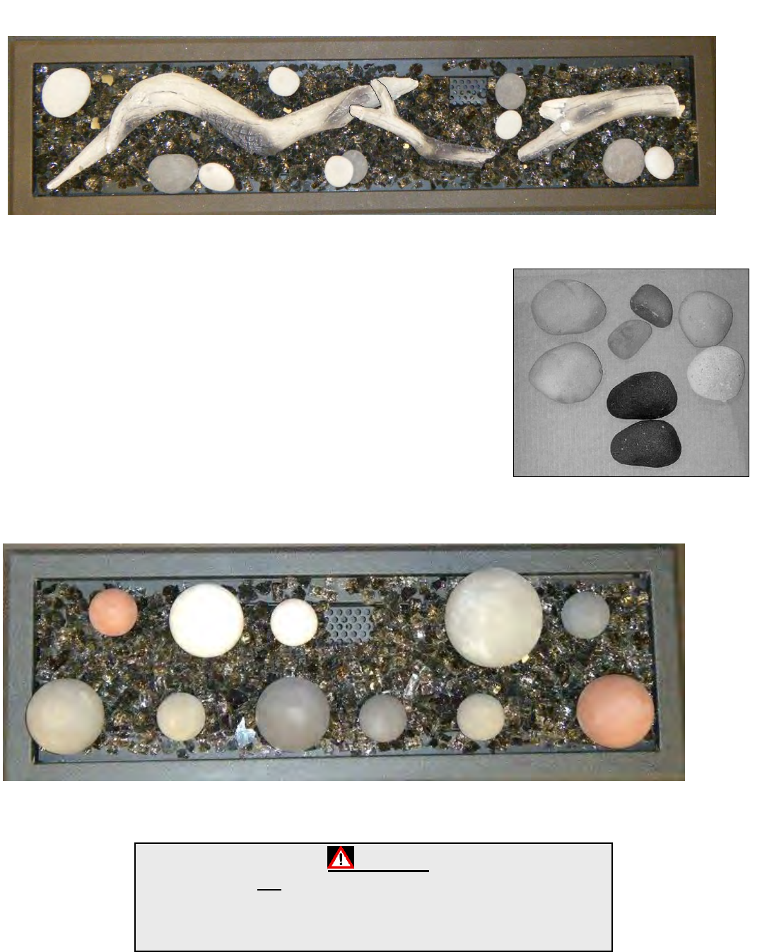
MQRBD4 – Driftwood Log Set – 3 piece
Place Logs Randomly as shown. Do not cover Pilot.
MQROCK2 – Rock Set, Contemporary Collection – Natural
MQROCK3 – Rock Set, Contemporary Collection – Multi-
Colored
MQSTONE – Decorative Stones – 80 Piece Set
MQSTONE10 – Decorative Stones – 10 Piece Set
Place Rocks and Stones randomly. Do not cover Pilot.
Not all Rocks or Stones will be used on all models.
RBCB1 – Canonballs – Assorted Size and colors- 14 pieces
Place Canonballs randomly. Do not cover Pilot. Not all Canonballs will be used on all models.
NOTE
Pilot Area Must Not Be Covered, as delayed ignition can occur.
Be Careful Not To Cover Any Part Of The Burner Tube As
Cannonballs may become discolored or sooting may occur.
11

Wind Guards
Fire Tables
A Wind Guard is Required for Outdoor Fire Tables.
Parts List: [4] Bottom Feet, [8] Corner Brackets c/w neoprene tipped screws, [2] Glass End Panels, [2] Glass Side Panels
Wind Guards: O24WG – 24” Fire Table O36WG – 36” Fire Table O48WG – 48”Fire Table
NOTE: Painted finishes damaged or discolored by heat are not covered under warranty.
Corner Bracket
c/w Neoprene
Screws
Bottom Foot
Glass Side
Panel
Glass End
Panel
WARNING: Failure to position the parts in accordance with these
diagrams or failure to use only parts specifically approved with this
appliance may result in property damage or personal injury.
12

Burner Lids for OB Burners - Optional
24LT-LID – OB24 Burners 36LT-LID – OB36 Burners 48LT-LID – OB48 Burners
Parts List:
[1] Burner Lid
- WARNING -
PILOT KNOB MUST BE TURNED TO THE “OFF” POSITION BEFORE INSTALLING BURNER LID.
SERIOUS DAMAGE CAN BE CAUSED TO THE APPLIANCE AND PROPERTY IF PILOT IS LEFT ON AND THE MAIN BURNER IS
TURNED ON WHEN BURNER LID IS INSTALLED.
ANY DAMAGE CAUSEED AS A RESULT OF THE PILOT OR MAIN BURNER BEING LEFT ON WHEN A BURNER LID IS INSTALLED
WILL NOT BE COVERED UNDER WARRANTY.
13

Safety Information and Manual Lighting Instructions
FOR YOUR SAFETY READ BEFORE LIGHTING
⚠WARNING: If you do not follow these instructions exactly, a fire or explosion may result causing property damage,
personal injury or loss of life.
A. This appliance must be lit by hand. When lighting,
follow these instructions exactly.
B. Before LIGHTING, smell all around the appliance
area for gas. Be sure to smell next to the floor,
because some gas is heavier than air and will settle
on the floor.
C. Use only your hand to turn the gas control knob or
valve. Never use tools. If the valve will not turn by
hand, don’t try to repair it, call a qualified service
technician. Force or attempted repair may result in a
fire or explosion.
D. Do not use this appliance if any part has been
underwater. Immediately call a qualified
service
technician to inspect the appliance, and to replace
any
part which has been underwater.
WHAT TO DO IF YOU SMELL GAS
• Do not try to light any appliance.
• Do not touch any electric switch; do not use any phone
in your building.
• Immediately call your gas supplier from a neighbor’s
phone. Follow the gas supplier’s instructions.
• If you cannot reach your gas supplier, call the fire
department.
Manual Valve with Push Button Ignition
1. STOP! Read the safety information above.
2. Remove the top cover.
3. Find the manual gas control valve and push
button igniter.
4. Turn ON gas supply.
5. Push and hold the button on the igniter and
ensure sparking is occurring at the probes inside
the burner tray.
6. Push in and turn the valve knob ON .
7. Gas should ignite within 10 seconds or less. If
the burner does not light turn the gas to off.
8. Wait at least five (5) minutes to clear out any
gas. Then smell for gas, including near the floor.
If you smell gas, STOP!
9. If you don’t smell gas, repeat step 4.
To Turn Off Gas Appliance
1. Turn the on/off valve to the off position at the
unit for natural gas unit. For LP unit, turn the
on/off valve to the off position at the unit and
then turn the valve on the LP tank to the off
position clockwise.
2.
Replace the top cover.
14

Burner System Maintenance
It is recommended to annually inspect and clean the Burner System to prevent malfunction and / or sooting. This operation
should be performed by your dealer or a qualified technician.
-CAUTION-
Before servicing the burner system ensure that the gas supply is turned OFF and disconnect all electrical
connections to the appliance. Allow the appliance to cool to room temperature. Note that the pilot assembly
may be hot in an intermittent or standing-pilot system—even if the main burner was never on. Exercise
caution when working within the area.
-ALL WORK SHOULD BE PERFORMED BY A QUALIFIED AND CERTIFIED TECHNICIAN-
This appliance is not intended for use in temperatures below freezing.
Monthly Flame Inspection
It is recommended to turn on the unit at least once a month and inspect the flame pattern to ensure there are no problems with
the burner tube (Flame should appear similar to the above picture).
The igniter should also be inspected monthly to ensure proper operation.
Pilot Area Must Not
Be Covered.
*Pilot Shield should be
visually inspected monthly
for signs of deterioration
due to flame exposure.
Replace if necessary.
Igniter Spark
15

OB24 / OB36 / OB48 General Maintenance Instructions
The appliance should be inspected before initial use and inspected and cleaned at least annually by a qualified field service person.
Tampering is DANGEROUS and voids all warranties. Any component that is found to be faulty, must be replaced with an approved
component.
If the burner is damaged it must be replaced with an approved burner. Refer to parts list at the back of this manual.
To obtain proper operation, it is imperative that the burner flame characteristics are steady, not lifting or floating. Check the burner
flame patterns with Burner System Maintenance Section.
Periodically remove media and examine the burner. If dirty, clean with a soft brush. Also examine the area around the burner air
shutter. Any dirt or lint in this area should be removed. This will ensure long life and trouble free operation. Replace media (rocks, logs,
glass, etc.) as shown in manual. When the appliance is put back in service, check the burner flame patterns with Burner System
Maintenance Section.
Periodically check the hose connecting the LP-gas cylinder to ensure it is not damaged in any way.
FOR SAFE INSTALLATION AND OPERATION NOTE THE FOLLOWING:
The Burner/Log Assembly has been engineered and permanently adjusted for proper flame control.
Label all wires prior to disconnection when servicing controls. Wiring errors can cause improper and dangerous operation. Verify proper
operation after servicing.
Cylinders must be stored outdoors in a well ventilated area out of the reach of children. Disconnected cylinders must have threaded
valve plugs tightly installed and must not be stored in a building, garage or any other enclosed area.
Storage of this appliance indoors is permissible only if it has been disconnected from its fuel supply (natural gas line or LP gas
cylinder).
The LP gas cylinder supply system must be arranged for vapor withdraws.
The LP gas cylinder used must include a collar to protect the cylinder valve.
When an LP model is not in use, the LP gas must be turned off at the supply cylinder.
The appliance and its individual shut off valve must be disconnected from the gas supply piping system during any pressure testing of
the system at test pressures in excess of ½ psi (3.5 kPa).
The appliance must be isolated from the gas supply piping system by closing its individual manual shutoff valve during any pressure
testing of the gas supply piping system at test pressures equal to or less than ½ psi (3.5 kPa).
CLEANING
It is recommended to annually inspect and clean the unit to prevent malfunction and / or sooting. This operation should be performed by
your dealer or a qualified technician.
Carefully remove media (log set, Rocks, Glass, etc.). Gloves are recommended.
Warning: Turn off Unit and allow to cool before cleaning. Only a qualified service technician should service and repair appliance.
Do not use cleaning fluids to clean logs.
Use a soft bristle brush or a vacuum with brush attachment.
Vacuum loose particles and dust from burner and valve
Inspect Burner Plate, Pilot, Valve, and Mixing Sleeve for spider webs or other blockages.
If the burner or any other component is found to be faulty, it must be replaced prior to operation of the appliance
with an approved component. Replacement burner must be as specified in the manual.
Replace media. Refer to the appropriate page in this manual for proper placement of contents, such as logs.
16

Gas Conversion – PART A - MANUAL SYSTEMS –
NOTE: CONVERSION SHOULD BE COMPLETED BEFORE BURNER IS INSTALLED.
Caution- the gas supply shall be shut off prior to disconnecting the electrical power, before proceeding with the
conversion.
TO CONVERT PROPANE (MAP) SYSTEMS TO NATURAL GAS
(MAN):
1. Remove [2] screws from Orifice Retainer Bracket.
2. Remove Burner Orifice from Air Shutter. Using a 1/2” wrench,
disconnect Burner Orifice from brass fitting and replace with
supplied NG Burner Orifice.
3. Set Air Shutter Adjustment to 1/16”.
4. Re-insert new Burner Orifice into Air Shutter.
5. Re-attach Orifice Retainer Bracket to Burner Tray.
6. Disconnect LP Hose and Regulator from Valve Assembly.
TO CONVERT NATURAL GAS (MAN) SYSTEMS TO PROPANE
(MAP):
1. Remove [2] screws from Orifice Retainer Bracket.
2. Remove Burner Orifice from Air Shutter. Using a 1/2” wrench,
disconnect Burner Orifice from brass fitting and replace with
supplied LP Burner Orifice.
3. Set Air Shutter Adjustment Fully Open.
4. Re-insert new Burner Orifice into Air Shutter.
5. Re-attach Orifice Retainer Bracket to Burner Tray.
6. Connect LP Hose and Regulator to Valve Assembly.
WARNING
This conversion kit shall be installed by a qualified service agency in accordance with the
manufacturer’s instructions and all applicable codes and requirements of the Authority
Having jurisdiction. If the information on in these instructions is not followed exactly, a fire,
explosion or production of carbon monoxide may result causing property damage,
personal injury or loss of life.
The qualified service agency is responsible for the proper installation of this kit. The
installation is not proper and complete until the operation of the converted appliance is
checked as specified in the manufacturer’s instructions supplied with the kit.
Air Shutter Adjustment:
• 1/16” for Natural Gas
• Fully Open for Propane
Burner Orifice
See Chart for Size
Orifice Retainer Bracket
Burner Tray
TANK RETAINER
Included with all MAP Burners and LP
Conversion Kits
NOT USED ON FIRE TABLES.
5ft LP Hose & Regulator
Included in MAP Systems &
24OB-CKLP5
PN: 27FP-900FF
WARNING: Failure to position the parts in accordance with these
diagrams or failure to use only parts specifically approved with
this appliance may result in property damage or personal injury.
17

Outdoor Burners - Troubleshooting the Gas Control System
NOTE: Before troubleshooting the gas control system, be sure external gas shut off is in the “ON” position.
Problem
Possible Causes
Corrective Action
Spark igniter will not
light
Defective or misaligned electrode
at pilot.
Check for spark at electrode and pilot: if no spark and
electrode wire is properly connected, replace igniter.
Defective igniter
(push-button)
Using a match, light pilot, If pilot lights, turn off pilot and
push the red button again. If pilot will not light, check gap
at electrode and pilot- gap should be 1/8” to 1/4” to have
a strong spark.
Pilot will not light
Safety Switch is Depressed.
Clear any obstructions and make sure Lever Arm is not
bent or damaged.
Pilot will not stay lit
after carefully
following lighting
instructions.
Defective Valve Magnet
Turn valve knob “ON”, place wall switch “ON”. Millivolt
meter should read greater than 100mv. If the reading is
okay and the burner does not come on, replace the gas
valve.
Pilot burning, no gas
to burner, Valve
knob “ON”, Wall
Switch “ON”
Wall Switch or wires defective
Check wall switch and wires for proper connections.
Jumper wire across terminals at wall switch. If burner
comes on, replace defective wall switch. If okay, jumper
wire across wall switch wires at valve. If burner comes
on, wires are faulty or connections are bad.
Generator may not be generating
sufficient voltage
Check generator with millivolt meter. Take reading at
generator terminals of gas valve. Should read 325
millivolts minimum while holding valve knob depressed in
pilot position and wall switch “OFF”. Replace faulty
generator if reading is below specified minimum.
Plugged burner orifice
Check burner orifice for stoppage and remove.
Defective automatic valve
operator
Remove all switch wires from gas valve. Install jumper
wires from TPTH and TH terminals of gas valve. Turn
valve “ON”. If main burner does not light, replace valve.
Frequent Pilot
outage problem
Pilot flame may be too low or
blowing (high) causing the pilot
safety to drop out
Clean and/or adjust pilot flame for maximum flame
impingement on generator.
Windy Conditions
-Move appliance to a less windy area if possible
-Use when conditions are less windy
-Install a wind guard
Burners burn with
yellow flame,
accompanied by the
smell of gas.
Possible spider web or other
debris.
Thoroughly clean burner venturi.
18

Outdoor Burners – Plumbing Parts – OB24 / 36 / 48 MAPT
OB24MAPT / OB36MAPT / OB48MAPT
Part
Description
1.
24OB-PHPD6
Valve Knob - Black
2.
24OB-PBS190
Manual Valve
3.
27FP-P336C
3/8” Tube OD x 3/8” Male Pipe
4.
27FP-P101C
Forged Tee 3/8” FPT
5.
1000-P202VE
Bushing 3/8” NPT x 1/8” FPT
6.
30FPB-P118A
Brass Manometer Plug, 1/8”
NPT
7.
42MCV-P16FF
3/8” Stainless Steel Flex
Connector -16” Long
8.
24OB-PHP1003
Thermocouple
9.
4000-P963VE
3/8 Tube OD x 3/8” Male Pipe
10.
27FP-P900FF
LP Reg & 5ft Hose
(I4T60GRQC)
11.
24OB-102
Orifice Retainer Bracket
12.
24OB-P152
Push Button Igniter (AAA
Battery not included)
13.
24OB-107A
Electrode Wire Assembly (c/w
Mount Plate)
14.
27FP-P904FF
3/8” Tube OD x 1/8” MPT
15.
1000-255
Brass Orifice, NG or LP (Specify
size)
19

Outdoor Fire Tables - Parts List and Accessories
Listed for Canada and USA
NUMBER
DESCRIPTION
Outdoor Fire Tables
OLT24GMAPT
Outdoor Fire Table-24”, Black with
Gray End Doors, c/w Linear Burner
24" - Manual Valve Natural Gas -
41,000 BTU
OLT24BMAPT
Outdoor Fire Table-24”, Black with
Brown End Doors, c/w Linear Burner
24" - Manual Valve Natural Gas -
41,000 BTU
OLT36GMAPT
Outdoor Fire Table-36”, Black with
Gray End Doors, c/w Linear Burner
36" - Manual Valve Natural Gas -
60,000 BTU
OLT36BMAPT
Outdoor Fire Table-36”, Black with
Brown End Doors, c/w Linear Burner
36" - Manual Valve Natural Gas -
60,000 BTU
OLT48GMAPT
Outdoor Fire Table-48”, Black with
Gray End Doors, c/w Linear Burner
48" - Manual Valve Natural Gas -
60,500 BTU
OLT48BMAPT
Outdoor Fire Table-48”, Black with
Brown End Doors, c/w Linear Burner
48" - Manual Valve Natural Gas -
60,500 BTU
Burners c/w Valve
OB24MAPT*
Linear Burner 24" ‐ Manual Valve
Propane* ‐ 41,000 BTU (c/w #32
Orifice for NG)
OB36MAPT*
Linear Burner 36" ‐ Manual Valve
Propane* ‐ 60,000 BTU (c/w #15
Orifice for NG)
OB48MAPT*
Linear Burner 48" ‐ Manual Valve
Propane* ‐ 60,500 BTU (c/w #15
Orifice for NG)
*LP Manual (MAPT) valve systems are shipped with an
accompanying orifice for NG conversion.
Glass Media
5 lbs. per Foot of Burner (i.e.: 24" burner = 10lbs)
MQG5ZG
Glass Media ‐ ZIRCON Glacier
Ice ‐ 5 lbs
MQG5A
Glass Media ‐ 1/2" Cobalt Blue ‐
5 lbs
MQG5B
Glass Media ‐ 1/2" Black ‐ 5 lbs
MQG5C
Glass Media ‐ 1/2" Bronze ‐ 5 lbs
MQG5W
Glass Media ‐ 1/2" White ‐ 5lbs
Rocks And Logs
MQRBD3
Drift Wood ‐ Log Set ‐ 5 pcs.
MQRBD4
Drift Wood ‐ Log Set 3 pcs.
MQROCK2
Rock Set ‐ Contemporary
Collection ‐ Natural
MQROCK3
Rock Set ‐ Contemporary
Collection ‐ Multi‐Colored
MQSTONE
Decorative Stones ‐ 80 pc. Set
MQSTONE10
Decorative Stones ‐ 10 pc. Set
RBCB1
Cannonballs ‐ Assorted size and
colors x 14
Burner Replacement Parts
24OB-100A
Replacement Burner – No Valve
36OB-100A
Replacement Burner– No Valve
48OB-100A
Replacement Burner– No Valve
24OB-FSK
Filler Strip Kit (3 Pcs.)
36OB-FSK
Filler Strip Kit (3 Pcs.)
48OB-FSK
Filler Strip Kit (3 Pcs.)
24OB-258
Pilot Shield
Outdoor Fire Table Parts
Table Bodies
OLT24BG
Outdoor Fire Table ‐ Body (use 24"
Burner) ‐ Black with Gray End Doors
OLT24BB
Outdoor Fire Table ‐ Body (use 24"
Burner) ‐ Black with Brown End Doors
OLT36BG
Outdoor Fire Table ‐ Body (use 36"
Burner) ‐ Black with Gray End Doors
OLT36BB
Outdoor Fire Table ‐ Body (use 36"
Burner) ‐ Black with Brown End Doors
OLT48BG
Outdoor Fire Table ‐ Body (use 48"
Burner) ‐ Black with Gray End Doors
OLT48BB
Outdoor Fire Table ‐ Body (use 48"
Burner) ‐ Black with Brown End Doors
Table Tops
OLT24TWG
Table Top ‐ Wide ‐ Black with Grey
Trim ‐ 42 13/16" L x 28 5/16 W
OLT24TWB
Table Top ‐ Wide ‐ Black with Brown
Trim ‐ 42 13/16" L x 28 5/16 W
OLT36TWG
Table Top ‐ Wide ‐ Black with Gray
Trim ‐ 54 13/16" L x 28 5/16 W
OLT36TWB
Table Top ‐ Wide ‐ Black with Brown
Trim ‐ 54 13/16" L x 28 5/16 W
OLT48TWG
Table Top ‐ Wide ‐ Black with Gray
Trim ‐ 66 13/16" L x 28 5/16 W
OLT48TWB
Table Top ‐ Wide ‐ Black with Brown
Trim ‐ 66 13/16" L x 28 5/16 W
Wind Guards -4 Sided-
A Wind Guard is Required for Outdoor Fire Tables, and
recommended for Outdoor Burners and Fire Stands.
OB24WG
Wind Guard for 24” Burners- c/w
Tempered Glass [4pcs], Corner
Brackets [8pcs], and Rubber Feet
[4pcs]
OB36WG
Wind Guard for 36” Burners- c/w
Tempered Glass [4pcs], Corner
Brackets [8pcs], and Rubber Feet
[4pcs]
20

OB48WG
Wind Guard for 48” Burners- c/w
Tempered Glass [4pcs], Corner
Brackets [8pcs], and Rubber Feet
[4pcs]
Optional Burner Lids
24LT-LID
Burner Lid for 24" - Black
36LT-LID
Burner Lid for 36" - Black
48LT-LID
Burner Lid for 48" - Black
Weather Covers
OB24WWC
Weather Cover - Wide - Black
OB36WWC
Weather Cover - Wide - Black
OB48WWC
Weather Cover - Wide - Black
Replacement Glass And Brackets
24G-101
Glass Panel- 5-1/2”H x 9-5/8”W
24G-102
Glass Panel- 5-1/2”H x 28-3/16”W
36G-101
Glass Panel- 5-1/2”H x 40-3/16”W
48G-101
Glass Panel- 5-1/2”H x 52-3/16”W
24G-P202
Glass Corner Bracket- c/w neoprene
glass mount screws
24G-P205
Bottom Button- Rubber base for
Glass Corner Bracket (24G-P202)
Miscellaneous Items
27FP-900FF
LP Regulator & 5ft Hose
(I4T60GRQC)
- Gas Specifications -
Manual Valve Systems
Models
Fuel
Gas Control
Max / Min
(Btu/Hr)
Orifice
Size
(0-4500ft)
Air
Shutter
Opening
Gas Inlet
Size
Gas Supply
Pressure
(Inches w.c.)
Manifold
Pressure
Low
Manifold
Pressure
High
OB24MANT
Natural
Gas
Manual
(Thermocoupled)
13,000Lo
41,000Hi
#32
1/16”
Open
3/8” NPT
7” Min
7” Max
N/A
N/A
OB24MAPT
Propane
Manual
(Thermocoupled)
21,000Lo
41,000Hi
#47
Fully Open
3/8” NPT
10” Min
10” Max
N/A
N/A
OB36MANT
Natural
Gas
Manual
(Thermocoupled)
13,000Lo
58,500Hi
#15
1/16”
Open
3/8” NPT
7” Min
7” Max
N/A
N/A
OB36MAPT
Propane
Manual
(Thermocoupled)
22,000Lo
60,000Hi
#40
Fully Open
3/8” NPT
10” Min
10” Max
N/A
N/A
OB48MANT
Natural
Gas
Manual
(Thermocoupled)
13,000Lo
58,000Hi
#15
1/16”
Open
3/8” NPT
7” Min
7” Max
N/A
N/A
OB48MAPT
Propane
Manual
(Thermocoupled)
22,500Lo
60,500Hi
#40
Fully Open
3/8” NPT
10” Min
10” Max
N/A
N/A
21

LIMITED WARRANTY
Save this certificate. It gives you specific legal rights, and you may also have other rights which may vary from one
province or state to another.
In the event your unit needs servicing contact your dealer or contractor who installed or services your unit. When
requesting service, please have the model and serial number from each unit readily available. If your dealer needs
assistance, the distributor is available for support and we, in turn support the distributor's efforts.
Fill in the installation date and model and serial numbers of the unit in the space provided below and retain this limited
warranty for your files.
GENERAL TERMS
This limited warranty applies only while the unit remains at the site of the original installation and only if the unit is installed
inside the continental United States, Alaska, Hawaii and Canada. The warranty applies only if the unit is installed and
operated in accordance with the printed instructions and in compliance with applicable installation, building codes and
good trade practices.
The burner is warranted against defects for five years. All other components such as gas valves, thermocouples, igniters,
lights and media are warranted against defects for one year.
This limited warranty further does not cover any scratches, dents, painted finishes, corrosion or discoloring by heat,
abrasive and chemical cleaners, nor chipping on porcelain powder coated parts.
During the first year after installation, we will provide a replacement for any component part of your unit found to be
defective in materials or workmanship. The part to be replaced must be returned to our distributor in exchange for the
replacement part.
In lieu of providing a replacement part, we may, at our option, provide the distributor's component purchase price from us
or a credit equal to the distributor’s component purchase price from us toward the purchase of any new unit which we
distribute. If a credit is given in lieu of a replacement part, the rating plate from the unit being replace must be submitted
on a warranty claim and the unit being replaced must be made available to our distributor for disposition.
In establishing the date of installation for any purpose including determination of the starting date for the term of this
limited warranty, reasonable proof of the original installation date must be presented*, otherwise the effective date will be
based upon the date of manufacture plus thirty (30) days.
Any labor, material, freight and/or handling charges associated with any repair or replacement pursuant to this limited
warranty will be your responsibility. In this warranty the word "installation" means original installation.
We will not be responsible for and you the user will pay for: (a) damages caused by accident, abuse, negligence, misuse,
riot, fire, flood, or Acts of God (b) damages caused by operating the unit where there is a corrosive atmosphere containing
chlorine, fluorine, or any other damaging chemicals (other than in a normal residential environment) (c) damages caused
by any unauthorized alteration or repair of the unit affecting its stability or performance (d) damages caused by improper
matching or application of the unit or the unit's components (e) damages caused by failing to provide proper maintenance
and service to the unit (f) any expenses incurred for erecting disconnecting or dismantling the unit (g) parts or supplies
used in connection with service or maintenance (h) damage repairs, inoperation or inefficiency resulting from faulty
installation or application (i) electricity or fuel costs or any increase in electricity or fuel cost whatsoever including
additional or unusual use of supplemental electric heat.
We shall not be liable for any incidental, consequential, or special damages or expenses in connection with any use or
failure of this unit. We have not made and do not make any representation or warranty of fitness for a particular use or
purpose and there is no implied condition of fitness for a particular use or purpose. We make no express warranties
except as stated in this limited warranty. No one is authorized to change this limited warranty or to create for us any other
obligation or liability in connections with this unit. Any implied warranties shall last for one year after the original
installation. Some states and provinces do not allow the exclusion or limitation of incidental or consequential damages or
do not allow limitations on how long an implied Warranty or condition lasts so the above limitations or exclusions may not
apply to you. The provisions of this limited warranty are in additions to and not a modification of or subtraction from any
statutory warranties and other rights and remedies provided by law.
Model No.:_____________________________________________ Serial No.:_________________________________
Date Installed: ___________________________________________
*You must retain the original records that can establish the installation date of your unit.
22
