
United States
Environmental Protection Agency
Office of Air and Radiation
Washington, DC 20460
EPA-402-R-06-003
March 2006
Technology Reference Guide for
Radiologically Contaminated Surfaces
Technology Reference Guide for
Radiologically Contaminated
Surfaces
EPA-402-R-06-003
April 2006
Project Officer
Ed Feltcorn
U.S. Environmental Protection Agency
Office of Air and Radiation
Office of Radiation and Indoor Air
Radiation Protection Division
This page intentionally left blank.

Technology Reference Guide for
Radiologically Contaminated Surfaces
U.S. Environmental Protection Agency
Office of Air and Radiation
Office of Radiation and Indoor Air
Radiation Protection Division
Center for Radiation Site Cleanup
EnDyna, Inc.
Under Contract No. 4W-2324-WTSZX
i
This page intentionally left blank
ii
Disclaimer
This Technology Guide, developed by USEPA, is meant to be a summary of information available for
technologies demonstrated to be effective for radioactive surface decontamination. Inclusion of
technologies in this Guide should not be viewed as an endorsement of either the technology or the vendor
by USEPA. Similarly, exclusion of any technology should not be viewed as not being endorsed by
USEPA; it merely means that the information related to that technology was not so readily available
during the development of this Guide. Also, the technology-specific performance and cost data presented
in this document are somewhat subjective as they are from a limited number of demonstration projects
and based on professional judgment. In addition, all images used in this document are from public
domain or have been used with permission.

iii
Acknowledgments
This manual was developed by the Radiation Protection Division of EPA’s Office of Radiation and
Indoor Air. Mr. Edward Feltcorn served as the Project Manager. Several individuals provided valuable
input on the content of this Guide throughout its development. Special acknowledgement and
appreciation are extended to Ms. Schatzi Fitz-James and Mr. Ronald Wilhelm of ORIA’s Radiation
Protection Division, Mr. Jami Rodgers of EPA’s Administrative Contract Service Center, Mr. Larry
Boing of Argonne National Laboratory, and Mr. Rick Demmer of Idaho National Laboratory.
Individuals inside and outside EPA who provided peer review are:
U.S. Environmental Protection Agency
Ms. Robin M. Anderson Office of Superfund Remediation and Technology Innovation
Ms. Lindsey Bender Office of Radiation and Indoor Air
Mr. Michael C. Eagle Office of Radiation and Indoor Air
Ms. Schatzi Fitz-James Office of Radiation and Indoor Air
Mr. Roger Goodman Office of Radiation and Indoor Air
Mr. Brian Littleton Office of Radiation and Indoor Air
Mr. Reid J. Rosnick Office of Radiation and Indoor Air
Mr. Stuart Walker Office of Superfund Remediation and Technology Innovation
Mr. Ronald Wilhelm Office of Radiation and Indoor Air
Idaho National Laboratory
Mr. Rick L. Demmer
State of Tennessee
Mr. Robert Storms
Technical support was provided by EnDyna, Inc., under Contract 4W-2324-WTSX, managed by Dr.
Smita Siddhanti and supported by Dr. Ian Tasker.
iv
Preface
This Technology Reference Guide for Radiologically Contaminated Surfaces (Guide) is designed to help
interested parties identify technologies that are potentially useful in removing radiological contaminants
from surfaces as part of a site remediation. The Guide is a snapshot in time and may be updated in the
future. If you have any comments on the document or suggestions for incorporation in future updates,
please contact:
Mr. Edward Feltcorn
U.S. Environmental Protection Agency
Office of Radiation and Indoor Air
Radiation Protection Division
1200 Pennsylvania Avenue, NW (MC 6608J)
Washington, DC 20460-0001
U.S.
Phone: (202) 343-9422
FAX: (202) 343-2306
E-mail: feltcorn[email protected]
.
v
Table Of Contents
List of Acronyms and Abbreviations ...................................................xi
Executive Summary ................................................................xiv
Chapter 1. Introduction
1.1 Purpose ..................................................................... 2
1.2 Regulatory Background ....................................................... 4
1.3 Technical Approach/Document Development ..................................... 5
1.4 Organization and Use of the Guide .............................................. 5
Chapter 2. Chemical Decontamination
2.1 Introduction to Chemical Decontamination ...................................... 11
2.2 Chelation and Organic Acids
2.2.1 Description of Technology ................................................ 14
2.2.2 Target Contaminants ..................................................... 16
2.2.3 Applicable Media and Surface Characteristics . . . . . . . . . . . . . . . . . . . . . . . . . . . . . . . . . 16
2.2.4 Waste Streams and Waste Management Issues . . . . . . . . . . . . . . . . . . . . . . . . . . . . . . . . . 16
2.2.5 Operating Characteristics.................................................. 17
2.2.6 Performance ............................................................ 18
2.2.7 Capital and Operating Costs ............................................... 18
2.2.8 Commercial Availability .................................................. 18
2.3 Strong Mineral Acids and Related Materials
2.3.1 Description of Technology ................................................ 19
2.3.2 Target Contaminants ..................................................... 21
2.3.3 Applicable Media and Surface Characteristics . . . . . . . . . . . . . . . . . . . . . . . . . . . . . . . . . 21
2.3.4 Waste Streams and Waste Management Issues . . . . . . . . . . . . . . . . . . . . . . . . . . . . . . . . . 21
2.3.5 Operating Characteristics.................................................. 22
2.3.6 Performance ............................................................ 22
2.3.7 Capital and Operating Costs ............................................... 22
2.3.8 Commercial Availability .................................................. 22
2.4 Chemical Foams and Gels
2.4.1 Description of Technology ................................................ 23
2.4.2 Target Contaminants ..................................................... 24
2.4.3 Applicable Media and Surface Characteristics . . . . . . . . . . . . . . . . . . . . . . . . . . . . . . . . . 24
2.4.4 Waste Streams and Waste Management Issues . . . . . . . . . . . . . . . . . . . . . . . . . . . . . . . . . 24
2.4.5 Operating Characteristics.................................................. 24
2.4.6 Performance ............................................................ 25
2.4.7 Capital and Operating Costs ............................................... 25
2.4.8 Commercial Availability .................................................. 25
2.5 Oxidizing and Reducing (REDOX) Agents
2.5.1 Description of Technology ................................................ 26
2.5.2 Target Contaminants ..................................................... 27
2.5.3 Applicable Media and Surface Characteristics . . . . . . . . . . . . . . . . . . . . . . . . . . . . . . . . . 27
vi
2.5.4 Waste Streams and Waste Management Issues . . . . . . . . . . . . . . . . . . . . . . . . . . . . . . . . . 28
2.5.5 Operating Characteristics.................................................. 28
2.5.6 Performance ............................................................ 28
2.5.7 Capital and Operating Costs ............................................... 29
2.5.8 Commercial Availability .................................................. 29
2.6 TechXtract
2.6.1 Description of Technology ................................................ 30
2.6.2 Target Contaminants ..................................................... 31
2.6.3 Applicable Media and Surface Characteristics . . . . . . . . . . . . . . . . . . . . . . . . . . . . . . . . . 31
2.6.4 Waste Streams and Waste Management Issues . . . . . . . . . . . . . . . . . . . . . . . . . . . . . . . . . 31
2.6.5 Operating Characteristics.................................................. 31
2.6.6 Performance ............................................................ 32
2.6.7 Capital and Operating Costs ............................................... 33
2.6.8 Commercial Availability .................................................. 35
Chapter 3. Physical Decontamination
3.1 Introduction to Physical Decontamination ....................................... 36
3.2 Strippable Coatings
3.2.1 Description of Technology ................................................ 38
3.2.2 Target Contaminants ..................................................... 38
3.2.3 Applicable Media and Surface Characteristics . . . . . . . . . . . . . . . . . . . . . . . . . . . . . . . . . 39
3.2.4 Waste Streams and Waste Management ...................................... 39
3.2.5 Operating Characteristics.................................................. 39
3.2.6 Performance ............................................................ 39
3.2.7 Capital and Operating Costs ............................................... 40
3.2.8 Commercial Availability .................................................. 41
3.3 Centrifugal Shot Blasting
3.3.1 Description of Technology ................................................ 42
3.3.2 Target Contaminants ..................................................... 43
3.3.3 Applicable Media and Surface Characteristics . . . . . . . . . . . . . . . . . . . . . . . . . . . . . . . . . 43
3.3.4 Waste Streams and Waste Management Issues . . . . . . . . . . . . . . . . . . . . . . . . . . . . . . . . . 43
3.3.5 Operating Characteristics.................................................. 43
3.3.6 Performance ............................................................ 44
3.3.7 Capital and Operating Costs ............................................... 46
3.3.8 Commercial Availability .................................................. 48
3.4 Concrete Grinder
3.4.1 Description of Technology ................................................ 49
3.4.2 Target Contaminants ..................................................... 49
3.4.3 Applicable Media and Surface Characteristics . . . . . . . . . . . . . . . . . . . . . . . . . . . . . . . . . 49
3.4.4 Waste Streams and Waste Management Issues . . . . . . . . . . . . . . . . . . . . . . . . . . . . . . . . . 50
3.4.5 Operating Characteristics.................................................. 50
3.4.6 Performance ............................................................ 50
3.4.7 Capital and Operating Costs ............................................... 51
3.4.8 Commercial Availability .................................................. 53
vii
3.5 Concrete Shaver
3.5.1 Description of Technology ................................................ 54
3.5.2 Target Contaminants ..................................................... 54
3.5.3 Application Media and Surface Characterization . . . . . . . . . . . . . . . . . . . . . . . . . . . . . . . 54
3.5.4 Waste Stream and Waste Management Issues . . . . . . . . . . . . . . . . . . . . . . . . . . . . . . . . . . 55
3.5.5 Operating Characteristics.................................................. 55
3.5.6 Performance ............................................................ 55
3.5.7 Capital and Operating Costs ............................................... 56
3.5.8 Commercial Availability .................................................. 57
3.6 Concrete Spaller
3.6.1 Description of Technology ................................................ 58
3.6.2 Target Contaminants ..................................................... 58
3.6.3 Applicable Media and Surface Characteristics . . . . . . . . . . . . . . . . . . . . . . . . . . . . . . . . . 58
3.6.4 Waste Streams and Waste Management Issues . . . . . . . . . . . . . . . . . . . . . . . . . . . . . . . . . 58
3.6.5 Operating Characteristics.................................................. 59
3.6.6 Performance ............................................................ 59
3.6.7 Capital and Operating Costs ............................................... 60
3.6.8 Commercial Availability .................................................. 62
3.7 Dry Ice Blasting
3.7.1 Description of Technology ................................................ 63
3.7.2 Target Contaminants ..................................................... 64
3.7.3 Applicable Media and Surface Characteristics . . . . . . . . . . . . . . . . . . . . . . . . . . . . . . . . . 64
3.7.4 Waste Streams and Waste Management Issues . . . . . . . . . . . . . . . . . . . . . . . . . . . . . . . . . 64
3.7.5 Operating Characteristics.................................................. 65
3.7.6 Performance ............................................................ 65
3.7.7 Capital and Operating Costs ............................................... 65
3.7.8 Commercial Availability .................................................. 66
3.8 Dry Vacuum Cleaning
3.8.1 Description of Technology ................................................ 67
3.8.2 Target Contaminants ..................................................... 67
3.8.3 Applicable Media and Surface Characteristics . . . . . . . . . . . . . . . . . . . . . . . . . . . . . . . . . 67
3.8.4 Waste Streams and Waste Management Issues . . . . . . . . . . . . . . . . . . . . . . . . . . . . . . . . . 67
3.8.5 Operating Characteristics.................................................. 68
3.8.6 Performance ............................................................ 68
3.8.7 Capital and Operating Costs ............................................... 69
3.8.8 Commercial Availability .................................................. 69
3.9 Electro- Hydraulic Scabbling
3.9.1 Description of Technology ................................................ 70
3.9.2 Target Contaminants ..................................................... 70
3.9.3 Applicable Media and Surface Characteristics . . . . . . . . . . . . . . . . . . . . . . . . . . . . . . . . . 70
3.9.4 Waste Streams and Waste Management Issues . . . . . . . . . . . . . . . . . . . . . . . . . . . . . . . . . 70
3.9.5 Operating Characteristics.................................................. 71
3.9.6 Performance ............................................................ 71
3.9.7 Capital and Operating Costs ............................................... 71
3.9.8 Commercial Availability .................................................. 72
viii
3.10 En-vac Robotic Wall Scabbler
3.10.1 Description of Technology ............................................... 73
3.10.2 Target Contaminants .................................................... 73
3.10.3 Applicable Media and Surface Characteristics . . . . . . . . . . . . . . . . . . . . . . . . . . . . . . . . 73
3.10.4 Waste Streams and Waste Management Issues . . . . . . . . . . . . . . . . . . . . . . . . . . . . . . . . 74
3.10.5 Operating Characteristics................................................. 74
3.10.6 Performance ........................................................... 74
3.10.7 Capital and Operating Costs .............................................. 75
3.10.8 Commercial Availability ................................................. 76
3.11 Grit Blasting
3.11.1 Description of Technology ............................................... 77
3.11.2 Target Contaminants .................................................... 80
3.11.3 Applicable Media and Surface Characteristics . . . . . . . . . . . . . . . . . . . . . . . . . . . . . . . . 80
3.11.4 Waste Streams and Waste Management Issues . . . . . . . . . . . . . . . . . . . . . . . . . . . . . . . . 80
3.11.5 Operating Characteristics................................................. 81
3.11.6 Performance ........................................................... 81
3.11.7 Capital and Operating Costs .............................................. 82
3.11.8 Commercial Availability ................................................. 83
3.12 High Pressure Water
3.12.1 Description of Technology ............................................... 85
3.12.2 Target Contaminants .................................................... 85
3.12.3 Applicable Media and Surface Characteristics . . . . . . . . . . . . . . . . . . . . . . . . . . . . . . . . 86
3.12.4 Waste Streams and Waste Management Issues . . . . . . . . . . . . . . . . . . . . . . . . . . . . . . . . 86
3.12.5 Operating Characteristics................................................. 86
3.12.6 Performance ........................................................... 86
3.12.7 Capital and Operating Costs .............................................. 87
3.12.8 Commercial Availability ................................................. 88
3.13 Soft Media Blast Cleaning (Sponge Blasting)
3.13.1 Description of Technology ............................................... 91
3.13.2 Target Contaminants .................................................... 91
3.13.3 Applicable Media and Surface Characteristics . . . . . . . . . . . . . . . . . . . . . . . . . . . . . . . . 91
3.13.4 Waste Streams and Waste Management Issues . . . . . . . . . . . . . . . . . . . . . . . . . . . . . . . . 92
3.13.5 Operating Characteristics................................................. 92
3.13.6 Performance ........................................................... 93
3.13.7 Capital and Operating Costs .............................................. 94
3.13.8 Commercial Availability ................................................. 96
3.14 Steam Vacuum Cleaning
3.14.1 Description of Technology ............................................... 97
3.14.2 Target Contaminants .................................................... 98
3.14.3 Applicable Media and Surface Characteristics . . . . . . . . . . . . . . . . . . . . . . . . . . . . . . . . 98
3.14.4 Waste Streams and Waste Management Issues . . . . . . . . . . . . . . . . . . . . . . . . . . . . . . . . 98
3.14.5 Operating Characteristics................................................. 99
3.14.6 Performance .......................................................... 100
3.14.7 Capital and Operating Costs ............................................. 102
3.14.8 Commercial Availability ................................................ 103
ix
3.15 Piston Scabbler
3.15.1 Description of Technology .............................................. 104
3.15.2 Target Contaminants ................................................... 104
3.15.3 Applicable Media and Surface Characteristics . . . . . . . . . . . . . . . . . . . . . . . . . . . . . . . 105
3.15.4 Waste Streams and Waste Management Issues . . . . . . . . . . . . . . . . . . . . . . . . . . . . . . . 105
3.15.5 Operating Characteristics................................................ 105
3.15.6 Performance .......................................................... 105
3.15.7 Capital and Operating Costs ............................................. 107
3.15.8 Commercial Availability ................................................ 109
List Of Exhibits
Exhibit 1-1. Summary of Chemical Decontamination Technologies . . . . . . . . . . . . . . . . . . . . . . . . 7
Exhibit 1-2. Summary of Physical Decontamination Technologies . . . . . . . . . . . . . . . . . . . . . . . . . 8
Exhibit 2-1. EDTA Complex ..................................................... 14
Exhibit 2-2. NPOx Equipment .................................................... 28
Exhibit 2-3. Comparison of TechXtract with Encapsulation and Disposal . . . . . . . . . . . . . . . . . . 33
Exhibit 2-4. Costs for Equipment Rental and Purchase and Rates for Vendor Personnel . . . . . . . 34
Exhibit 2-5. Summary of Production Rates and Unit Costs . . . . . . . . . . . . . . . . . . . . . . . . . . . . . . 34
Exhibit 3-1. Strippable Coating ................................................... 38
Exhibit 3-2. Centrifugal Shot Blast System .......................................... 42
Exhibit 3-3. Physical Characteristics of Centrifugal Shot Blast Systems . . . . . . . . . . . . . . . . . . . 44
Exhibit 3-4. Performance Results of the Centrifugal Shot Blast Unit . . . . . . . . . . . . . . . . . . . . . . 46
Exhibit 3-5. Conclusions of the Department of Energy Cost Analysis . . . . . . . . . . . . . . . . . . . . . 47
Exhibit 3-6. Summary Cost Comparison Process- Enriched Uranium Material . . . . . . . . . . . . . . 47
Exhibit 3-7. Concrete Grinder .................................................... 49
Exhibit 3-8. Concrete Grinder in Use............................................... 49
Exhibit 3-9. Performance Results for the Concrete Grinder . . . . . . . . . . . . . . . . . . . . . . . . . . . . . 51
Exhibit 3-10. Department of Energy Cost Comparisons . . . . . . . . . . . . . . . . . . . . . . . . . . . . . . . . . 52
Exhibit 3-11. Summary of Unit Costs ............................................... 52
Exhibit 3-12. Concrete Shaver ..................................................... 54
Exhibit 3-13. Production Rates and Unit Costs (1997) . . . . . . . . . . . . . . . . . . . . . . . . . . . . . . . . . . 57
Exhibit 3-14. Performance Results of the Concrete Spaller . . . . . . . . . . . . . . . . . . . . . . . . . . . . . . . 60
Exhibit 3-15. Department of Energy Cost Comparisons . . . . . . . . . . . . . . . . . . . . . . . . . . . . . . . . . 61
Exhibit 3-16. Summary of Unit Costs ............................................... 61
Exhibit 3-17. Typical Pellets ...................................................... 63
Exhibit 3-18. Alpheus Miniblast ................................................... 63
Exhibit 3-19. Pentek Vacuum System ............................................... 68
Exhibit 3-20. En-vac Robotic System................................................ 73
Exhibit 3-21. En-vac on a Wall .................................................... 73
Exhibit 3-22. Chemical Composition of Abrasive Materials . . . . . . . . . . . . . . . . . . . . . . . . . . . . . . 78
Exhibit 3-23. Abrasive Characteristics............................................... 79
Exhibit 3-24. Performance of the En-vac and Pentek Systems . . . . . . . . . . . . . . . . . . . . . . . . . . . . 81
Exhibit 3-25. Summary of Costs and Production Rates . . . . . . . . . . . . . . . . . . . . . . . . . . . . . . . . . . 82
Exhibit 3-26. Materials Performance and Cost: Nonrecycled Slag vs. Steel Grit . . . . . . . . . . . . . . 83
Exhibit 3-27. Conclusions of the DOE Cost Analysis . . . . . . . . . . . . . . . . . . . . . . . . . . . . . . . . . . . 88
Exhibit 3-28. Soft Media Blasting .................................................. 91
Exhibit 3-29. Soft Media Blaster ................................................... 91
Exhibit 3-30. Performance Results of the Soft Media Blast System . . . . . . . . . . . . . . . . . . . . . . . . 94
x
Exhibit 3-31. Conclusions of the Department of Energy Cost Analysis . . . . . . . . . . . . . . . . . . . . . 95
Exhibit 3-32. Summary of Cost Comparison Process - Enriched Uranium Material . . . . . . . . . . . . 95
Exhibit 3-33. The Kelly Decontamination System . . . . . . . . . . . . . . . . . . . . . . . . . . . . . . . . . . . . . . 97
Exhibit 3-34. Overall Performance results of the Kelly Decontamination System . . . . . . . . . . . . 101
Exhibit 3-35. Conclusions of the Department of Energy Cost Analysis . . . . . . . . . . . . . . . . . . . . 102
Exhibit 3-36. Pentek Remote Scabbler.............................................. 104
Exhibit 3-37. Remote Scabbler Head ............................................... 104
Exhibit 3-38. Piston Head........................................................ 104
Exhibit 3-39. Performance of the Scabbling Technologies . . . . . . . . . . . . . . . . . . . . . . . . . . . . . . 106
Exhibit 3-40. Equipment Costs for the Pentek Moose . . . . . . . . . . . . . . . . . . . . . . . . . . . . . . . . . . 108
Exhibit 3-41. Summary of Unit Costs and Production Rates . . . . . . . . . . . . . . . . . . . . . . . . . . . . . 109
Appendices
Appendix A: References ........................................................ 110
Appendix B: List of Vendors ..................................................... 115
Appendix C: Basic Terms, Types and Units of Radiation . . . . . . . . . . . . . . . . . . . . . . . . . . . . . . . 122
Appendix D: Sources of Information ............................................... 124
Appendix E: Suitability of Surface Decontamination Technologies for Use in an Urban
Environment ....................................................... 125
Appendix F: Emerging Decontamination Technologies . . . . . . . . . . . . . . . . . . . . . . . . . . . . . . . . 127
Appendix G: “Treatment” Defined by NCP.......................................... 129
Appendix H: Chemical Abstract Service Registry Number (CASRN) for Chemicals Cited . . . . 130
xi
List of Acronyms and Abbreviations
A Ampere
AEC U.S. Atomic Energy Commission
AECL Atomic Energy of Canada Limited
ALARA As low as reasonably achievable
ANL Argonne National Laboratory
ANSI American National Standards Institute
AP Alkaline-Permanganate
ARAR Applicable or Relevant and Appropriate Requirement
ASME American Society of Mechanical Engineers
Bq Becquerel
BRC Below regulatory concern
BRWM Board on Radioactive Waste Management (NAS)
CANDEREM Canadian Decontamination and Remediation Process
CERCLA Comprehensive Environmental Response, Compensation, and Liability Act of 1980 (also
known as Superfund; see also SARA)
CFM Cubic Feet per Minute
CFR Code of Federal Regulations
CITROX Citric acid – oxalic acid process
CLU-IN Hazardous Waste Clean-Up Information (EPA website)
cm centimeter
CMS Corrective Measures Study
CORD Chemical Oxidizing Reducing Decontamination
D&D Decontamination and Demolition (also can refer to Deactivation and Decommissioning
or other combinations of these terms)
DECOHA A fluoroboric acid process
DfD Decontamination for Decommissioning Process (EPRI)
DHS U.S. Department of Homeland Security
DOE U.S. Department of Energy
DPM Disintegrations per Minute
DTPA Diethylenetriaminepentaacetic acid
EC European Commission or European Community
EDDS Ethylenediaminedisuccinic acid
EDTA Ethylenediamine tetra-acetic acid
EHS Electro-hydraulic scabbling
EPA U.S. Environmental Protection Agency
EPRI Electric Power Research Institute
ERDF Environment Restoration Disposal Facility (Hanford)
ERWS En-vac Robotic Wall Scabbler
EU European Union
FEMP Fernald Environmental Management Project
FS Feasibility Study
ft foot
g gram
gal gallon
h hour
HEDTA Hydroxyethylenediaminetriacetic acid
xii
HEPA High efficiency particulate and aerosol (filter)
HPS The Health Physics Society
HPWC High-Pressure Water Cleaning
Hrc Hardness on the Rockwell C Scale
Hz Hertz
ICRP International Commission on Radiological Protection
in inch
INL Idaho National Laboratory
ITSR Innovative Technology Screening Report
kJ kilojoule
kg kilogram
kV kilovolt
kW kilowatts
L Liter
LOMI Low Oxidation State Transition Metal Ion Process
LSDDP Large Scale Demonstration and Deployment Project
LSDP Large Scale Demonstration Project
LTR License Termination Rule
m meter
MDA Minimum Detectable Activity
MEDOC Metal Decontamination by Oxidation with Cerium process
MID Microbially Influenced Degradation
min minutes
mm millimeter
n nano
NAS National Academy of Sciences
NCP National Oil and Hazardous Substances Pollution Contingency Plan
NEA Nuclear Energy Agency
NITROX Nitric acid-permanganate-oxalic acid process (PN Services Inc)
NMSS Nuclear Material Safeguards and Safety
NORM Naturally occurring radioactive material
NP Nitric acid-permanganate process
NRC U.S. Nuclear Regulatory Commission
NUREG Nuclear regulation (NRC)
OECD Organization of Economic Cooperation and Development
OEDPA Oxyethylidenediphosphonic acid
OMB Office of Management and Budget
OPG Oxalic acid-Peroxide-Gluconic acid process
OSC On-Scene Coordinator
OSDF Of-Site Disposal Facility
OSHA Occupational Safety and Health Admistration
p pico
PCB Polychlorinated biphenyl
PH Person Hour
PICS Personal Ice Cooling System
PLF Productivity Loss Factor
PNNL Pacific Northwest National Laboratory
PPE Personal Protective Equipment
PWR Pressurized Water Reactor
psi pounds per square inch

xiii
R&D Research and Development
RCT Radiological Control Technician
RAPIC Remedial Action Program Information Center
REDOX Reduction-Oxidation process
RBMK Reactor Bolshoy Moshchnosty Kanalny (Soviet Nuclear Reactor)
RI Remedial Investigation
RI/FS Remedial Investigation/Feasibility Study
rpm revolutions per minute
s second
SABAR Steel Abrasive Blasting and Recovery System
SARA Superfund Amendments and Reauthorization Act of 1986 (also known as Superfund)
scfm standard cubic feet per minute
SCIRUS A specialized science based search engine (http://www.scirus.com/srsapp/)
SODP Strong Ozone Decontamination Process
SITE Superfund Innovative Technology Evaluation
SRS Savannah River Site (DOE)
TEDE total effective dose equivalent
TENORM technologically enhanced naturally occurring radioactive material
TMS Technology Management System
TUCS Thermally Unstable Complexing Solutions
USACE U.S. Army Corps of Engineers
UV Ultra violet
V Volt
VAC Volts AC
VISITT Vendor Information System for Innovative Treatment Technologies
yr year
xiv
Executive Summary
The U.S. Environmental Protection Agency (EPA), Office of Radiation and Indoor Air (ORIA)
developed this Technology Reference Guide For Radiologically Contaminated Surfaces (Guide) to help
identify surface decontamination technologies that can effectively remove radiological contaminants
from building, structure, and equipment surfaces. These technologies may also be useful in the removal
of non-radiological contaminants, such as hazardous metals, from surfaces. This Guide is designed to
provide easy access to critical information on technologies that are commercially available. This
information is presented in technology profiles that can be used to compare technologies for site-specific
application. The technologies selected for presentation in this Guide include those that could be
considered for response actions.
The technology profiles are categorized under two general classifications:
• Chemical Decontamination Technologies
• Physical Decontamination Technologies
Chemical decontamination technologies include those technologies that involve placing a liquid chemical
or chemical solution in contact with a contaminated surface for a predetermined time and allowing the
chemical properties of the chemicals, the contaminants, and the host matrices to effect the
decontamination. Physical decontamination technologies involve mechanical action, such as abrasion,
scrubbing or grinding of the surface, to remove the contaminant or the contaminant together with the host
surface.
The technology profiles provide a consistent format for presentation of the information obtained from
diverse reference sources. Each technology profile presents the relevant information under eight sections:
1. Description of Technology
2. Target Contaminants
3. Applicable Media and Surface Characteristics
4. Waste Streams and Waste Management Issues
5. Operating Characteristics
6. Performance
7. Capital and Operating Costs
8. Commercial Availability
The Guide is designed to be updated as necessary. A comprehensive review of available information was
performed to identify technologies appropriate for reduction in the level of radioactive contaminants on
building surfaces and equipment. It should be noted, however, that information was not readily available
for all sections of all technology profiles. Reliable cost information was especially difficult to identify in
some cases. However, this Guide summarizes pertinent available information that can be used for
appropriate site response decisions. In addition, an attempt is made to see whether these technologies are
applicable in situations of radioactive dispersion in urban settings.
1
This page intentionally left blank

2
Chapter 1. Introduction
1.1 PURPOSE
This Technology Reference Guide for Radiologically Contaminated Surfaces (Guide) is designed to help
site managers, Remedial Project Managers (RPMs), On-Scene Coordinators (OSCs), their contractors
and others identify technologies that are potentially useful in removing radiological contaminants from
building, structure, and equipment surfaces as part of a site remediation. The Guide is primarily targeted
at sites subject to the Comprehensive Environmental Response, Compensation, and Liability Act of 1980
(CERCLA), as amended by the Superfund Amendments and Reauthorization Act of 1986 (SARA),
although it is hoped that it will be useful for other locations facing similar problems.
To make appropriate site response action decisions, site managers need pertinent technical information to
help guide them. For this reason, the Guide provides basic information on technologies and references to
further information sources. As such, this Guide is decision-focused to help the project manager select an
appropriate technology for surface decontamination that will meet the cleanup criteria.
The Guide assumes that the site manager or other decision maker has had some Superfund experience,
and is generally aware of the hazards associated with radiological contaminants, but does not necessarily
have the expertise of a health physicist. The Guide has a singular focus on decontamination and does not
address other aspects of decommissioning, deactivation or dismantlement. It assumes that a decision has
been made to clean up the structure and that cleanup goals have already been established. It does not
address shielding contamination to prevent exposure. EPA recognizes that site managers fulfill numerous
technical, management, and regulatory responsibilities, all driven by the goal of making expedient, yet
careful, decisions about their actions. In planning and implementing response actions, this document can
be used in the Remedial Investigation/Feasibility Study (RI/FS) or Proposed Plan processes. In addition,
Superfund administrators, EPA site manager counterparts in federal facilities, site managers outside of
EPA, EPA Regional Radiation Program staff, and technology vendors can use the Guide to evaluate
technology options. The Guide is designed to be a resource, not a teaching tool.
The Guide is meant to be an aid to decision making and is not meant to replace other procedures that are
acknowledged as critical to the decision-making process. It may be appropriate to gather information to
support remedy selection and implementation through a small-scale engineering study. Such small-scale
engineering studies are often laboratory based tests that provide critical information on how a proposed
technology will perform under particular real-world conditions. They are relatively low cost and are often
used to provide better data support remedy selection and valuation. Small-scale laboratory tests may be
followed up with advanced or pilot scale tests if more remedy design information is needed.
When properly designed a treatability study should yield information on seven remedy selection criteria:
• Overall protection of human health and the environment,
• Compliance with applicable or relevant and appropriate requirement (ARAR)
• Long-term effectiveness,
• Reduction of toxicity, mobility and volume,
• Short term effectiveness,
• Implementability, and
• Cost.
3
Recognition of the value of this approach will allow the project manager to budget early in the planning
process for decontamination treatability studies, screen for potentially applicable decontamination
technologies, develop remedial alternatives incorporating other considerations such as protective cleanup
levels and waste disposal options, and perform a comparative analysis of alternatives to ultimately select
the final remedial action technology. It is also important to realize that the results of treatability studies
on technologies considered in this Guide are not only applicable to CERCLA remedial actions which
typically address situations where there is a long term threat to human health or the environment, but can
also be applied by On-Scene Coordinators (OSCs) to make selections for CERCLA removal actions,
which are used in situations where there is an immediate threat to human health or to the environment.
Finally, it is appropriate to consider at the outset of the Guide the issue of “treatment.” Radioactive
contamination may be treated by a variety of technologies. The concept of treatment is not solely
dependent on whether contamination is destroyed (though obviously in the case of radioactive material,
destruction as such is not possible), but may also involve removing or stabilizing the contaminant. This
concept of treatment is discussed in the National Oil and Hazardous Substances Pollution Contingency
Plan (NCP) under §300.5, provided in Appendix G of this document. Here, treatment is defined by
whether the technology can or will alter “ ... the composition of a hazardous substance or pollutant or
contaminant through chemical, biological, or physical means so as to reduce toxicity, mobility, or volume
of the contaminated materials being treated.” Furthermore, such technology should generally achieve a
standard of treatment of 90 to 99 percent reduction in concentration or mobility.
From an environmental media standpoint, treatment may include: stabilization (e.g., fixation), thermal
treatment, dehalogenation, soil washing, etc. It typically does not include waste capping in place by itself.
While this latter technology reduces the mobility of the contaminant, for the most part it does not do so
by treating the actual contaminated media.
In a similar manner, treatment of surface contamination includes activities that remove or stabilize the
material on the surface. These may include, for purposes of this guidance, the various washing or
abrasive technologies that remove the contaminant from the surface. Applying shielding material, while a
remediation technology that may facilitate achieving protectiveness or ARAR by limiting direct exposure
and inhibiting resuspension of degraded material, normally would not be considered a treatment
technology. Treatment may also include a stabilization or fixation technology in which an additive
chemically or physically bonds with the contaminant and by immobilizing it prevents the contaminant
from migrating. For nonradioactive contaminants the immobilization of contamination on a surface
followed by removal of the entire structure from a site (“fixation and total removal”) is used at many
residential Superfund sites. This document addresses only decontamination, but notes that fixation and
removal should be explored as a potential option in cases where decontamination is not feasible.
Under CERCLA, the concept of treatment is the same for organic, inorganic or radioactive contaminants.
While some forms of treatment may in fact be capable of destroying or modifying the chemical
composition, other forms of treatment may immobilize the contaminant or may remove the contaminant
from the media, and thus mitigate the former potential exposure pathway. Contaminated materials may be
treated to remove the contaminant from the material. The contaminant and associated treatment residuals
may require further treatment for final waste management.
4
1.2 REGULATORY BACKGROUND
For this document, decontamination is defined as the removal of radiological contamination from the
surfaces of facilities and equipment by a variety of chemical and physical techniques (DOE 1994) with
the objectives of:
• Reducing radiation exposure,
• Enabling reuse of facilities and equipment,
• Reducing the amount of material (equipment, construction and related debris) requiring
expensive disposal,
• Restoring a site or facility to productive use,
• Removing contaminants prior to return to use, further treatment, modifications, protective
storage, or longer-term management and disposal, and
• Reducing the amount of residual radioactivity to be protective of public and worker health and
safety, and the environment.
The hazards associated with radiological contaminants include radiological exposure to personnel from
three potential pathways: 1) direct exposure to external radiation emanating from radioactive
contaminants on surfaces and in equipment; 2) radiation exposure due to inhalation of contaminants that
are already airborne in the facility or are generated during the remediation activities; and 3) radiation
exposure due to ingestion of radioactive contaminants. It should be noted that a technology that addresses
one of these pathways need not necessarily address the others.
Decontamination is usually part of a larger cleanup activity often involving characterization, waste
treatment, dismantlement, demolition, and disposal work. The decontamination activities per se require
two main resources: clearly understood target cleanup levels and technologies to achieve the required
level of cleanup. The technologies themselves, rather than the standards, are the subject of the following
sections of this Guide. Please refer to CERCLA Section. 9621 - Cleanup Standards (42 USC §9621) and
EPA guidance on radiation cleanup standards (EPA 1997).
Standards for radiological decontamination are the subject of much debate and study. Radiological
decontamination may involve comparatively low levels of radioactivity. The situation parallels that of
managing low-activity radioactive wastes where there is a broad spectrum of materials for which a
regulatory framework has evolved in a piecemeal fashion since the late 1940s. This regulatory framework
has often focused on the source rather than on inherent radiological properties or risk. At least 12 federal
statutes apply to some types of, but not all, low-activity wastes. Radiation cleanup standards are set by
the Nuclear Regulatory Commission (NRC), the Department of Energy (DOE), the Environmental
Protection Agency (EPA), and by state regulators (NAS 2003). In addition, a number of other
professional organizations have made recommendations.
Radiological decontamination is also an issue in the consideration of potential terrorist attacks using
radioactive material. On January 3, 2006, the Department of Homeland Security (DHS) published a draft
guidance (for interim use with request for comment), titled Application of Protective Action Guides for
Radiological Dispersal Devices (RDD) and Improvised Nuclear Device (IND) Incidents. The draft is
intended for use by Federal agencies, and as appropriate, State and local governments, emergency
responders, and the general public who may find it useful in planning and responding to an RDD or IND
incidents.
5
1.3 TECHNICAL APPROACH/DOCUMENT DEVELOPMENT
As a basis for selecting technologies to be included in this Guide, a technology, first and foremost,
should be able to remove radioactive contaminants. It could also be useful to remove non-radioactive
contaminants such as organic materials, metals or other inorganic materials. Second, a technology had to
be commercially available from one or more vendors. Third, the technology should have a demonstrated
history in removing contaminants.
It was originally intended that a technology should also be cost effective in its implementation indicating
costs commensurate with decontamination effectiveness. However, technology implementation cost
information and the corresponding details of its application have been extremely difficult to obtain, and
therefore, determining “cost effectiveness” could not be estimated on a reliable basis. Cost data is
included where available.
A comprehensive review of available information was performed to identify technologies appropriate for
reduction in the level of radioactive contaminants on building surfaces and equipment. Details of the
sources and approach are provided in Appendix D.
1.4 ORGANIZATION AND USE OF THE GUIDE
The technology profiles presented in this Guide have been divided into two main classes: chemical and
physical technologies. Chemical decontamination technologies make use of manipulation of the chemical
properties of the contaminants and their host matrices to bring about the decontamination. Physical
decontamination technologies make use of some form of physical or mechanical abrasion of the
contaminant or the host surface material to effect contaminant removal. Section 2.0 reviews the following
five chemical decontamination technologies:
• Chelation and organic acids,
• Strong mineral acids and related materials,
• Chemical foams and gels,
• Oxidizing and reducing agents, and
• TechXtract.
Section 3.0 reviews the following thirteen physical decontamination technologies:
• Strippable coatings,
• Centrifugal shot blasting,
• The concrete grinder,
• The concrete shaver,
• The concrete spaller,
• Dry ice blasting,
• Dry vacuum cleaning,
• Electro-hydraulic scabbling,
• The En-vac robotic wall scabbler,
• Grit blasting,
• High pressure water,
• Soft media blast cleaning (sponge blasting), and
• Steam vacuum cleaning.
6
Each technology profile addresses either a single technology or a single technology type and is divided
into the following eight sections:
• Description of Technology, where a brief, non-exhaustive outline of the technology is presented
• Target Contaminants, where, if appropriate, the specific radionuclide or contaminant host
matrix is described,
• Applicable Media and Surface Characteristics, where the nature (e.g., porosity or chemical
characteristics) and geometry of the surface hosting the contamination are described,
• Waste Streams and Waste Management Issues, where information on the primary and
secondary waste-streams, quantities of waste, containment requirements, and any non-typical
waste treatment, disposal, or other management issues are provided. It should be noted that
certain items, such as used personal protective equipment, are common waste stream elements
for almost all technologies and have not been included in every section except where the vendor
specifically noted the issue.
• Operating Characteristics, where information on worker considerations (e.g., any non-typical
or specialized worker skills or training needed, any non-typical worker safety requirements), any
necessary surface pretreatments, equipment portability or mobility, equipment weight, power
requirements, installation requirements, other complementary technologies usually applied in
conjunction with the subject technology, special regulatory issues or permit requirements, or any
other operating constraints or concerns are presented,
• Performance, where information on documented performance (through treatability studies or
other radiological decontamination projects); performance measures (e.g., setup time,
decontamination factors, removal efficiencies, depth of contamination or surface removal,
number of operating personnel required, ability to clean around encumbrances, ease of
technology equipment decontamination after use); documented applications of NCP criteria;
impacts on performance; and any other technology limitations or needs for future development
are presented,
• Capital and Operating Costs, where information on purchase, rental, operating costs, quotes
from actual projects, comparisons with a baseline technology, and waste management costs are
presented, and
• Commercial Availability, where contact information for technology vendors is presented.
Eight appendices augment the information in the technology profiles:
• Appendix A contains all references cited in the document.
• Appendix B gives the list of contacts/vendors associated with technologies described.
• Appendix C provides basic terms and units of radiation.
• Appendix D gives the additional sources of information for technologies.
• Appendix E provides information related to the applicability of these technologies in situations
of radioactive dispersion in urban settings.
• Appendix F presents capsule summaries of emerging decontamination technologies.
• Appendix G presents the National Contingency Plan definition of the term “treatment.”
• Appendix H provides the Chemical Abstracts Service Reference Number for all chemicals cited
in the text.
A summary of the chemical and physical technologies appears in Exhibit 1-1 and Exhibit 1-2 below.
Each exhibit includes an assessment of the quality of performance data available for the technologies.
This assessment is not exhaustive and is provided for informational purposes only.

7
Exhibit 1-1. Chemical Decontamination Technologies
Technology Strengths Limitations Special Considerations Quality of
Performance
Data***
Cost*
Chelation &
Organic Acids
Can be tailored to wide
range of contaminants.
Safer than other chemical
techniques.
Requires considerable
on-hand chemical
knowledge for best
application.
Contaminant
solubilization requires
great care in waste
treament. Danger of
mobilization of the
contaminant.
Poor $10.76/m
2
($1.00/ft )
2
Strong Mineral
Acids & Related
Materials
Can remove very stubborn
deposits. Much operating
experience from industrial
cleaning.
Great care needed
operationally due to
safety considerations.
Can destroy substrate.
Primarily used for metal
corrosion products.
Poor $21.53/m
2
($2.00/ft )
2
Chemical Foams &
Gels
Increased contact time aids
performance. Can reach
remote and hidden areas.
May require repeated
applications to achieve
maximum
effectiveness.
Care must be taken
when flushing since
foams can travel to
areas beyond the reach
of liquids.
Adequate $21.53/m
2
($2.00/ft )
2
Oxidizing &
Reducing Agents
Disrupts matrix where
contaminants hide so small
amounts can be very
effective.
Must be targeted at
appropriate situation.
Will not work if redox
chemistry is not
suitable.
Often used as one step
of a multiple step
process.
Adequate $21.53/m
2
($2.00/ft )
2
and above
TechXtract Highly flexible. Can be
tailored to specific
contaminants.
Best for batch operation
for small objects or for
smaller areas.
Requires optimization
for contaminant and
substrate.
Good $2.15/kg
($0.98/lb)

8
Exhibit 1-2. Physical Decontamination Technologies
Technology Strengths Limitations Special Considerations Quality of
Performance
Data***
Cost*
Strippable Coatings Produce a single solid
waste. No airborne
contamination. No
secondary liquid waste.
The spray gun nozzles
clog. From a cost
perspective, may be
best suited for smaller
decontamination
activities.
Only works for easily
removed (smearable)
contaminants.
Good $52.20/m
2
($4.85/ft )
2
Centrifugal Shot
Blasting
Especially good at
removing paint and light
coatings from concrete
surfaces in open areas away
from wall-floor interfaces.
Escaped shot may pose
a hazard to workers.
May require an air
compressor, systems for
dust collection and air
filtration, a forklift, and
a generator.
Can be limited by large
size, hence unable to
get into corners.
Good $368.66/m
2
($34.25/ft )
2
Concrete Grinder Fast and mobile. Less
vibration.
Small size limits utility. Often best used in
combination with other
technologies.
Good $31.43/m
2
($2.92ft )
2
Concrete Shaver Good for large, flat, open
concrete floors and slabs.
Fast and efficient.
Does not maneuver well
over obstacles. Good
only for concrete floors
and slabs.
Attractive alternative to
hand-held scabblers.
Good $14.21/m
2
($1.32/ft )
2
Concrete Spaller Good for in-depth
contamination. Fast.
Requires predrilling of
holes. Leaves behind a
rough, uneven surface.
Limited commercial
availability.
Good $199.35
/m
2
($18.52/ft )
2

Exhibit 1-2. Physical Decontamination Technologies
Technology Strengths Limitations Special Considerations Quality of
Performance
Data***
Cost*
9
2
Dry Ice Blasting CO gas generates very
little extra waste. Very
good for contamination on
a surface.
Cannot remove
contamination more
deeply embedded in the
surface matrix.
Requires support
systems: air-
compressors, dryers and
filters.
Adequate N/A**
Dry Vacuum
Cleaning
Readily available. Works
well with other physical
decontamination
technologies.
Only good for loose
particles.
Typically used in
conjunction with other
decontamination
technologies
Adequate $21.53/m
2
($2.00/ft )
2
Electro-Hydraulic
Scabbling
Generates less secondary
waste than other
technologies using water.
Very efficient. Removes
deep contamination.
Requires a skilled
operator. Generates
some secondary liquid
waste.
Works best for
horizontal surfaces.
Poor $107.64/m
2
($10.00/ft )
2
and up
En-vac Robotic Wall
Scabbler
Works well on large, open
spaces, including walls and
ceilings. Worker exposure
to contaminants is limited:
remote operation and
integrated vacuum system.
Requires additional
attachments to address
irregular surfaces,
obstacles, and tight
places such as near
wall-ceiling and wall-
floor interfaces.
Remote controlled
aspect allows operation
in areas unsafe for
humans.
Good
$52.74
per hour;
cost
effective at
approx.
139.35 m
2
(1500 ft )
2
Grit Blasting Well-established
technology. Different types
of grit and blasting
equipment are available for
a variety of applications.
Generates large
amounts of dust and
particulates during
operation.
Wide range of grits and
abrasives available for
special situations.
Good Cost based
on En-vac
system.

Exhibit 1-2. Physical Decontamination Technologies
Technology Strengths Limitations Special Considerations Quality of
Performance
Data***
Cost*
10
High Pressure Water High pressure systems are
readily available.
Generates a significant
secondary waste stream.
Can physically destroy
substrate. Best used on
sturdy structures.
Adequate $39.07/m
2
($3.63/ft )
2
Soft Media Blast
Cleaning
(Sponge Blasting)
Removes virtually all of the
contamination from the
surface.
Generates significant
amounts of airborne
contamination. Lower
productivity.
Applicable to surface
decontamination only.
Good $49.51/m
2
($4.60/ft )
2
Steam Vacuum
Cleaning
Easy to use. Washed
surfaces dry quickly. Good
for large flat surfaces.
Not good for irregular
surfaces. Not good for
grease. Poor ergonomic
design.
Not recommended for
surfaces that can be
damaged by steam
temperatures.
Good $146.82/m
2
$13.64/ft )
2
Piston Scabbler Remotely operated and
standard units are available.
Good for open, flat,
concrete floors and slabs.
The units are loud.
Remote units cannot
operate close to wall-
floor interfaces.
Remote controlled
aspect allows operation
in areas unsafe for
humans.
Good $64.58/m
2
($6.00/ft )
2
* Costs may vary widely depending on site specific conditions such as the size of the decontamination project.
** N/A: reliable cost information was not available.
*** The quality of performance is based on professional judgement made on the basis of data collected.

11
Chapter 2. Chemical Decontamination
2.1 INTRODUCTION TO CHEMICAL DECONTAMINATION
Chemical agents are widely used in the nuclear and related industries as decontaminants, primarily to
remove fixed contamination. Chemical decontamination is the most versatile approach to radiological
decontamination since it can draw on the entire discipline of chemistry to find agents able to chemically
transform and remove contamination. Hence, it can, in theory, remove any contaminant. In practice,
however, it is more limited since the same processes that attack the contaminant can also attack the
surface material on which the contaminant resides. Therefore, not all surfaces (e.g., porous material) are
amenable to its use.
Decontamination is essentially a cleaning operation, and chemical decontamination was developed from
the chemical cleaning methods used to maintain large-scale industrial processes. Both cleaning and
decontamination require similar technologies, methods, equipment, and procedures and draw from the
same areas of fundamental chemical knowledge. However, due to concern over the health effects of
radiation from a very small mass of radioactive material, the degree of removal of unwanted material
necessary in decontamination is usually many orders of magnitude greater than in industrial cleaning
since trace amounts of radionuclides present on a surface still render the surface as being
“contaminated.”
Three types of chemical phenomena account for most chemical decontamination techniques: acid or
alkaline dissolution, oxidation/reduction (redox) reactions, and chelation (complexation, sequestration)
reactions. These three are not mutually exclusive and, in fact, are often used together, both
simultaneously and sequentially. This ability to combine techniques adds to the capabilities of chemical
decontamination. However, it also adds complexity to its use and requires that a clear understanding of
the advantages and disadvantages must be obtained.
The advantages of chemical decontamination are:
• In the right situation it can be relatively quick and simple.
• It is similar to classical cleaning in the general industry and can draw on much operational
experience.
• It can be relatively inexpensive where additional equipment is not required.
• With proper selection of chemicals, almost all radionuclides can be removed from contaminated
surfaces.
• Decontamination factors of over 10,000 may be achieved.
• It has the potential to remove contaminants from areas with restrictions to physical access, such
as interior surfaces, crevices, joints, piping, remote internal volumes, hidden parts, complex
geometries.
• It usually involves little or no airborne contamination.
• When properly performed, it can have minimal effects on equipment and surfaces thus allowing
easy reuse.
12
At the same time, the disadvantages of chemical decontamination can be significant:
• Chemical decontamination generates liquid waste streams that require treatment (neutralization,
ion exchange, precipitation, filtration, evaporation) and, in turn, can generate further secondary
waste streams such as spent ion exchangers. Treatment of the secondary waste streams can add
significantly to the cost.
• Safety concerns arise with the use of hazardous materials such as strong acids and oxidizers and
with the production of hazardous byproducts such as hydrogen.
• Chemical decontamination is not usually effective on porous surfaces.
• By mobilizing the contaminant, there is increased risk of downstream recontamination and cross
contamination of equipment, and increased risk of environmental consequences in the event of
accidental releases.
• Sometimes higher temperatures are needed to increase the kinetics of the decontamination.
• Due to the complexity of the systems used, chemical decontamination often requires the
availability of in-depth chemical expertise. This is true both for the decontamination itself and
for ancillary concerns, such as waste stream management.
This last point, that of complexity and the need for scientific expertise, is essential in understanding the
effective use of chemical decontamination. In the case of a simple, small-scale situation such as a minor
liquid spill, a dried spill, or limited particulate contamination, simple chemical decontamination is
usually sufficient. A typical response might be a wash using a detergent solution (for example, half a
kilogram of commercial detergent with half a kilogram of sodium triphosphate in 100 liters of warm
water) followed by a wash using a simple chelator (for example, three kilograms of citric acid or EDTA
(ethylenediamine tetra-acetic acid) in 100 liters of warm water). Though such an approach is excellent
for simple problems, as the complexity of the contamination increases, such as in the decontamination of
nuclear power systems where radiological contaminants are deeply and tenaciously embedded in
corrosion products, so the complexity of the chemical response must increase. Two examples are the
decontamination of: 1) the Reactor Water Clean Up System at Unit 1 of the Browns Ferry Nuclear
Station; and 2) the Indian Point Nuclear Power Plant. At Browns Ferry, decontamination was achieved
using a four-step combination of the Low Oxidation State Transition Metal Ion (LOMI) and alkaline-
permanganate (AP) processes in the order LOMI-LOMI-AP-LOMI (NPJ 2003). At the Indian Point
Nuclear Power Plant, the primary reactor coolant system, the residual heat removal system, and the
chemical and volume control system of Unit 2 were decontaminated using a five-step combination of the
Canadian Decontamination and Remediation Process (CANDEREM) and AP processes in the order
CANDEREM-AP-CANDEREM-AP-CANDEREM (ISOE 1996).
Therefore, although chemical decontamination can be effective, it is affected greatly by the level of
characterization of the problems and level of expertise available to analyze the options for response.
Much of this expertise resides in engineering and service companies that work in the nuclear area, and
the responses they use are the result of in-depth study of the problem.
It should also be realized that a poorly performed chemical decontamination can increase risks. For
example, when contaminants are removed from a surface by chelation, the chelate-contaminant complex
is usually of higher toxicity than the contaminant alone since it usually has a higher bioavailability.
Further, since the contaminant is more mobile when complexed, it is potentially a greater environmental
threat and also poses a risk of cross-contamination of decontamination equipment and other down-stream
recontamination. The decontamination is thus a two-edged sword. The risks can be managed to allow the
technology to perform well, but the appropriate level of thought must be put into it.
13
The technologies presented in the following profiles provide general information on the principal types
of chemical decontamination and should only be considered for further exploration if detailed
characterization and expert assistance is available.

14
2.2 CHELATION AND ORGANIC ACIDS
2.2.1 Description of Technology
Chelation is the binding of an organic chemical to a metal ion in such a way that the metal ion can be
“enveloped” and removed from its insoluble state (e.g., as an oxide deposit), brought into solution, and
hence removed. The organic chemicals, often known as ligands (from a Latin word meaning “to bind”)
and usually referred to as the chelating agents or chelators, tend to have flexible chain structures with
more than one site that can strongly interact with the metal ion. The sites on the chelator have an excess
of negative charge that bind with the positive charge on the metal ion. The technical term for such
ligands is “polydentate” from a Latin root meaning “many teeth” or “many bites.” Thus the chelator has
the ability to grab hold of the metal and pull it away from the surface like a claw taking hold of an object.
In fact, the word “chelation” is derived from a Greek word meaning “crab’s claw.” The term “chelate”
refers to the chemical species where the chelator and the metal ion are bound together. Chelation is also
commonly known as complexation or sequestration.
In the decontamination of nuclear power systems, chelation has the advantage over other chemical
decontamination approaches in that, since the metal ion contaminant is strongly bound up in the chelate
complex, the chance of redeposition or surface binding elsewhere in the system is extremely small. It
should be noted that this advantage also brings some risks: since the contaminant is mobilized by the
formation of the chelate complex, the waste management of the spent decontamination solutions must
include the greatest care so that there are no environmental releases. Mobilized radionuclides can pose
serious health, safety and environmental risks.
There are many potential chelators, each possessing different abilities to bind to different metals. The
most common chelators used in decontamination are:
• Oxalic acid,
• Citric acid,
• Gluconic acid,
• Ethylenediaminetetraacetic acid (EDTA),
• Hydroxyethylenediaminetriacetic acid (HEDTA),
• Ethylenediaminedisuccinic acid (EDDS),
• Oxyethylidenediphosphonic acid (OEDPA), and
• Diethylenetriaminepentaacetic acid (DTPA).
Exhibit 2-1 depicts the chelator EDTA.
All of the chelators listed above are organic acids. From a chemical
perspective, chelators do not have to be organic acids as there are
indeed many excellent neutral organic chelators; but, for
radiological decontamination, having the chelator be an organic acid
provides certain advantages. The acid functionality allows the
chelator to also effect a decontamination similar to that of strong
mineral acids. Since many of the organic acids can be readily
oxidized, they can act as reducing agents and bring about
decontamination by an oxidation-reduction mechanism as well. In
addition, since many chelators are composed of carbon, hydrogen
Exhibit 2-1

15
and oxygen, they can be destroyed by oxidation to produce carbon dioxide and water. This feature can
enable waste treatment options unavailable with other materials.
Chelators can be used on a stand-alone basis:
• Minor spills in radiological facilities are frequently cleaned up with a simple wash of solutions of
EDTA or oxalic acid and using in-house chemical expertise.
• Oxalic acid has been found to be effective for removing rust from iron in nuclear facilities and is
an excellent complexer for niobium and fission products (DOE 1994). During cleaning, however,
secondary deposits of ferric oxalate containing radionuclides may be formed on the
decontaminated surfaces (Ampelogova 1982). Oxalic acid is a basic component of circuit
decontamination technology used for Reactor Bolshoy Moshchnosty Kanalny (RBMK) reactors
(Ampelogova 1982; Nechaev 1998; Sedov 1988).
2
• Oxalic peroxide is used for the simultaneous dissolution of Uranium Dioxide (UO ) and for the
defilming and decontamination of metals (DOE 1994; Ampelogova 1982).
• Citric acid has been used at Capenhurst in the United Kingdom (Boing 1995), and solutions
containing citric acid and Na 2-chromotropic acid have been used in the Kola Nuclear Power
Plant in the Russian Federation (Ampelogova 1982).
However, particularly in the nuclear industry, chelators are usually employed as part of a more complex
or multistage process that combines the chelation phenomena with other approaches, such as strong acid
dissolution or oxidation-reduction. Some examples include:
• The Low Oxidation State Transition Metal Ion (LOMI) decontamination solvent developed by
the Central Electricity Generating Board (UK) and the Electric Power Research Institute (EPRI)
is effective on a wide variety of metal oxides and uses a vanadium (II) reductant with a picolinic
acid chelating agent.
• The CITROX process, a proprietary process of PN Services Inc., uses both citric acid and oxalic
acid as chelating agents.
• The NITROX process, another proprietary process of PN Services Inc., uses cyclic application of
a nitric acid/permanganate (NP) solution followed by oxalic acid as a chelating agent.
• The DfD (Decontamination for Decommissioning) process developed by EPRI uses cyclic
applications of permanganate (an oxidant) and oxalic acid (chelating agent) each in a fluoroboric
acid base solvent.
• The OPG (Oxalic acid-Peroxide-Gluconic acid process) process uses an oxalic acid (chelating
agent), peroxide (oxidizing agent), gluconic acid (chelating agent) solvent, often cycled with
another solvent such as NP, to remove uranium and plutonium oxides.
• The Atomic Energy of Canada Limited (AECL) developed CANDEREM process uses EDTA as
both a chelating agent and reductant together with citric acid as a chelating agent.
• Ammonium citrate has been used successfully after alkaline-permanganate pretreatment and
water rinsing to decontaminate stainless steel and carbon steel (DOE 1994). EDTA can also be
added to this process to keep the iron oxide in solution and inhibit its redeposition (DOE 1994).
One example of its application is at the nuclear submarine prototype reactor in the United
Kingdom (Jones 1995).
• A mixture of oxalic acid, citric acid, and an inhibitor is an effective decontaminant of stainless
steel as the second step after alkaline-permanganate pretreatment (DOE 1994).
• Citric acid is used as a reducing agent, and it is very effective for decontaminating stainless steel
in a two-step process following alkaline-permanganate treatment (DOE 1994).
• Alkaline-permanganate followed by sulfamic acid is effective in removing the contaminated film
from stainless steel piping without causing redeposition of a precipitate (DOE 1994).

16
• Alkaline-permanganate followed by oxalic acid has been successful in removing aged films on
high temperature stainless steel water piping, but it has the disadvantage of causing redeposition
in the form of a tenacious oxalate film on the metal (DOE 1994). This redeposition can be
avoided by using an acidic permanganate solution. Alkaline-permanganate-oxalic acid solutions
have been used in the Russian Federation for circuit decontamination (Ampelogova 1982;
Nechaev 1998).
Chelation can be a very effective process, but it is highly dependent on the availability of expert chemical
knowledge together with in-depth characterization and knowledge of the system to be decontaminated.
2.2.2 Target Contaminants
Chelators can be general (e.g., EDTA which chelates most metals) or specific (cuprizone for copper) in
nature. The state-of-the-art in ligand chemistry is such that chelators can now be designed with extremely
high selectivity, though the cost of the more highly selective chelators is frequently prohibitive for
applications such as decontamination. Chelation is generally used against fixed contamination rather
than smearable contamination, since the latter can usually be removed by simpler means.
2.2.3 Applicable Media and Surface Characteristics
Chelation has been used to decontaminate metal, concrete, wood, and other surfaces, though it is best
used on non-porous surfaces. It is effective on floors, walls, ceilings, piping, and duct work. Since the
technology can be used in spray form, by immersion, or by flushing, it is effective on complex surface
geometries and may be applicable to surfaces or equipment that may have areas accessible only to liquid
chemical reagents.
2.2.4 Waste Streams and Waste Management Issues
The primary waste-stream from use of chelators is the spent chelating solution. The major issue is the
increased mobility of the contaminant in the chelated form and the risks that this poses in the event of
release to the environment. This must be clearly appreciated; in a sense, the chelation process can be
viewed as the very opposite of what a “treatment” is supposed to do - a formerly fixed and immobilized
hazardous material has now been mobilized in a form that has increased toxicity. The situation is
unavoidable, and it can of course be safely managed, but a proper understanding of the phenomena
coupled with relevant engineering knowledge is necessary to safely handle the materials. Solutions of
chelated contaminants can be treated with ion exchange, providing the binding of the metal to the ion
exchange resins is far stronger than it is to the chelator. In such situations the chelator solution is
regenerated and can be reused. More often, the approach is to destroy the chelator, usually by oxidation
with hydrogen peroxide, permanganate, or ultraviolet light, which has the advantage of requiring no
additional chemicals. Since oxidation will produce carbon dioxide, precautions about pressurization
should be taken. When the chelator is destroyed, the previously chelated metals fall out of solution as
precipitates and can be treated by filtration or controlled evaporation to produce a sludge requiring final
treatment prior to disposal.

17
Principal waste management issues include:
• Primary and secondary waste forms (e.g., liquid, solid, gaseous, contaminated surface debris, ion
exchange resin, metal grit),
• Quantities of waste,
• Waste containment requirements, and
• Any non-typical waste treatment, disposal, or other management issues.
2.2.5 Operating Characteristics
Operationally, chelation can be as simple as mixing a chelator such as oxalic acid, citric acid or EDTA in
the proper proportions with water, spraying the solution on the contaminated surface, and collecting the
resulting waste liquid. In such cases the issue of enhanced mobility of contaminants (and the associated
enhanced risks) must be considered, so great care must be taken over barriers and containment.
Choice of chelator is very important, especially now that chelators can be designed to be highly selective
in the metals that they target. For example, a corroded iron surface will have a bottom layer of
34 23
uncorroded iron on which layers of ferrous oxide (FeO), magnetite (Fe O ), and hematite (Fe O )
corrosion are built. These oxide layers are repositories for radiological contaminants. Decontamination
with an acid, for example, occurs through acid attack on all materials including the underlying metal
structure. However, with specially designed chelators that preferentially bind with metals in the plus-two
oxidation state (refer to Section 2.5, Oxidizing and Reducing [REDOX] Agents), only the ferrous iron in
the ferrous oxide and magnetite layers need be attacked to disrupt the oxide lattice, thus protecting the
iron base. Further, such plus-two-oxidation-state preferentially binding chelators will also remove scale-
forming plus-two-oxidation-state metals such as magnesium and calcium leading to further improved
decontamination. The NOXOL series of chelating solutions from Corpex is a good example of the sort of
selectivity available:
• NOXOL®-100 is designed for iron oxides (difficult magnetites and hematites), secondary scales
of calcium carbonate and magnesium hydroxide,
• NOXOL®-550 is designed for calcium carbonate and magnesium hydroxide,
• NOXOL®-678 is designed for oxides of iron, aluminum, and copper, zinc phosphates, calcium
carbonate, magnesium hydroxide, and calcium sulfates, and
• NOXOL®-771 is designed for strontium, barium and radium sulfates.
Surface pretreatments may be needed with some chelating agents. For example, a room temperature
mixture of citric acid (0.2 molar) and oxalic acid (0.3 molar) with a corrosion inhibitor is very effective
in decontaminating stainless steel when used in a two-stage process with hot alkaline-permanganate as
the first stage. However, without the alkaline-permanganate, its performance is greatly reduced (DOE
1994; Ayers 1970).
Appropriate operating temperatures may need to be investigated for both the chosen chelator in general
and under the specific conditions of the planned decontamination. In common with many other organic
compounds, some chelators can start to decompose as temperature increases. Not only does this reduce
the effectiveness of the decontamination, but, since carbon dioxide is usually evolved, over-
pressurization of closed systems may occur. Further, reactions between the chelator and other non-
contaminant material should be investigated. For example, oxalic acid is good at removing rust and
complexing niobium and fission products. At the DOE Savannah River Site, recirculating a 2% solution
at 70 C was effective for decontaminating stainless steel heat exchangers. However, at 90 C, the oxalic
oo

18
acid started to react with the iron in the steel and formed a highly insoluble ferrous oxalate film which
subsequently required very aggressive treatment for removal.
Contact times for the chelator should also be considered. Some chelators, such as sulfamic acid with an
inhibitor for decontaminating carbon steel, may be chosen because they have a low reactivity with the
base metal. For them to be at their most effective against the contamination, the lowered reactivity must
be compensated by increased contact time.
There are few special safety considerations for chelators per se, but, since chelators are often part of a
more complex system, appropriate safety and worker training considerations need to be taken at the
system level.
2.2.6 Performance
Since the range of application of chelators is so wide, from simple first response solutions such as a citric
acid wash following a detergent wash to the complex decontamination processes used in the nuclear
industry, generalizations about performance are extremely difficult to make.
Chelators are widely used for decontamination. A recent survey (Pettit 2004) showed that, between 1990
and 1998, 124 nuclear reactors underwent decontamination operations using either the LOMI, CITROX
or CANDEREM processes, all of which use chelators as part of their process.
2.2.7 Capital and Operating Costs
Costs will depend upon the specific application, task conditions and agent used, but are typically in the
order of $1.00 per square foot (DOE 1997).
2.2.8 Commercial Availability
Chelators and related materials are readily available from a large number of industrial chemical and
specialized decontamination suppliers.
19
2.3 STRONG MINERAL ACIDS AND RELATED MATERIALS
2.3.1 Description of Technology
The strong mineral acids used in chemical decontamination are hydrochloric acid (HCl), nitric acid
3 24 34
(HNO ), sulfuric acid (H SO ) and phosphoric acid (H PO ). A strong acid is an acid that ionizes
completely or nearly completely in aqueous solution; the concept of strength here does not refer to
concentration in aqueous solution. From a strict chemical perspective, phosphoric acid is not really a
strong acid since its first ionization constant is 7.5 x 10 . However, since this still makes it stronger than
-3
most other acids used in decontamination, such as organic acids or acid salts, it is usually considered
along with hydrochloric, nitric and sulfuric acids.
The general basis for the decontamination reaction with simple acids is that the hydrogen ions provided
by the acid attack the oxides in the contaminant and destabilize the oxide lattice,
34 2
8H + Fe O à 2Fe + Fe + 4H O
+ 3+ 2+
or the hydrogen ions attack the metal surface directly thus releasing bound contaminants,
2
3H + Fe à Fe + 1.5 H
+3+
The strong mineral acids can be used either by themselves as dilute solutions, in chemical formulations
3
with other materials, or in combination with each other, such as HCl/HNO (aqua regia). They are
flexible, being used as sprays, in dipping processes, or in flushing processes. Their main mode of action
is to react with and dissolve metal oxide films that contain contamination, though, if used in higher
concentrations or at higher temperatures for extended time periods, they can work by dissolving the metal
base that underlies a contaminant film. With appropriate care and precautions, they can be used on all
metal surfaces except the more reactive metals such as zinc. The advantages of these acids is that they are
relatively cheap, they are quick and effective, their properties are well understood, and they are readily
available from chemical suppliers. Their disadvantages include safety and handling problems; the need to
neutralize the waste products; the risk of overly aggressive reaction and the difficulty of controlling the
reaction so that only the contamination is removed; and the potential for the creation of explosive
(hydrogen) or poisonous (NOx) gases.
Hydrochloric acid has been widely used as a cleaning agent in the chemical processing industry and in
utility boilers. For radiological decontamination operations, it is typically used to remove radiological
contaminants and metal oxide films from metal surfaces to depths of up to 90 micrometers. The depth to
which the technology is effective in reducing contaminant levels is a function of the base material, the
acid strength, and contact time of the decontaminating agent. It is generally used for inorganic deposits
such as metal oxides but is not effective on organic deposits. A reagent grade solution at 70 C was used
o
in decontamination of components of the Bonus Reactor (Boiling Nuclear Superheater), an Atomic
Energy Commission (AEC)-owned demonstration reactor in Puerto Rico, in preparation for entombment
(DOE 1994).
Nitric acid is widely used for dissolving metallic oxide films and layers in stainless steel and Inconel
systems and has also found use in decontaminating molybdenum steels and EP-630 alloy (IAEA 1999;
Nechaev 1998). A typical solution is 10 percent by volume at 75 C (DOE 1994). Nitric acid is a strong
o
oxidizing agent. There are several advantages and disadvantages to using nitric acid. It is adaptable for

20
remote locations, and, when used in a bath, it suppresses hydrogen production. Nitric acid cannot be used
on carbon steel and may cause fires and explosions when combined with incompatible materials.
Nitric acid is the critical component in a number of multi-chemical decontamination techniques. Work at
Idaho National Laboratory has shown that dilute nitric acid- hydrofluoric acid mixtures are extremely
effective decontamination solutions. Another example is the Nitric Acid Permanganate (NP) process,
which uses an oxidizing solvent for chromium removal where the active species are nitric acid (used for
pH adjustment) and permanganate (used as an oxidant):
23 4 2 4 2
Cr O + 2MnO + H O à 2HCrO + 2MnO (s)
--
The process is non-regenerative, has rapid dissolution kinetics, and is applied at 90 - 95 C. The solid
o
2
MnO is removed with a dilute oxalic acid rinse:
2 224 2 2
MnO + H C O + 2H à Mn + 2CO + 2H O
+2+
The NP process is itself the basis for the proprietary NITROX process developed by PN Services Inc.
This is a cyclic application of the NP solvent and oxalic acid, is effective on most oxides encountered in
nuclear facilities, has a regenerative oxalate phase, and gives extremely low waste generation.
Sulfuric acid is an oxidizing acid. Dilute solutions have been used for removal of deposits that do not
contain calcium compounds (due to the insolubility of calcium sulfate), and concentrated solutions have
been used for the removal of organics (Boing 1995). Sulfonitric acid (50:50 mixture of sulfuric and nitric
acid) has also been used in nuclear power plant decontamination. It is not as widely used as other strong
mineral acids since it is highly corrosive without giving particularly high decontamination factors.
Phosphoric acid is commonly used in removing films from carbon steel surfaces: at 60 -70 C. A 10
o
percent phosphoric acid solution will remove up to 99 percent of contamination and all visible film in
approximately 20 minutes.
Related Materials: A number of other chemicals and chemical formulations work in a similar manner to
strong mineral acids, even though technically they do not fall into this class. This category includes some
discrete acids and acid salt mixtures.
4
Fluoroboric acid (HBF ) is used industrially as a metal surface cleaner in galvanotechnology
(electroplating). This acid’s ability to attack metal surfaces directly led to its use in development of
chemical decontamination technologies where it has been described as an excellent decontamination
reagent with extremely high decontamination factors. The main disadvantage of fluoroboric acid is the
large amount of waste its use generates, but a process for regenerating and recycling the acid, the
DECOHA process, has been developed by a Swiss company Recytec (Demmer 1994). The Electric
Power Research Institute (EPRI) has also developed a chemical decontamination process based on
fluoroboric acid, the DfD process (Decontamination for Decommissioning), in which the hydrofluoric
acid is applied under conditions of controlled pH and oxidation potential to remove contamination from
surfaces by dissolution of the underlying metal (Pettit 2004).
Fluoronitric acid (a 50:50 mixture of hydrofluoric and nitric acids) has been used for decontamination
and has given excellent results (Demmer 1994; Massault, et al., 1995; Massault, et al., 1996). Its earlier
lack of investigation has been ascribed to concerns over the safety issues associated with the use of
hydrofluoric acid.
21
Salts of various weak and strong acids can sometimes be used in place of the acids themselves or as a
more effective combination with the acids. The most commonly used salts include sodium phosphates
424243
and polyphosphates, sodium bisulfate (NaHSO ), sodium sulfate (Na SO ), ferric sulfate [Fe (SO ) ],
424 42 657 4 2
ammonium oxalate (NH C O ), ammonium citrate [(NH ) HC H O ], ammonium bifluoride (NH HF ),
and sodium fluoride (NaF). They work in a manner similar to their parent acids but can also provide
counterions to replace contaminants at ion exchange sites. They are often chosen because they increase
the versatility of the acid decontamination, can give better decontamination factors than the acid alone,
are safer to work with, and their lower reactivity makes for less materials compatibility problems.
2.3.2 Target Contaminants
Strong mineral acids and related materials are typically used against oxide deposits where the
straightforward reaction to give a salt and water allows for a facile removal of contaminant. Since the
acids can also attack the underlying metal substrate to which contaminants of all types can adhere, acid
treatment can be effective against a wide variety of contaminants.
The specific chemistry of the acid-contaminant interaction is very important. For example, acids
containing fluoride, such as fluoroboric acid or fluoronitric acid, are effective against silica containing
deposits due to the ability of the hydrofluoric acid that is present to react with silicates:
2226
SiO + 6HF à 2H O + H SiF
2.3.3 Applicable Media and Surface Characteristics
Strong mineral acids and related materials are typically used on metal and other non-porous surfaces.
Material compatibility is a critical issue in using acid decontamination since the acid will react to some
extent with the metal surface. Acid-based decontamination processes developed for the nuclear power
industry frequently employ inhibitors to lessen the reaction between metal and acid. In general, nitric
acid can be used on stainless steel, aluminum alloys and Inconel; sulfuric acid can be used on stainless
steel and carbon steel; hydrochloric acid can be used on stainless steel, chromium/molybdenum steel, and
copper alloys; phosphoric acid can be used on carbon steel; and fluoroboric acid, fluoronitric acid and
acid salt preparations can be used on most metal surfaces.
2.3.4 Waste Streams and Waste Management Issues
For simple acid washing, as opposed to the more complex processes used in the nuclear power industry,
the two primary issues are neutralization of the acid characteristic of the aqueous waste stream and safe
management of the radionuclides and any other hazardous constituents that have been solubilized and
mobilized by the decontamination process. Neutralization of wastes is performed using standard reagents,
procedures and precautions. Management of mobilized radionuclides requires care. A common practice is
to transfer the radionuclides to a solid, immobilized form by passage of the aqueous effluent over an
appropriate ion exchange resin which can then be treated as a radioactive solid waste.
The characteristics of the acid should also be considered in regard to the final waste form. For example,
the presence of phosphorus from phosphoric acid can be detrimental to glass if vitrification is an option.

22
2.3.5 Operating Characteristics
Decontamination by use of strong mineral acids and related materials is a flexible approach and can take
a number of operational forms including spray application, immersion of components in reaction vessels
containing the acids, or flushing of piping and systems. In general, no surface pretreatments are required,
though preliminary testing to ensure the suitability is always advisable. Issues of equipment portability or
mobility, equipment weight, power requirements, installation requirements, and complementary
technologies will depend on the specific application. In the case of a simple spray application with
guttered or wet-vacuum collection of waste and run-off, specialized worker skills are basically the same
as those associated with the operation of any process involving a very hazardous material. Strong mineral
acids and related materials are corrosive to human tissue, and their use requires substantial personal
protective equipment and adherence to relevant safety protocols. No special regulatory issues need be
anticipated with this technology.
2.3.6 Performance
Though strong mineral acids and related materials are used in the nuclear industry for decontamination,
no comprehensive comparative evaluation of performance is available. On their own they are rarely used
now since improved technologies specifically designed for nuclear plants have become available.
The decontamination of the Bonus Reactor in Puerto Rico used reagent grade (10 percent volume)
hydrochloric acid and achieved decontamination factors of approximately 10. The N-Reactor at
Hanford was decontaminated annually from 1967 to 1983 using phosphoric acid, and the
decontamination resulted in decontamination factors of 3 to 6 on the carbon steel surfaces.
Studies were performed at Idaho National Engineering Laboratory (Demmer 1994) on the testing and
evaluation of eight decontamination chemicals on simulated contaminated metal coupons and included
alkaline-permanganate, nitric acid-permanganate, organic acids, fluoronitric acid, fluoroboric acid,
thermally unstable complexing solutions (TUCS), and aluminum nitrate. The evaluation took into
account decontamination factors, waste generation values, and corrosion rates. The fluoroboric acid
solution was by far the best decontaminating solution though it suffered from large waste generation
values. The fluoronitric acid was the second best performer as a decontaminant and produced the
smallest waste generation values.
2.3.7 Capital and Operating Costs
Costs for decontamination range widely depending on task conditions, but they are typically in the order
of $2.00 per square foot (DOE 1997).
2.3.8 Commercial Availability
Strong mineral acids and related materials are readily available from a large number of industrial
chemical and specialized decontamination chemical suppliers.

23
2.4 CHEMICAL FOAMS AND GELS
2.4.1 Description of Technology
Foams and gels are used as carrier media for other chemical decontamination agents, primarily chelators
and acids, and have little inherent decontamination ability on their own. This technique has been widely
used in the nuclear industry for large components with complex shapes or large volumes. A foam can be
produced using water, detergents (or specially formulated foaming agents), and the decontamination
agent or mixture of agents in a standard industrial foam generator. The foam generating equipment is
cheap, simple and reliable, and can be used for either manual or remote operation (Sanders 1994). The
detergent part of the foam can have a minor decontamination effect in much the same way as a simple
wash with soapy water is the baseline technique for human decontamination, but, in the absence of any
significant mechanical or scrubbing action to remove particles, a detergent foam achieves only minor
levels of decontamination.
Foams can be applied to surfaces in any orientation (DOE 1994) even on overhead surfaces, can be
pumped through piping or other closed systems, produce quite low volumes of secondary waste, and
avoid the potential for aerosol generation associated with aqueous sprays. Their effectiveness comes
from the increase in dwell time they permit compared with aqueous solutions, which tend to drain
rapidly. However, since the amount of decontamination agent in contact with the surface is small
compared with an un-foamed solution, repeated applications may be necessary to achieve good levels of
decontamination.
Foams usually employ chelators as the decontaminating agents but have also used acids such as the use
of a sulfonitric mixture during the decontamination of a graphite/gas cooler made of ferritic steel and
brass (EC 1994; Faury 1998). Specialized foaming equipment and automatic foam spray devices have
been developed for use in high activity handling cells, piping and other situations (Boing 1995; Bregani
1998; Nechaev 1998; Gamberini 1996; Costes 1995; Costes 1996; Cali 1994; Costes 1998; Manners
1995; Ampelogova 1982).
Foams have also been used in military decontamination equipment such as the Canadian Aqueous System
for Chemical-Biological Agent Decontamination (CASCAD) system as fully self contained systems,
packaged in a rugged MINI Military containers and using decontamination chemicals in a sticky foam for
the simultaneous destruction of chemical and biological agents and removal of radioactive particles
(Allen-Vanguard 2005a; Allen-Vanguard 2005b).
Gels are also used as carriers of chemical decontamination agents. They can be sprayed or brushed onto a
component or surface, again including overhead and unusually shaped surfaces, then wiped, rinsed or
peeled off (DOE 1994). They provide an alternative medium to foams when the properties of the
decontamination chemicals are incompatible with foam stability needs. Gelling agents such as
carboxymethylcellulose are used with care being taken to ensure compatibility of the gelling agent with
the decontamination agent. Like foams, gels can employ chelators, detergents or acids such as
nitric/hydrofluoric/oxalic acid mixtures and sulfuric/phosphoric acid and cerium (IV) (Juan 1995). Their
effectiveness comes from the increase in dwell time they permit compared with aqueous solutions. They
tend to require more than one application to produce effective decontamination, and they avoid the
potential for aerosol generation associated with aqueous sprays (EC 1991).
Decontamination by pastes is related to decontamination by foams and gels. In non-radioactive situations,
pastes, usually consisting of a filler, a carrier, an abrasive and an acid, have been widely used for treating

24
metal surfaces. Mechanical action allows the abrasives to break down oxide films and enhance the
dissolution ability of the acids (IAEA 1993).
2.4.2 Target Contaminants
Foams and gels are used for removal of particulates and corrosion deposits that act as reservoirs for other
contaminants. Since they are basically carriers for other decontamination agents, they can be formulated
to address other specific radionuclides.
2.4.3 Applicable Media and Surface Characteristics
Foams and gels are used on metal and other non-porous surfaces. The only exception is that concrete
surfaces have been cleaned by spraying aqueous solutions of ammonium or sodium carbonate onto the
surface, allowing the aqueous layer to dry, then spraying again with an aqueous mixture of a complexing
acid and detergent. The acid both reacts with the carbonate to form a foam stabilized by the detergent and
complexes with the contaminant. The foam tends to move to the outside surface rather than be driven into
the porous material and can be skimmed off. However, the technique is rarely used since there is some
penetration into the porous matrix.
Foams and gels will work with complex geometries but their flow characteristics usually prevent them
from being effective on geometries containing deep crevices.
2.4.4 Waste Streams and Waste Management Issues
Foams and gels tend to produce smaller volumes of waste than comparable aqueous spray or immersion
techniques. Since they are typically removed by an aqueous wash waste, management is the same as that
used for comparable aqueous systems employing acids, chelators or redox decontamination agents, i.e.
neutralization, ion exchange, or coprecipitation and filtration. Typical waste generation may range from
approximately 0.01 to 1 gallon of rinsate per square foot of surface treated. For small scale
decontaminations using gels, swabbing may be the most effective means of removal. In these cases the
swabs should be disposed of according to solid waste management guidelines. The foam can be allowed
to dry and then rinsed off or removed as a foam. In the latter case, wet/dry vacuum apparatus may be
employed if properly adapted for use with radioactive materials.
In the case of foams, foam destabilizers may need to be added to the final rinse water, and care should be
taken that this does not adversely affect down-stream waste management operations. If chelators are the
active decontamination ingredient in the foam or gel, the normal concerns over enhanced radionuclide
mobility must be considered. Waste containment requirements such as liquid runoff and drainage and
aqueous aerosol generation and mitigation are greatly reduced by the very nature of foams and gels.
2.4.5 Operating Characteristics
The reduced mobility of foams and gels compared with aqueous-based systems makes decontamination
operations easier, though typical precautions for working with the active decontamination agent within
the foam must be taken. Specialized worker training is not usually required, and surface pretreatments are
not typically needed. Specialized foam generators are not required. Foam generation is common in a

25
range of applications such as fire protection, pest control, automobile and industrial cleaning, agriculture
(as marker during spraying), and oil production.
Some special safety aspects need to be considered. Foams and gels are slippery and can pose an
occupational hazard; personnel movement should be restricted when foams and gels are used; and
appropriate warning signs should be clearly posted. A special level of precaution should be taken when
using foams in closed systems where positive pressure is used to drive the foam through the system
volume. On one occasion at the US DOE Savannah River Site, when a large amount of organic detergent
was used in a set up to drive a nitric acid decontamination agent through a closed system, a reaction at a
constantly accelerating rate occurred between the nitric acid and the organic material producing large
amounts of gaseous products. The pressure produced by this unanticipated volume of gas surpassed the
pressure relief point for the system and rupture occurred with the release of nitric acid. In such
circumstances, precautions, such as continuous pressure monitoring and pressure relief valves and
associated release containment areas, should be incorporated into plans.
No special regulatory issues or permit requirements are associated with the use of foams or gels.
2.4.6 Performance
Chemical gels have been used to decontaminate carbon dioxide coolant pipes and steel pipes. This
involved several steps in the decontamination procedure: soda gel spraying and contact time, rinsing, acid
gel spraying, and extensive rinsing. Results of this application indicated that the gel spraying method is
effective for beta gamma emitters on steel pipes with simple geometry. Chemical gels have also been
used in decommissioning the walls of the Steam Generating Heavy Water Reactor at Winfrith
Technology Center. The walls were pressure washed prior to application of the decontaminating gel. The
gel was applied and allowed to soak for a predetermined period of time. Rinsing was used to remove the
gel from the surfaces. Target activity readings were achieved. Chemical foams have also been used at
Winfrith for decontamination of a cave with considerable loose contamination and high risk. An
experienced operator entered the cave in a full pressure suit and cleaned the cell of gross activity within
30 minutes and within the exposure objectives for the task. The chemical foam was also used to
successfully decontaminate the personal protective equipment used in the decontamination.
2.4.7 Capital and Operating Costs
Costs vary, depending on task conditions, but are typically in the order of $2.00 per square foot (DOE
1997). The chemical foam or gel itself is inexpensive, but the added costs of personnel, waste
management, etc., will tend to bring the total cost into line with other methods. Despite the apparent cost
advantage, foams and gels are usually chosen for operational rather than cost reasons.
2.4.8 Commercial Availability
Foaming agents are available from standard industrial chemical suppliers. The decontamination agents
used are case specific and are available from decontamination chemical suppliers. Foam generators are
available in many forms and sizes depending on their application and should be selected according to
need.
26
2.5 OXIDIZING AND REDUCING (REDOX) AGENTS
2.5.1 Description of Technology
Redox is the term used for chemical reactions in which one material, the reducing agent, accepts an
electron (the reduction process) while another material, the oxidizing agent, donates an electron (the
oxidation process). Redox reactions are always a coordinated pair of oxidation and reduction reactions -
an oxidation reaction cannot occur unless a reduction reaction is happening in concert with it.
The concept of oxidation state originates in the question of whether or not a metal atom is attached to an
oxygen atom. Unattached atoms of any element, including metals, are said to have an oxidation state of
zero. Since oxygen almost always accepts two electrons when it combines with other atoms to make an
oxide, the oxygen in the oxide is said to have an oxidation state of minus two. Since electrons are neither
consumed nor produced but merely transferred in a chemical reaction, the metal atom in a metal oxide
such as FeO is said to have an oxidation state of plus two. If an oxidizing agent is introduced, the FeO
23
can be oxidized to Fe O where the iron now has an oxidation state of plus three; alternatively, if a
reducing agent is introduced, the FeO can be reduced to Fe where the iron now has an oxidation state of
zero.
The ability to control the oxidation state of an element is important because a metal may be more soluble
in certain oxidation states than in others, a type of behavior that is obviously important to
decontamination. Generally, solubility increases with increasing oxidation state, so oxidation tends to be
more important in decontamination than reduction. However, reduction of the oxidation state of a metal
can be useful if the metal in a lower oxidation state has a stronger binding behavior with a chelator.
222
Sodium hypophosphate (NaHPO ) and hydrazine (N H ) have been used as stand-alone reducing agents,
while chelating agents such as oxalic acid and EDTA are often used as reducing agents in more complex
processes.
In addition to modifying solubility, the ability to control the oxidation state of an element is also
important since contaminants are often present as metal oxides. If some of the metal atoms in the oxide
lattice can undergo a change in oxidation state, then the lattice may be disrupted and the contaminant
may become more easily removed from the surface. This conditioning of the metal oxide is important
since it complements the decontamination effects brought about by acids or chelators.
Decontamination by use of an oxidizing agent alone has been performed but is now comparatively rare
due to its limited effectiveness compared with the combination of oxidation with other decontamination
processes such as acid dissolution or chelation. The most common stand-alone oxidizing agents are
bleach (usually calcium or sodium hypochlorite based compounds), nitric acid (where both the oxidation
and acid-dissolution effects occur together), and alkaline-permanganate (commonly known as AP)
solutions. AP is often used to remove chromium in a corrosion film that harbors radiological
23
contaminants; the permanganate is a powerful oxidizing agent that oxidizes chromium to Cr O which
can then dissolve in the alkaline solution as a chromate.
More frequently oxidation is one step in a more complex process. In recent years the nuclear power
industry has developed a number of such processes aimed at specific, well-defined types of
contamination. A number of examples are given in the section on chelation and organic acids, including
the Low Oxidation State Transition Metal Ion (LOMI) process, the NITROX (nitrate - oxalic acid)
process, the DfD (Decontamination for Decommissioning) process, the Ontario Power Generation (OPG)
27
process, the CANDEREM process, the alkaline-permanganate/sulfamic acid process, and the alkaline-
permanganate/oxalic acid (APOX) process. Other examples include:
• The Nitric Acid/Permanganate (NP) process, which uses an oxidizing solvent for chromium
removal. The active species are nitric acid for pH adjustment and permanganate as an oxidant to
23 4 2 4
raise chromium from the plus three to plus six oxidation state: Cr O + 2MnO + H O + 2HCrO
--
2
+ 2MnO . The process has rapid dissolution kinetics, and the manganese dioxide produced is
2 224 2 2
removed with dilute oxalic acid: MnO + H C O + 2H + Mn + 2CO + 2H O.
+2+
•The Chemical Oxidizing Reducing Decontamination (CORD) process uses multiple cycles of a
three-step process involving 1) an oxidation step where NP is used to oxidize chromium from
Cr to Cr oxidation state; 2) a reduction step where oxalic acid is used for the dissolution and
3+ 6+
chelation of hematite and Ni , Mn , Co ions are removed on cationic ion exchangers; and 3) a
2+ 2+ 2+
cleaning step where excess oxalic acid is removed by UV light, NP, or hydrogen peroxide plus
catalysts, and chromium and iron oxalates are removed on anionic ion exchangers. The process
was developed by Siemens and is now available as a compact, mobile decontamination appliance
named DECON-BOY.
• The nitric acid/potassium permanganate/oxalic acid (NPOx) process developed at Idaho National
Laboratory is based on the Siemens CORD process but uses more cost-effective reagents for site
applications.
• The Strong Ozone Decontamination Process (SODP), a one-step, room temperature process,
developed in the late 1980s by Studsvik RadWaste AB, and based on nitric acid, cerium (Ce as
4+
a very strong oxidizing agent) and ozone for regeneration of Ce (Lindberg 1997).
4+
• The REDOX decontamination process, a Japanese technology similar to SODP, using Ce in
4+
nitric acid but with an electrochemical regeneration of Ce . The REDOX decontamination
4+
process is a much faster operation than SODP, and it is used as a dipping method for removing
contaminants from relatively complex-shaped equipment such as valves, pumps, and small-
diameter pipes.
• The Metal Decontamination by Oxidation with Cerium (MEDOC) process, a Belgian technology
that also uses Ce as a strong oxidizing agent, but employing sulfuric acid as the solvent.
4+
MEDOC is much faster in operation than SODP, and gives very high decontamination factors.
2.5.2 Target Contaminants
Oxidizing and reducing agents primarily target corrosion cruds, usually iron and chromium oxides, in
metal components. These oxides act as reservoirs for radiological contaminants, and removal of the
oxides (by either dissolution or by disruption of the lattice, which then leads to removal of corrosion
particulates) brings about the decontamination. The target contaminants are thus broad in range.
2.5.3 Applicable Media and Surface Characteristics
Due to their underlying mode of action, oxidizing and reducing agents are almost always used for metal
surfaces. They can be used in a flushing mode or as a batch immersion process for smaller components of
unusual geometry.

28
2.5.4 Waste Streams and Waste Management Issues
The nature and quantity of waste streams varies quite widely with the particular process under
consideration. In fact reduction in waste volume and facilitation of waste treatment have been among the
driving forces for the development of new technologies. Since many of the processes use acids,
neutralization is often required. Corrosion particulates require some form of solid/liquid separation with
appropriate stabilization and disposal of residues. Dissolved radioactive and other toxic species are
almost always removed on ion exchangers, so standard stabilization and disposal practices for the spent
resins are required. Since many of the processes employ chelators, the special precautions necessary for
chelator use, owing to the enhanced mobility and enhanced risk of chelated radionuclides, must be
observed. Finally, redox reactions can employ unusual metals such as vanadium and cerium to generate
the redox couples. Since these metals are in a soluble form, they must be used with caution.
2.5.5 Operating Characteristics
Processes that use oxidizing and reducing agents are for the most part
complex and require highly skilled workers and the availability of
considerable scientific and engineering support. Though a simple bleach
spray and wash, or a dilute nitric acid spray and wash, will be of a similar
level of complexity to a chemical extractant spray and wash, the more
complex processes require almost constant attention.
The CORD process and the related NPOx processes described above are
examples of this operational complexity. Exhibit 2-2 depicts the equipment
necessary for the NPOx process (Ramer 2001). During the nitric acid/permanganate first step, the process
engineer has to continually monitor the permanganate concentration and maintain it in the 50-300 :g/L
range. At the beginning of the step, the permanganate concentration should be at the higher end of the
concentration range dropping off toward the end. High concentrations of permanganate at the end do not
increase solubilization of chromium but do increase the total volume of waste. At the same time, the
operating temperature has to be maintained in the 90-95 C range, and the chromium concentration must
o
be monitored to determine when the step ends. The chromium concentration will increase rapidly, and
then the rate of increase will rapidly decline at which point the step can be terminated. The excess
permanganate and the manganese dioxide product must now be destroyed prior to proceeding to the
second step: the reduction step. The permanganate and the manganese dioxide are destroyed by reducing
both species to the corresponding manganous ion through addition of stoichiometric amounts of oxalic
acid. Excess oxalic acid is then added to bring about the decontamination by dissolving hematite; the
final oxalic acid concentration has to be about 1.5 g/L. In the dissolution step, pH, temperature, oxalic
acid concentration, and metal ion concentration must all be monitored. Variations in these parameters as
the solutions are passed through the ion exchangers must be accounted for. In the final cleanup step
where excess oxalic acid is destroyed and carbon dioxide produced, pressure must also be monitored.
2.5.6 Performance
Since many of the processes have been developed for specific applications, cross comparison is rather
difficult. In general the state of development of redox processes is such that very high levels of
decontamination can be achieved when the process is properly targeted.
NPOx Equipment
Exhibit 2-2.
29
An examination of the MEDOC process illustrates the point. An industrial plant has been developed in
Belgium to treat 20 square meters of contaminated material and has successfully decontaminated the
material using a batchwise technique. Contaminated materials are attacked with an average corrosion rate
of about 2.5 :m h , and it has been found that the removal of about 10 :m of metal surface is generally
-1
sufficient to completely remove the contaminated layer and to reach the European free release level, even
with highly contaminated samples up to 20,000 Bq.cm beta/gamma, such as samples of hot cells
-2
strongly contaminated in Cs-137 or metal samples covered with Pressurized Water Reactor (PWR) crud.
After using the MEDOC process, 77 percent of the treated materials have very low residual
contamination (lower than 0.1 Bq.g ). This material may be disposed of in Europe as free release
-1
decontaminated material. The remaining 23 percent has a residual activity lower than 1 Bq.g and may
-1
be disposed of in Europe as free release route after melting. Overall treated materials have a very low
residual contamination, lower than 0.4 Bq.cm , giving decontamination factors higher than 10,000.
-2
2.5.7 Capital and Operating Costs
Meaningful cost data are not readily available. For the simplest redox washes on a metal surface (e.g.,
bleach or sodium hypophosphate), costs range depending on task conditions but have been estimated to
be on the order of $2.00 per square foot (DOE 1997). For the more complex processes, costs will be
highly dependent on task conditions and would have to be estimated in consultation with vendors.
2.5.8 Commercial Availability
Redox reagents and related materials are readily available from a large number of industrial chemical and
specialized decontamination chemical suppliers.
30
2.6 TECHXTRACT
2.6.1 Description of Technology
The TechXtract® technology is a decontamination system using proprietary chemical formulations to
remove fixed and removable contaminants such as radionuclides, PCBs, and other hazardous organic and
inorganic substances from materials such as concrete, construction bricks, wood, lead, iron, and steel.
The overall system employing the proprietary chemical formulations is flexible. In the radionuclide
demonstration on which this profile heavily draws (DOE 1998a), the process was entirely housed in a
portable trailer that moved small objects to be decontaminated along a hoist and rail system. The objects
can then be dipped in several chemical solutions in sequence. In such a situation, the chemicals that
bring about contamination can be driven into the contaminated matrix with the aid of ultrasound. In other
situations where immersion is not practical, the TechXtract™ formulations are sprayed onto the
treatment surface as a fine mist, after which the chemicals are worked into the surface using an abrasive
pad. They are finally removed with a wet vacuum. The solutions are claimed to contain no hazardous
constituents, though spent solutions will contain extracted contaminants.
The TechXtract® chemistry targets contaminant migration into the pores and microscopic voids of a
material surface, even for seemingly non-porous media. Over time, physicochemical forces drive these
contaminants deeper in the substrate where they can become chemically or electrostatically bonded to the
substrate. The pore openings may become blocked with grime and other materials. To address this, the
TechXtract® chemical extraction is designed to:
• Reopen the pores and capillaries,
• Penetrate into the pores as deeply as possible
• Break the physical and chemical bonds holding the contaminants in place, and
• Capture the contaminants in the chemical solutions to prevent recontamination.
To achieve this, the TechXtract® formulations contain macro- and micro- emulsifiers, electrolyte,
flotation, wetting agents, buffered organic and inorganic acids, and sequestering agents. The proprietary
chemical mixtures are prepared onsite on a material and contaminant-specific basis and can be tailored to
remove specific contaminants including PCBs and other organics, heavy metals and other inorganics, and
radionuclides. The mode of use of the technology can also be tailored to the site-specifics, but use is
essentially a cycle of sequential immersions in the chemical formulations to optimize penetration and
extraction of the contaminant from the surfaces. The sequence is a series of stages involving an
application step (spraying, immersion), a scrubbing step (manual, ultrasonic, air sparging), a period of
setting, a rinsing step, and a removal step (vacuum). Each stage involves a different TechXtract®
solution, and the sequence of these stages constitutes a cycle. If necessary, the cycle may be repeated to
achieve the desired level of decontamination (NETL 2002).
As an example, we can consider the decontamination of lead bricks performed by the Hanford Site C
Reactor Technology Demonstration Group (DOE 1998a). The first two stages contain surface preparation
formulations designated “Pro” and “Clean” that are blends of acids and other agents that clean dirt, oil,
grease, and other interfering substances from the surface. The third stage is an extraction blend
designated “XT” containing organic compounds, including chelating agents, and other compounds
designed to interact with contaminants at the molecular level.
31
2.6.2 Target Contaminants
The technology is applicable to radionuclides, PCBs, tritium, and other hazardous organic and inorganic
substances. The extraction chemistry can be modified to some extent and tailored to the specific
decontamination circumstances (NEFSC 2001; Blauvelt 2001).
2.6.3 Applicable Media and Surface Characteristics
The technology is applicable to concrete, brick, asphalt, wood, iron, steel, and other metals. The
flexibility that comes with application of solutions to a surface means that the technology can be applied
to open surfaces or smaller objects that are amenable to batch dipping.
2.6.4 Waste Streams and Waste Management Issues
The spent chemical solutions do not contain any hazardous constituents, except for the extracted
contaminants, and can be disposed of by incineration, solidification and land disposal, and discharge to
liquid effluent treatment systems. Waste contaminated liquids are removed in operation using vacuum
systems with HEPA filters on the exhaust side. Wastes are captured in the vacuum drum body and later
transferred to a disposal drum. Solutions that remain in the ultrasonic baths at the conclusion of the
decontamination operation constitute another waste stream that can be handled in a similar fashion to
vacuumed streams. The process produces approximately 2.7 kilograms (6 pounds) of liquid waste per ton
of lead decontaminated.
It should be noted that extra care must be taken when using materials that can mobilize previously fixed
contaminants. If inadvertently released to the environment, the mobilized contaminants can cause risks.
Appropriate waste disposal measures should be taken.
2.6.5 Operating Characteristics
Since the technology is flexible, the operating characteristics described here refer to the decontamination
of lead bricks performed by the Hanford Site C Reactor Technology Demonstration Group, for which a
detailed Innovative Technology Summary Report is available (DOE 1998a).
All material handling, decontamination, and waste handling systems were housed in a 16-foot x 8-foot)
trailer, the interior of which was covered with welded, seamless, 4-mil high-density polyethylene for easy
decontamination. The trailer's power requirement is 120v, 60 Hz, 45 amps, which can be provided
externally or with an onboard generator.
The bricks are decontaminated in batches of four. The individual bricks are placed into baskets
constructed from non-reactive materials. Batches are staged at the open end of the trailer where the
baskets are loaded and then lifted by means of a light-rail hoist. The hoist's I-beam and manual hoist
construction has a lift capacity of 91 kilograms (200 pounds). The I-beam rail runs in a circuit along the
ceiling of the trailer and outside for loading and unloading baskets.
The decontamination stations inside the trailer consist of three heated ultrasonic baths, two rinse stations
with vacuum drying, and a final vacuum drying station. The ultrasonic baths are electronically heated and

32
thermostatically controlled to approximately 60 C and measure 51 centimeters x 29 centimeters x 28
o
centimeters (20 inches x 11.5 inches x 11 inches). A total of 57 liters (15 gallons) of TechXtract®
solutions were used in the ultrasonic baths. The batch dwell time is a maximum of 15 minutes per station,
with the capability to run simultaneous batches.
The normal work crew for the unit is two people, a technician and a supervisor. Minimal skills are
required to operate the decontamination equipment. However, a chemist experienced in liquid extraction
of radioisotopes must be available to advise on proportioning the chemical solutions. For a
decontamination such as this, D&D Workers and radiation control technicians should be trained in Lead
Hazards and Awareness, Rad Worker, 40-Hour OSHA, and Bioassay Lead Blood Level Baseline. They
should also be in a respiratory protection program.
Other operational points of note are:
• The selection of chemicals, operating temperatures, and bath dwell times should be optimized,
depending on the substrate being cleaned, what isotopes are being extracted, their concentrations,
and their depth below the surface.
• The technology is applicable to lead that has become contaminated from the outside and not to
activated lead or lead that has been remelted after becoming contaminated.
• Cleaned bricks that fail to meet release criteria should be rerun through the process, disposed of
as mixed waste, or decontaminated by a different process.
• To ensure that the decontamination was totally effective, smear samples should be taken from
cleaned bricks at least several days after cleaning when a lead oxide film has formed because,
after some time, the oxide can cause removable contamination to form from beneath the surface.
No special regulatory permits are required for operation of the TechXtract® system. At the Hanford Site,
the system met air quality permit conditions by incorporating HEPA filtration for exhausts from the
vacuum stations. The system can be used in daily operation under the requirements of 10 CFR Parts 20
and 835, and proposed Part 834 for protection of workers and the environment from radiological
contaminants. Although the demonstration took place at a CERCLA site, no CERCLA requirements
apply to the technology demonstrated.
2.6.6 Performance
The TechXtract® lead decontamination technology demonstrated at the C Reactor had the following
objectives for desired capabilities and design features:
• Have a production rate of at least 100 bricks per day or up to 9.1 square meters (100 square feet)
of lead sheets per day,
• Result in a very high percentage of bricks or sheets that meet surface release criteria,
• Stabilize any liquid chemical waste to meet waste disposal regulations for landfills,
• Be easy and economical to operate
• Be able to operate in ambient temperatures from 3°C to 40°C (37°F to 104°F),
• Use conventional equipment in a portable enclosure, and
• Be safe for workers.

33
The demonstration successfully achieved all objectives except for the treatment of lead sheet which was
not attempted for non-technical reasons. Specific achievements include:
• Production rates were more than 200 bricks per day,
• Decontamination factors exceeded 182,
• Decontamination took place in a safe work place environment employing “as low as reasonably
achievable”(ALARA) practice, and
• Secondary waste production was only 0.038 liters (0.01 gallons) per brick or 2.7 kilograms (6
pounds) per ton of lead processed.
Six bricks (7.5 percent of the 80 bricks processed) did not meet release criteria after one time through the
process. Of these, four bricks met release criteria after a second time through, and two bricks increased in
surface contamination levels. It is believed that for these two bricks, the process was bringing
contaminants to the surface from deeper in the substrate and that decontamination would succeed if
enough passes through the process were made.
Comparison of the TechXtract® system with the baseline approach of encapsulation and disposal gives
the results in Exhibit 2.-3.
Exhibit 2-3. Comparison of TechXtract® System with Encapsulation and Disposal
Activity or Feature TechXtract Encapsulation and Landfill
Setup 2 h to connect power to trailer
and fill warm baths
Much more time
Production Rate 220 bricks per 5-h day Approx. 1,000 bricks per day
Safety Need precautions against
radioactivity, lead, and
organic vapors
Same, except no organic vapor
concerns
Ease of operation Same Same
Waste generation Minimal waste (0.2 m , or one
3
55-gal drum)
Maximum waste - approximately
100 times as much
Utility requirements Minimal--heating and ventilation None
Source: DOE 1998a.
2.6.7 Capital and Operating Costs
The DOE demonstration of the decontamination of lead bricks performed by the Hanford Site C Reactor
Technology Demonstration Group produced a detailed Innovative Technology Summary Report which
contains an in-depth cost analysis (DOE 1998a). The data presented in the Innovative Technology
Summary Report is summarized below, but it should be noted that the costs described were calculated in
May 1998 at the time of the demonstration.
The cost analysis assumes rental of the main equipment for the improved technology (one vendor
personnel oversight only) and site labor. The cost estimate is based on decontaminating 1,956 bricks (an
extrapolation, based on the actual demonstrated) under two different scenarios compared to the baseline
costs for simple disposal of the same quantity of lead bricks. Scenario A incorporates a 100 percent
radiological pre-survey and sort with a 100 percent post-decon survey while Scenario B uses no pre-

34
survey and sort with a 20 percent post-decon survey. Scenario A has a lower unit cost than Scenario B
because the demonstration indicated that approximately half the used bricks stored at C Reactor can be
released without cleaning if the bricks are pre-surveyed. The improved and baseline costs use a site-
specific production time available of five hours per eight-hour shift. When using this information for
another site, the basis of production and non-production time must be adjusted. The cost effectiveness
analysis includes the improved technology equipment, site mobilization, decontamination,
demobilization, and secondary waste disposal activities. Each brick weighs 11.8 kilograms (26.0 pounds)
and is 5 centimeters x 10 centimeters x 20 centimeters (2 inches x 4 inches x 8 inches) in size. The
baseline disposition of lead bricks at the Hanford Site is to encapsulate the bricks with grout in a cask at
$.22/kilograms ($0.10/pounds) followed by disposal as low-level mixed waste at the site’s Environment
Restoration Disposal Facility (ERDF) at $60 per ton of material including lead, grout and the cask.
The Lead Brick Decontamination technology uses commercially fabricated equipment that is transported
to the site in a single mobile trailer. The vendor Active Environmental charges $3,500 to deliver one
person and the trailer to the Hanford Site in Washington State and return it to New Jersey. This
equipment is outfitted with government-owned HEPA vacuum/filtration systems after arrival. The vendor
charges $2,700 per eight-hour day including chemicals plus vendor technician living expenses. The costs
for equipment rental and purchase and rates for vendor personnel are summarized in Exhibit 2-4 below.
Exhibit 2-4. Costs for Equipment and Rates for Vendor Personnel
Description Hourly Rate Purchase
Price
Maintenance
Cost
Technician
Living Expense
Decon Trailer
$192 $52,000 $3,000 for 3-
year life
-
Vendor Technician $59 - - $80 per diem
Source: DOE 1998a.
Observed unit costs and production rates for principal components of the demonstrations for both the
improved and baseline technologies are presented in Exhibit 2-5 below.
Exhibit 2-5. Summary of Production Rates and Unit Costs
Scenario Scenario
Production Rate
Scenario Unit
Cost
Baseline
Production Rate
Baseline Unit
Cost
Scenario A 17.9 bricks/h
(including 2 min
bricks for pre-survey)
$2.12/kg
($0.96/lb) less
salvage value
194 bricks/h $0.36/kg
($0.165/lb)
Scenario B 44 bricks/h $2.18/kg
($0.99/lb)
194 bricks/h $0.36/kg
($0.165/lb)
Source: DOE 1998a.

35
2.6.8 Commercial Availability
Active Environmental Technologies, Inc.
40 High St., Suite 100
Mount Holly, NJ 08060
U.S.
Phone: (800) 328-2613
Fax: (609) 702-1521
http://www.active-env.com

36
Chapter 3. Physical Decontamination
3.1 INTRODUCTION TO PHYSICAL DECONTAMINATION
Physical decontamination, also referred to in the literature as mechanical decontamination, is the removal
of surface radiological contamination by physical processes such as flushing, wiping, brushing,
vacuuming, grinding, blasting, scabbling, shaving, spalling, peening, scaling, other forms of scarifying, or
the application of strippable coatings. Physical decontamination techniques can be divided into surface
cleaning techniques and surface removal techniques. Surface cleaning techniques include brushing,
wiping, flushing, vacuuming, and strippable coatings, where the surface remains intact but contamination
on the surface is mechanically dislodged. Surface removal techniques include grinding, blasting,
scabbling, shaving, spalling, peening, and scaling, where the contamination is removed by virtue of the
removal of an entire layer of the surface.
Physical decontamination can be either an alternative or a complement to chemical decontamination.
Compared to chemical decontamination, physical decontamination has certain advantages and
disadvantages. Among the advantages are:
• Physical decontamination can work on almost all surfaces. In practice the more difficult it is to
remove the surface, the less advantageous physical decontamination becomes. For example,
though it is fairly easy to remove a plaster or grout surface, it becomes more much difficult and
expensive to remove a steel surface.
• For some surfaces, physical decontamination is the only choice. The most common example is a
porous surface such as concrete on which no barrier layer was placed and where contamination
has reached deep within the matrix. In such situations, a chemical approach is rarely successful
and may worsen the situation by driving the contamination even deeper below the surface.
• Physical decontamination can usually achieve higher decontamination factors than chemical
decontamination simply because it is capable of removing the contaminated surface in its
entirety.
• Surface preparation is usually not an issue with physical decontamination techniques since the
entire surface is removed.
• Waste management tends to be simpler since removed surface material can be collected directly
and routed to waste disposal rather than requiring secondary treatments such as ion exchangers,
etc.
Among the disadvantages of physical decontamination are:
• Physical decontamination technologies, by their very nature, have no radionuclide or chemical
specificity.
• Physical decontamination technologies, by their very nature, are destructive to the surface being
cleaned, so are either inapplicable to facilities or equipment requiring reuse or will entail a
subsequent surface refinishing operation.
• Since physical decontamination technologies often work by the physical abrasion of the surface,
airborne emission of abraded particulates is an operational problem that must be addressed either
directly by the technique or by ancillary measures.
• Access to and the complex geometry of surfaces can be a significant issue in the application of
physical decontamination technologies. Even if surface contamination would be amenable to a
37
physical decontamination approach, when the surface is remote (e.g., the inside of a long, thin
pipe) or of complex geometry (e.g., equipment parts with crevices and joints), then the application
of the technology can be adversely impacted.
• Physical decontamination technologies tend to be more “hands-on,” requiring workers to operate
tools in the immediate vicinity of the contaminated surface and hence requiring greater general
attention to safety and health concerns due to the higher dosages.
• Waste volumes can be larger than with chemical decontamination especially when deep surface
removal is required or when large amounts of additives, such as abrasion media, are involved.
• Though surface preparation per se is easier with physical decontamination technologies, the
immediate environment in which the decontamination is taking place must be properly prepared,
including the removal of obstacles or encumbrances such as piping or conduit if the physical
decontamination technology requires a flat, unhindered surface.
As with chemical decontamination, generalizations about the applicability of a given technology are very
difficult and, possibly, counterproductive. The performance of a given technology is highly dependent on
a variety of factors concerning the circumstances of the contamination, including contaminant type,
contaminant chemical and physical properties, contaminant origin and history, depth of penetration,
surface material properties, etc. Treatability and feasibility studies are critically important. If any
generalization can be made, it is that operator experience indicates that physical decontamination
technologies are best applied to large, regular, unencumbered surfaces.
Just as chemical decontamination owes much to experience in industrial cleaning, physical
decontamination technologies owe much to industrial surface preparation and finishing experience. Both
types of decontamination draw heavily on experience gained in their respective background areas, and
both are likely to draw further from these areas for future technology developments.

38
3.2 STRIPPABLE COATINGS
3.2.1 Description of Technology
Strippable coatings are paints, polymers and related coating
materials that can be applied to a surface contaminated with loose,
removable particulates or loose contaminant-harboring debris. The
coatings are allowed to penetrate into microvoids on the surface and
adhere to (or mechanically envelope) the contaminants, allowed to
set or cure, and then removed bringing the contamination with the
coating. Exhibit 3-1 depicts a strippable coating being removed.
Removal of the strippable coating from the surface involves
stripping or pulling the coating away from the surface. To facilitate
its removal, the coating can be scored into large sections with a
sharp knife. The coating can be rolled as it is removed for ease of
handling and to further trap any residual contamination on the
surface of the coating. The coatings are frequently water-based organic polymers thus minimizing organic
vapor releases. As the polymers interlink, the effectiveness of contaminant removal increases (Ebadian
1998; DOE 2000). The coatings can be applied by spray, brush, roller or squeegee, and to enhance
strippability, fiber reinforcement can be added to the polymer mix.
Strippable or temporary coatings were used to assist in the cleanup of the Three Mile Island incident. A
wide variety of these materials are available. In one survey (Ebadian 1998), DOE requested information
on 30 products, received replies from 19 suppliers, and determined that six were appropriate for use in
radiological decontamination.
Strippable coatings can be used in three ways:
• As a decontaminating coating outlined above,
• As a protective coating applied to uncontaminated surfaces in areas that are liable to
contamination, and
• As a means of fixing loose contamination on surfaces while other operations proceed to prevent
the further spread of contamination.
Strippable coatings have the advantages of producing a single solid waste. In situations where airborne
contamination has to be avoided and the treatment and management of liquid secondary wastes is
problematic, strippable coatings can be an effective solution. In addition to radiological decontamination,
they can be used to mitigate other hazardous wastes including PCBs, asbestos and hazardous metals.
3.2.2 Target Contaminants
Strippable coatings target loose particulates or other loose debris that may harbor contaminants. As with
other physical decontamination technologies, there is no radionuclide specificity.
Strippable Coating
Exhibit 3-1.
39
3.2.3 Applicable Media and Surface Characteristics
Strippable coatings can be used on bare and painted concrete, wood, carbon and stainless steel, plastic,
and insulation. They can be used on fairly complex geometric shapes, but, the more complex the shape,
the more involved the stripping process.
3.2.4 Waste Streams and Waste Management Issues
The only waste produced by a strippable coating is the cured, stripped coating removed from the
decontaminated surfaces. Minor amounts of waste water will be produced in cleaning up equipment.
3.2.5 Operating Characteristics
The U.S. Department of Energy (DOE) has conducted a demonstration of a strippable coating for use in
radiological surface decontamination. The coating demonstrated was Carboline 1146 ALARA
TM
strippable coating sold by Williams Power Corporation. The demonstration was performed in May 1999 at
the 321-M Fuel Fabrication Facility at Savannah River Site (SRS). This facility was built in the 1950s to
manufacture fuel tubes for the SRS production reactors. The facility covers approximately 62,000 square
feet and contains casting, forging, extruding, and machining equipment that was used to produce uranium-
aluminum fuel tubes. The demonstration involved decontamination of 2,845 square feet of painted carbon
steel walls, unpainted carbon steel walls and ceiling, and epoxy coated concrete. The information provided
in this section and the following sections on performance and cost draw heavily on this demonstration and
the associated Innovative Technology Summary Report (DOE 2000).
The work required a three-person full time crew with a one-quarter time health physicist. No special skills
are needed when working with the strippable coating although training was necessary on the operation of
the airless spray system. The ALARA vendor recommended a Graco electric airless spray system with
TM
the following specifications: a minimum pump ratio of 30:1, a minimum output of 3 gallons per minute at
1,800-2,300 psi, minimum tip size of 0.021 inch, and an electrical utility supply of 110 volts.
The technique requires no surface preparation. Application instructions are to hold the spray gun at 45
o
and 10-12 inches from the surface, moving the spray gun slowly (10-15 seconds) across the surface with a
50 percent overlap on each pass. Application conditions range from 4 C to 32 C. Theoretical coverage at
oo
the recommended wet film thickness of 45-50 mil was 26 square feet per gallon. Drying times were 9
hours to touch, 18 hours to foot traffic, and 24 hours until removal.
Operating concerns included the potential for the spray gun tip to clog and delays for it to be taken apart
and cleaned. The use of a reversible tip minimizes this concern. The vendor recommends airline
respirators to prevent inhalation of over-spray, although SRS required full-face respirators due to possible
airborne contamination while spraying and the potential for clogging of ventilation filters by sprayed
material. No regulatory permits are required to use the ALARA™ 1146 strippable coating.
3.2.6 Performance
In the DOE project, the ALARA™ 1146 successfully demonstrated its ability to remove surface
contamination from metal and concrete surfaces safely and effectively. For transferable alpha
contamination, the overall decontamination factor (defined as initial contamination divided by final
40
contamination then averaged over all surfaces) was 6.68 indicating that 85 percent of initial alpha was
removed. For transferable beta/gamma contamination, the overall decontamination factor was 5.55
indicating that 82 percent of initial alpha was removed.
Contamination decreased from an average transferable alpha contamination level of 2,044 disintegrations
per minute (dpm)/100 cm with a maximum level of 60,000 dpm/100 cm to an average of 417 dpm/100
22
cm with a maximum contamination level of 10,000 dpm/100 cm . In over one-third of all survey
22
locations, the alpha transferable contamination levels were reduced to less than the survey instrument’s
Minimum Detectable Activity (MDA). Beta transferable contamination was decreased from an average
level of 5,162 dpm/100 cm with a maximum level of 40,000 dpm/100 cm to an average of 1,384
22
dpm/100 cm with a maximum contamination level of 12,000 dpm/100 cm beta. In over two-thirds of all
22
survey locations, the beta transferable contamination levels were reduced to less than the survey
instrument’s MDA.
The productivity was calculated to be 133 square feet per person-hour, and the waste generated was 70
gallons of stripped coating (14 5-gallon buckets).
3.2.7 Capital and Operating Costs
A detailed cost analysis is included in the DOE Innovative Technology Summary Report where the 1146-
ALARA strippable coating was compared directly with steam vacuum cleaning as a baseline technology
TM
(DOE 2000).
Data were collected during the demonstration for each of the cost elements. Time to complete a task
associated with the alternative technology was recorded. Labor hours were multiplied by a work group’s
collective charge rate. As applicable, equipment and material cost were added to labor cost. Unit costs
were determined based on the square footage of decontaminated surface area. Labor rates were those in
effect for the SRS site labor agreement. Crew size for the ALARA™ 1146 technology varied between two
and three mechanics and a health protection technician. Mobilization and demobilization costs for the
strippable coating were based on field data recorded during the demonstration. Indirect costs were omitted
from the analysis, since overhead rates can vary greatly between contractors. Engineering, quality
assurance, administrative costs, and taxes were also omitted from the analysis. Capital equipment costs
were based on the cost of ownership. The cost of the strippable coating equipment package is $4,950. The
cost of shipping the equipment was included in this capital equipment cost. Since no information was
available to definitively determine the projected time of use per year, plausible assumptions given in the
analysis were made to calculate an equipment unit rate. Based on these assumptions, the extended
equipment cost per hour of operation would be approximately $0.95/hour.
Approximately 2,845 square feet of ALARA™ 1146 strippable coating was applied during the
demonstration, but not all of this was removed. Some was left on as a fixative. Since only 1,555 square
feet were stripped (removed) during the demonstration, the unit production rate used for the cost analysis
was based on a job size of 1,555 square feet. For fixed cost elements, which are independent of the
quantity of decontamination work, costs were calculated as lump sum costs instead of unit costs. Unit cost
elements, which are dependent on the quantity of decontamination work, were based on the amount of
decontamination performed. Decontamination, personal protective equipment, and waste disposal costs
are combined and expressed on a unit cost basis ($/ft ).
2
The cost of performing the decontamination work was found to be lower, on average, for the strippable
coatings technology, independent of mobilization and demobilization cost. The equipment cost varies

41
greatly between the two technologies with an approximate cost difference of $189,000.00. The life spans
are comparable, five to 10 years for the innovative equipment and 15 years for the baseline equipment.
There is no break-even point for this comparison. The innovative technology is less expensive,
independent of the quantity/job size. The innovative equipment is easier to mobilize. It does not require a
water source to operate, and it is not internally contaminated as it is operated. The baseline steam
cleaning/vacuum equipment recycles the cleaning liquid and is labor intensive to decontaminate/cIear
from the controlled area. On the other hand, the innovative equipment required only flushing with clean
water and is easily cleared from the controlled area.
For this demonstration, the total costs of the comparative demonstrations are $7,539 (strippable coatings)
and $11,582 (baseline technology). The unit cost per square foot including mobilization and
demobilization is $4.85 versus $7.46. The strippable coatings offer a 35 percent cost savings over the
baseline technology.
3.2.8 Commercial Availability
Stripcoat TLC Free, sold by
Bartlett Services
Phone: (800) 225-0385 (outside Massachusetts only)
Phone: (508) 746-6464 (within Massachusetts)
Fax: (508) 830-0997
http://www.numanco.com/
ALARA 1146, sold by
TM
Williams Power Company
One Williams Center
Tulsa, OK 74172
U.S.
Phone: (800) 945-5426
http://www.williams.com
NLB Corporation
29830-T Beck Rd.
Wixom, MI 48393-2824
U.S.
Phone: (800) 441-5059
http://www/nlbcorp.com
Nilfisk-Advance America
300 Technology Dr.
Malvern, PA 19355
U.S.
Phone: (877) 215-8663
http://www.n-aa.com
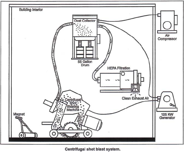
42
3.3 CENTRIFUGAL SHOT BLASTING
3.3.1 Description of Technology
Centrifugal shot blasting is a decontamination technology used to remove paint and light coatings from
concrete surfaces or to abrade concrete surfaces directly. Hardened steel shot is rapidly propelled at
contaminated surfaces to fracture the surface, resulting in small dust sized particles which can be
vacuumed and removed for proper disposal. Used shot is recycled by the system; lighter weight pieces that
become small through repeated use are removed from the system by the vacuum suction while those still
large enough to be reused are cycled back through. The diagram in Exhibit 3-2 shows a typical centrifugal
shot blast system.Unlike many decontamination technologies, shot blasting results in a relatively smooth
surface which can be recoated and reused (DOE 1998b; DOE 1999a).
Marketed by a variety of vendors, centrifugal shot blasting is electrically powered, and can remove light
coatings or concrete surfaces up to 0.5 to 1 inch deep, though it is ideal for removing surfaces between
1/16 and 1/8 inch in depth. A motorized blast wheel inside the system is supported by a booster motor and
fan. Once these components are running, shot is released into the system through a gate from a storage
hopper. The speed of the system, the size of the shot, and the amount released into the system can be
varied based on the degree of removal necessary. Gauges on the control panel of the unit tell an operator
when more shot needs to be added to the system and how fast the unit is moving. The amount of shot
released can be controlled by a panel switch, and toggle switches on the control panel are used to steer the
unit.
The shot blast unit relies on a dust collection system to remove abraded dust and particles and to reduce
airborne contaminants during the decontamination process. An air wash baffle system separates the
Exhibit 3-2.

43
reusable shot from the contaminants to cycle back into the system. Contaminant debris and recycled shot
too small to use is gathered in a collection drum attached to the dust collection system. In addition, a
HEPA filtration system, an air compressor, and a generator (125 kW) or power source are required to
operate the system. A magnetic roller is supplied to retrieve escaped shot from the system.
The system in operation requires three workers: one to operate the centrifugal shot blast unit, another to
use the magnetic roller to recapture escaped shot, and a third to assist in drum exchange in the
contamination system.
3.3.2 Target Contaminants
Centrifugal shot blasting is used in the general radiological decontamination of concrete surfaces,
including the removal of hazardous paint and light coatings due to contamination. As with other blasting
decontamination technologies, there is no inherent radiological/non-radiological specificity.
3.3.3 Applicable Media and Surface Characteristics
Centrifugal shot blasting can be used to decontaminate concrete surfaces by removing contaminants and
substrate and is particularly effective at removing paint and light coatings. This technology can be used on
uniform concrete surfaces that contain wire mesh, rebar, and floor drains, but it does not respond well to
concrete that contains riverine pebbles. It can grind down these surfaces by 1/16 to 1 inch and functions
well when removing thin layers, as it leaves a surface in reusable condition.
3.3.4 Waste Streams and Waste Management Issues
The presence of the vacuum filtration system significantly reduces the issue of dust contamination, and,
because the system operates without a liquid stream, the waste stream is minimal. The primary waste
stream usually includes a dusty mixture of paint chips and concrete, depending on the condition of the
surface prior to treatment, as well as spent shot. Secondary contributors to the waste stream include
personal protective equipment, HEPA filters, used shot (still of usable size, but contaminated), and any
other materials that might have been used during the decontamination process (damp rags, brushes, plastic
matting, etc.).
3.3.5 Operating Characteristics
Centrifugal shot blast systems may consist of as many as six separate units (DOE 1998b; DOE 1999a).
The main centrifugal shot blast unit can range in size from 50 inches x 16.5 inches x 43 inches to 72
inches x 80 inches x 34 inches. It can weigh from 650 pounds to 2,700 pounds, and it may have a cutting
width as large as 13 inches. Even in large systems, the main unit can be operated by one person and is
driven using a toggle switch to move it right, left, forward, or backward. Typically, the system requires
five additional units, including a dust collection system, a HEPA filtration system, an air compressor (for
larger units), a forklift, and a generator. The significant physical characteristics of these units are
summarized in Exhibit 3-3 below.

44
Exhibit 3-3. Physical Characteristics of Centrifugal Shot Blast Systems
System Size
(Inches)
Weight
(Pounds)
Other
Main Unit 50x16.5x43 to
72x80x34
650 – 2700 Cutting Width: Up to
13 in
Dust Collection 60x27x113.25 to
127x76x57
700 – 1800 -------------
HEPA Filtration 44x79x45 1000 HEPA filters can be
simply attached to
smaller dust
collection systems.
Air Compressor ------------- ------------- Required capacity
varies.
Forklift ------------- ------------- 5000 lbs – 8600 lbs
lifting capacity
125 kW Generator ------------- ------------- 60 – 100 amps
480 volts
Three phase
Source: DOE 1998b; DOE 1999a.
A magnetic roller is supplied to collect shot escaped from the system, and collection drums, ranging from
23 to 55 gallons in size, are required to gather dust and debris from the dust collection system. A dust hose
with a six-inch diameter and length ranging from 50 to 75 feet connects the dust collection system to the
main unit. Smaller units have a hopper that can accommodate about 100 pounds of steel shot, while larger
units can hold 800 pounds.
While only one person is required to operate the shot blast unit, at least two additional workers should be
on hand to change out dust collection drums as they become filled, to operate the forklift for set up, and to
use the magnetic roller to collect escaped shot. Personal protective equipment required to operate the
system may include coveralls, shoe covers, hoods, glove liners, gloves, ear plugs, hard hats, powered air
purifying respirators, breathing zone monitors, and a Personal Ice Cooling System (PICS). Minimal
training is required for operation. Certain OSHA and CFR requirements govern the operation of this
equipment and the disposal of its waste.
Centrifugal shot blasting units can be limited by their large size, as they can only get within two to six
inches of a floor and wall interface and within five inches of a corner. A decontamination device designed
to cover smaller surface areas, such as concrete grinder, might be used along with a shot blasting unit for
smaller decontamination areas.
3.3.6 Performance
Centrifugal shot blasting has been the subject of two in-depth demonstrations and analyses by the DOE
(DOE 1998b; DOE 1999a). The first demonstration compared a large shot blasting system as an
innovative technology against a rotary drum planer (baseline technology) at DOE’s Fernald
Environmental Management Project (FEMP) site in Fernald, Ohio. The second compared a much smaller
shot blast system against mechanical scabbling (the baseline technology) at the Argonne National
Laboratory-East (ANL) CP-5 Research Reactor.
45
Centrifugal shot blasting was compared to the baseline technologies with respect to its ability to:
• Remove coatings from concrete floors,
• Reduce the quantity of concrete that must be disposed of off site,
• Reduce the amount of secondary waste generated during the concrete removal process,
• Provide a cost-effective concrete decontamination process, and
• Provide a direct comparison to baseline concrete removal technologies.
The most important factor in evaluating the smaller centrifugal shot blast system was its effectiveness in
the removal of radiologically contaminated coatings (paint) from the surface of a concrete floor, leaving
the floor in reusable condition. This was accomplished successfully, in addition to significantly reducing
worker fatigue, exposure, and bringing the contamination to background levels. Some modifications to the
unit were required to improve overall stability and drum removal processes.
The larger shot blast system was used to determine the effectiveness of the system to remove concrete
surfaces at 1-inch depth. When compared to the baseline, the larger shot blast unit was able to work over
obstructions in the concrete, to maneuver in smaller areas, and to remove thin surface layers leaving the
floor in reuseable condition. Where this system fell short, however, was that it had trouble removing
concrete down to the required 1-inch depth, where the rotary drum planer easily accomplished this task. It
is important to note here that the concrete below the surface contained large numbers of riverine pebbles
which hindered the shot-blasting significantly.
In both cases, escaped shot from the system posed a significant hazard to workers. Even in contained areas
and despite precautions, escaped shot would often ricochet off walls and plastic used to contain the
demonstration and hit workers. Additionally, before it was collected by the magnetic roller, escaped shot
was dangerous to walk on and around, and presented a slipping hazard to those working with it.
The DOE studies provided a significant amount of the performance and cost data used in this profile.
Accordingly, the data should be used only as a guide, and the manufacturer should be contacted for
specific information on the technology’s performance.
Exhibit 3-4, below, provides the overall performance results of the Centrifugal Shot Blast Unit.

46
Exhibit 3-4. Performance Results of the Centrifugal Shot Blast Unit
Performance Factor Assessment
Productivity 310 ft /h for the smaller unit; 17.7 ft /h for the larger unit
22
Water Usage None
Ease of Use Vendor training required.
PPE Usage Required one set of PPE, and the larger unit required less hearing
protection than the baseline.
Primary Waste Significantly lower than baseline, particularly when comparing
the larger unit to the drum planer.
Secondary Waste Lower than baseline.
Airborne Contamination Lower than baseline due to presence of vacuum filtration system.
End Condition When concrete is of uniform consistency, leaves a smooth
reusable surface.
Source: DOE 1998b; DOE 1999a.
3.3.7 Capital and Operating Costs
DOE studies provide extensive cost analyses of centrifugal shot blasting for decontamination of debris in
the FEMP and ANL CP-5 Research Reactor demonstrations. Furthermore, additional cost information and
demonstration data are contained in the CP-5 Large Scale Demonstration Project, Technical Data for the
Concrete Cleaning, Inc. Centrifugal Shot Blast Technology 1997, which is available upon request from the
Strategic Alliance for Environmental Restoration. The studies caution that the analysis is only a limited
representation because it uses only data that were observed during the demonstration, and some of the
observed costs have been eliminated or adjusted to make the estimates more realistic.
The following cost elements were identified in advance of the demonstrations, and data were collected to
support a cost analysis based on these drivers:
• Mobilization (including cost of transporting equipment to the demonstration site and necessary
training),
• D&D work (including items such as the cost of labor, utilities consumed, supplies and the use of
equipment for washing debris),
• Waste disposal,
• Demobilization (including removal of temporary work areas and utilities, decontamination of
technology equipment, and removal from the site), and
• Personal protective equipment.
The study provides full details of the methodology and assumptions. Salient points are that equipment
costs were based on the cost of ownership. Hourly equipment rates were calculated using a standard U.S.
Army Corps of Engineers method. The fixed cost elements (i.e., those independent of the quantity of
D&D work, such as equipment mobilization) were calculated as lump sums. The variable cost elements
(i.e., those dependent on the quantity of D&D work, such as labor costs) were calculated as costs per unit
of D&D work performed.

47
The conclusions of the cost analysis for the large shot blasting unit vs. the rotary drum planer are given in
Exhibit 3-5, with unit costs provided where applicable. According to the study, equipment
decontamination caused demobilization costs to rise significantly for centrifugal shot blasting.
Exhibit 3-5: Conclusions of the Department of Energy Cost Analysis
Cost driver Rotary Drum Planer
(Baseline)
Centrifugal Shot Blasting
(Innovative)
Mobilization $3,386 $9,500
D&D work $4.30/ft $30.21/ft
22
Waste disposal $3.35/ft $2.23/ft
22
Demobilization $5,895 $6,195
PPE $1.79/ft $1.82/ft
22
Source: DOE 1998b; DOE 1999a.
The conclusions of the cost analysis for the smaller shot blasting unit versus mechanical scabbler are
given in Exhibit 3-6. The conclusions drawn from the demonstration indicate that the total cost for
centrifugal shot blasting is equal to that of the baseline technology at 1,900 square feet, and for areas
beyond that square footage, centrifugal shot blasting is less expensive than the baseline. Additionally, the
maintenance cost for machinery that might wear during the demonstration are significantly lower for the
shot blasting (0.03/square feet) as compared to the baseline (0.22/square feet).
Exhibit 3-6. Summary Cost Comparison Process-Enriched Uranium Material
Cost driver Mechanical Scabbler
(Baseline)
Centrifugal Shot Blasting
(Innovative)
Mobilization $4,308 $6,330
D&D work $3,240 $6,480
Waste disposal $1,655 $1,399
Demobilization $3,702 $8,432
PPE $46.33/day$1.79/ft $46.33/day
2
Source: DOE 1998b; DOE 1999a.

48
3.3.8 Commercial Availability
Mike Connacher, Owner
Concrete Cleaning, Inc.
5110 N. Ormond
Ohs Orchards, WA 99027
U.S.
Phone: (509) 226-0315
E-mail: con[email protected]

49
3.4 CONCRETE GRINDER
3.4.1 Description of Technology
The concrete grinder uses a diamond grinding wheel to decontaminate and strip concrete surfaces. The
light-weight hand-held device creates a smooth surface when applied to flat or slightly curved surfaces,
produces little vibration, and with a vacuum attachment, effectively removes dust created by the grinding
process (DOE 1998c). A picture of a concrete grinder appears in Exhibit 3-7. Exhibit 3-8 portrays a
worker using one.
Sold by C.S. Unitec, Inc., the Lightweight Concrete Grinder is
electrically powered. When used in a circular motion, it rapidly
grinds concrete surfaces 1.5 to 3 millimeters deep. A dust
collection shroud can is designed to attach to the vacuum hose of
an on-site HEPA filtration system, and the vacuum filtration system is required for grinder use. The
diamond grinding wheel has external shroud holes which allow air intake to cool the working blades. Air
taken in by the external shrouds passes into the internal discharge holes which feed to the vacuum
filtration system.
The technology requires one person for operation and is considered effective for the decontamination and
stripping of concrete. It is quick and easy to use compared to similar technologies.
3.4.2 Target Contaminants
Concrete grinding is used for more general radiological decontamination of concrete surfaces or for hot
spot decontaminations of concrete surfaces. Non-radiological decontamination uses include deep-cleaning
and concrete resurfacing due to the smooth finish the device produces.
3.4.3 Applicable Media and Surface Characteristics
Concrete grinding can be used to decontaminate interior and exterior flat or slightly curved concrete
surfaces, particularly floors and walls. It can grind down these surfaces 1.5 to 3 millimeters in ambient
temperatures ranging from 3 to 40°C.
Exhibit 3-7.
Concrete Grinder in Use
Exhibit 3-8.
50
3.4.4 Waste Streams and Waste Management Issues
The presence of the vacuum filtration system significantly reduces the issue of dust contamination, and,
because the system operates without a liquid stream, waste streams created are minimal. Additional
contributors to the waste stream include personal protective equipment, plastic wrapping and sleeving for
vacuum hoses, and the concrete dust collected by the vacuum. The fee for waste disposal is minimal.
3.4.5 Operating Characteristics
The system consists of one unit. Because it is hand-held, it is totally portable, limited only by the hose and
power cord length. Typical concrete grinders weigh 6 pounds. The diamond grinding wheel is 5 inches
(12.7 centimeters) in diameter. When in motion, it spins at 10,000 rpm and needs to be replaced after
approximately ten hours of grinding (though this estimate is heavily based on wear on the wheel and the
removal rate of the grinding). The vacuum port is 1.25 inches (3.2 centimeters) in diameter. There are
internal and external air intakes which cool the system and reduce dust feed into an attached vacuum hose.
The motor operates at 110 VAC, is rated at 11 amps, and can be plugged into any standard electrical
outlet. The depth of grinding is affected by the number of passes and the amount of time spent on any
given area.
The system takes about five minutes to set up, assuming a vacuum filtration system is in place. As part of
set up, users should check the freewheel spin of the grinding wheel, ensure that the power cords and
connectors are free of cuts or signs of wear, connect the vacuum hose and power cord, and proceed with
any required safety checks.
Although the grinder can be operated by one person, it is helpful to have a second on hand to monitor the
vacuum filtration system and to make sure hoses stay attached and in place. Personal protective equipment
required to operate the system includes an air purifying respirator, face shield, booties, coveralls, double
coveralls (5 percent of the time), hood, pairs of inner and outer gloves and glove liners, and rubber
overshoes. Minimal to no training is required for operation. While normal safety procedures should apply
when workers operate this equipment, no special regulatory or permit requirements exist in order for it to
be used.
The effectiveness of concrete grinders can be limited by their size, and it may be advantageous to use
them with other decontamination technologies. A decontamination device designed to cover large surface
areas such as pneumatic scabbler might be used along with a grinder, whereas floor and wall interfaces
might require a device designed for difficult crevices, such as an air-driven needle gun.
3.4.6 Performance
Concrete grinding has been subject of an in-depth demonstration and analysis by the Department of
Energy (DOE 1998c) where it was compared with a pneumatic scaler and single-piston scabbler, the latter
two being regarded as the baseline technology. The technologies were demonstrated at the DOE’s C
Reactor Interim Safe Storage (ISS) Project as part of the Large Scale Demonstration and Deployment
Project (LSDDP) at the Hanford Site in Richland, Washington.

51
The objectives of the LSDDP were that, compared to the baseline scabbler and scaler, the grinder should
demonstrate:
• Capability at grinding floors and walls 1.5 to 3 millimeters deep,
• Operations at ambient temperatures from 3 to 40°C,
• Decontaminations using conventional equipment, and
• Safety to those operating the device.
The DOE study provided a significant amount of performance and cost data used in this profile. However,
the data should be used only as a guide, and the manufacturer should be contacted for specific information
on the technology’s cost.
The overall performance results of the concrete grinder are given in Exhibit 3-9 below.
Exhibit 3-9. Performance Results for the Concrete Grinder
Performance Factor Comparison to Baseline
Productivity and Work Hours Concrete Grinder: an average of 4.5m /h @ 1.5 mm removal
2
depth
Scabbler: 1.13 m /h @ 1.5 to 3 mm removal depth
2
Scaler: 1.1 m /h @ 1.5 mm removal depth
2
Decontamination Effectiveness Effective in decontaminating the surface to below release levels
PPE Usage Same as baseline
Secondary Waste Less dust than baseline as the depth of surface removal is easier
to control
Temperature Considerations Same as baseline; performs at ambient temperatures between 3
and 40°C
Worker Safety Because it is more efficient than the baseline technologies, the
Concrete Grinder reduced worker exposure to contaminants, and
vibration. It also weighs less.
Source: DOE 1998c.
3.4.7 Capital and Operating Costs
The Department of Energy study provides an extensive cost analysis of concrete grinding for
decontamination of concrete surfaces in the LSDDP demonstration. The study cautions that the analysis is
only a limited representation because it uses only data that were observed during the demonstration, and
some of the observed costs have been eliminated or adjusted to make the estimates more realistic.
The following cost elements were identified in advance of the demonstrations, and data were collected to
support a cost analysis based on these drivers:
• Mobilization (including cost of transporting equipment to the demonstration site and necessary
training),
• D&D work (including items such as the cost of labor, utilities consumed, replacement parts),
• Waste disposal,

52
• Demobilization (including removal of temporary work areas and utilities, decontamination of
technology equipment, and removal from the site), and
• Personal protective equipment (including replacement costs of disposable items).
The study provides full details of the methodology and assumptions. Salient points are that equipment
costs were based on the cost of ownership. Hourly equipment rates were calculated using a standard U.S.
Army Corps of Engineers method. The variable cost elements (i.e., those dependent on the quantity of
D&D work, such as labor costs) were calculated as costs per hour of D&D work performed.
The conclusions of the cost analysis are given in Exhibit 3-10 and Exhibit 3-11.
Exhibit 3-10. Department of Energy Cost Comparisons
Cost driver
Concrete Grinder
(Innovative)
Pneumatic Scaler
(Baseline)
Pneumatic Scabbler
(Baseline)
Mobilization $1,293 $1,339 $1,391
D&D work $1,592 $4,198 $4,101
Waste disposal $404 $404 $404
Demobilization $749 $750 $761
PPE $94.36 $94.36 $94.36
Source: DOE 1998c.
Exhibit 3-10 is based on removing surfaces of concrete walls to a depth 1.5 millimeters for the concrete
grinder and the scaler, and 1.5 to 3 millimeters for the scabbler.
Exhibit 3-11. Summary of Unit Costs
Cost Estimates Concrete Grinder
(Innovative)
Pneumatic Scaler
(Baseline)
Pneumatic Scabbler
(Baseline)
Production Rate
4.5 m /h
2
(48 ft /h)
2
1.11 m /h
2
(11.8 ft /h)
2
1.13 m /h
2
(12 ft /h)
2
Unit Cost $31.43/m ($2.92/ft )
22
$112.70/m
2
($10.47/ft )
2
$111.62/m
2
($10.37/ft )
2
Source: DOE 1998c.
53
3.4.8 Commercial Availability
CS Unitec
22 Harbor Ave.
Norwalk, CT 06850
U.S.
Phone: (203) 853-9522
Phone: (800) 700-5919
Fax: (203) 853-9921
E-mail: info@csunitec.com
http://www.csunitec.com
Andrews Machinery Construction
1757 First Ave. South
Seattle, WA 98134
U.S.
Phone: (206) 622-1121

54
3.5 CONCRETE SHAVER
3.5.1 Description of Technology
The concrete shaver is an electrically driven, self-propelled system capable of removing contaminants
from concrete floors. It is considered an attractive alternative to the traditional hand-pushed, multi-piston
pneumatic scabbler on wheels (DOE 1998d). A picture of one appears in Exhibit 3-12.
The cutting head of a concrete shaver is a drum that contains embedded diamonds. It is controlled by the
operator from the handles. In the Marcrist-patented model, the machine is fitted with a 25-centimeters (10-
inches) wide by 12.7 centimeters (5- inches) diameter
shaving drum, onto which diamond-impregnated blades
are fitted. The number of blades chosen is dependent
upon the surface finish required. One set of shaver blades
is rated for 156 hours of operation. The design for
mounting the blades on the drum results in low vibration
levels.
The concrete shaver can achieve variable shaving depths
from 0.01 centimeters (0.004 inches) to 1.3 centimeters
(0.5 inch). The depth of shaving is set by the use of a
manual rotary wheel that is linked to a digital display.
The unit weighs 150 kilograms (330 pounds), consumes
16 amps of 380-volt to 480-volt, 3-phase power, and has
forward and reverse action. The system can operate in
ambient temperatures from 3 C to 40 C (37 F to 104
0 0 0 0
F). Commercially available concrete shavers are well
suited for large, wide-open concrete floors and slabs.
3.5.2 Target Contamination
Concrete shavers are used in the general decontamination of concrete surfaces and for large areas or “hot
spots” on floors. They are effective against radiological contaminants and paints. However, as with other
physical decontamination technologies, there is no inherent radiological/non-radiological specificity.
3.5.3 Application Media and Surface Characterization
The technology can be used to decontaminate concrete floors and slabs that are generally planar or
slightly curved. It can be used on both interior and exterior surfaces. The self-propelled, electric-powered
concrete shaver is particularly useful on large, flat, wide-open areas. Due to the physical size and
geometry of the concrete shaver, it is not appropriate for use on very small concrete floors and slabs or
those with a significant number of obstructions.
Exhibit 3-12.
55
3.5.4 Waste Stream and Waste Management Issues
The presence of the vacuum filtration system significantly reduces the issue of large amounts of dust
contamination. Nevertheless, the amount of concrete dust generated by the concrete shaver is slightly less
than multi-piston pneumatic scabbler. Also, because the system operates without a liquid stream, the
waste stream is minimal. The primary waste stream usually includes a dusty mixture of paint chips and
shaved concrete, depending on the conditions of the surface prior to treatment. Personal protective
equipment is a secondary contributor to the waste stream. The use of HEPA filters, personal protective
equipment, and vacuum systems significantly reduces worker exposure to dust.
3.5.5 Operating Characteristics
The descriptions of the operating characteristics, performance, and costs of the concrete shaver in this and
the next two sections are based on an in-depth demonstration and analysis by the U.S. Department of
Energy to measure performance and costs against a baseline technology, the multi-piston pneumatic
scabbler. The test was conducted at Sample Rooms X and Y at the Hanford C Reactor building during
1997 using a Marcrist Industries shaver. For dust-free operation, a vacuum extraction system was also
used. Demonstration of the baseline technology, the scabbler, was conducted at Sample Room A and B at
the C Reactor building. Onsite decontamination and decommissioning (D&D) workers instructed by the
vendor Marcrist Industries conducted the demonstration (DOE 1998d).
The Marcrist Industries concrete shaver uses a diamond cutting head roller that rotates towards the front
of the device. The cutting head is enclosed in a metal pan to prevent thrown blades from hitting the
operator. Also, the cutting blades can be configured in several ways allowing different modes of removal.
It is important that the cutting head be kept above the floor surface while starting the unit. The cut can be
set up for a depth of from 0.1 to 15 millimeters for each pass, and the depth of the cut can easily be set at
the handle by turning a control knob. The greater the depth on each pass, the rougher the finished surface.
The width of the cut can also be adjusted. For this test, the widest available cut was performed,
approximately 250 millimeters.
The concrete shaver can operate from a slow crawl up to the speed of a moderate walk, giving a high
production rate. Once engaged, it can continue shaving while moving forward without the operator. A
knob on the side of the device controls the speed of the unit, which remains constant until readjusted.
3.5.6 Performance
The DOE demonstration (DOE 1998d) compared the concrete shaver as an innovative technology against
the baseline technology air-powered scabbler. The scabbler is a walk-behind, push-type device with five
piston heads. It is designed to remove concrete surfaces between 0.3 cm (1/8 inch) and 0.6 centimeters
2
(1/4 inch) from large areas. A single pass with this tool on an area of 3.0 cm (11.5 in ) delivers 1,200
22
piston strikes per minute to the concrete surface.
The DOE conducted the analysis in order to determine if the concrete shaver was:
• Capable of removing radiologically contaminated concrete using the diamond shaving technology,
• Compatible with a dust collection shroud that may be attached to an existing onsite high-
efficiency particulate HEPA filtration system,
• Useful with commonly available electric power,

56
• Able to remove 3 millimeters (1/8-inch) depth of potentially contaminated concrete,
• Able to handle steel-reinforcing bar and piping that may be imbedded in the concrete being
decontaminated,
• Able to operate in ambient temperatures from 3 C to 40 C (37 F to 104 F), and
000 0
• Able to address the lead-based paint contamination in the sample rooms which required from 1.5
to 3 millimeters (1/16 inch to 1/8 inch) of concrete removal from floors in wide areas and up to 6
millimeters (1/4 inch) removal in small areas.
The results of the project concluded that the concrete shaver was more effective then the scabbler in
removing radiologically contaminated material from the concrete floors than the scabbler. The shaver
decontaminated approximately 76 square meters (816 square feet) of floors in Sample Rooms X and Y at
the Hanford C Reactor Building southeast work area, removing 3 millimeters (1/8 inch) depth from the
concrete surfaces. The major difference in productivity between the shaver and the scabbler is related to
the removal methodology each employ. With the floor shaver, the diamond-bit drum enables single-pass
cutting at precise depths while minimizing and containing the waste generated. The scabbler is neither as
precise nor as fast as the floor shaver since it essentially works on a carbide-tipped bit hammer-blow
principle. After making a pass with the scabbler, the resulting floor surface is left rough and irregular and
not always cut to the proper depth. This forces the operator to decrease the speed of the device and rework
areas. The reworking also means more concrete waste is generated, thus, increasing disposal costs.
In summary, the shaver provided the following advantages:
• It left a smoother surface than the scabbler, so final release surveying was more reliable.
• It removed the concrete surfaces much faster than the scabbler by a factor of almost five (11.9
m /h [128 ft /h] vs. 2.5 m /h [27 ft /h] at 3 millimeters [1/8 inch] depth).
22 22
• It operated with less vibration.
• It abraded embedded steel in addition to concrete.
• It showed no visible wear after removing 0.3 centimeters (1/8 inch) depth of concrete from the
two sample rooms.
The diamond blades of the shaver are estimated by the manufacturer to be good for removing 0.3
centimeters (1/8 inch) depth from 1,800 square meters (20,000 square feet) of concrete surface areas. This
would be equivalent to over three times the hours of usage between blade changes versus bit changes for
the baseline scabbler.
3.5.7 Capital and Operating Costs
The Department of Energy study (DOE 1998d) provides a cost analysis of concrete shaver technology.
The operating costs for the concrete shaver technology are $14.21/square meters ($1.32/square feet)
versus $43.60 square meters ($4.05 square feet) for the baseline scabbler. Exhibit 3-13 provides a
comparative view of the costs of the two technologies. The exhibit shows only elemental costs; other
costs, such as those associated with mobilization, waste disposal etc. are not included.

57
Exhibit 3-13. Production Rates and Unit Costs (1997)
Concrete Shaver Pneumatic Scabbler
Cost Element Production
Rate
Unit Cost
($)
Cost Element Production
Rate
Unit Cost
($)
Removing 0.3 cm
(1/8 in) of
concrete
11.9 m /h
2
(128 ft /h)
2
14.21/m
2
(1.32/ft )*
2
Removing 0.3
cm (1/8 in) of
concrete
2.52 m /h
2
(27 ft /h)
2
43.60/m
2
(4.05 ft )
2
Replacement
blades for the
(Marcrist)
concrete floor
shaver
1 set/1800 m
2
(20,000 ft ) of
2
concrete shaved
or 1 set/156 hs
7172.00/set
(for normal
concrete)
Replacement
bits for the
floor scabbler
1 set/113 m
2
(1215 ft ) of
2
concrete scabbled
or 1 set/45 hs
480.00/set
(for normal
concrete)
*Unit cost includes blade wear cost; blade life is estimated at 1860 m for removing 0.3 cm (1/8 in) depth of concrete
2
or 156 hours of use.
This technology demonstration indicated that the shaver saved approximately 50 percent in cost over the
baseline scabbling technology. The cost savings resulted from three factors:
• Labor savings from increased productivity realized with the concrete shaver
• The longevity of concrete shaver blades as compared to the scabbling tools, and
• The generation of less waste.
The significance of each of these factors may vary from site to site.
3.5.8 Commercial Availability
The Marcrist Industries
Sandall Stones Rd.
Kirk Sandall Industrial Estate
Doncaster, South Yorkshire, DN31QR
United Kingdom
Phone: +44 (0) 1302 890 888
58
3.6 CONCRETE SPALLER
3.6.1 Description of Technology
The concrete spaller is used to decontaminate and strip both slightly curved and flat concrete surfaces
(DOE 1998e). It is effective in large areas, and it is a good tool for hot-spots and in-depth decontamination
of cracks in concrete. It can also be used to gather samples of concrete to be tested. Although the result is
an uneven surface, the advantage of the spaller is that it can decontaminate more rapidly than other
technologies at 3 millimeters or greater surface depth.
With a patented bit designed by Pacific Northwest National Laboratory, the spaller is powered by a 9-ton
hydraulic cylinder. Holes are drilled in the concrete surface to be decontaminated in a honeycomb pattern,
and the spaller bit is inserted into a drilled hole. The four-way hydraulic valve on the hydraulic pump is
then turned on, and the bit expands in the hole causing the spalling. Chunks of concrete resulting from the
spalling are up to 5 millimeters thick and 18 to 41 centimeters in diameter and are captured by a metal
shroud which is attached around the spaller. A detachable shroud includes a vacuum port which will allow
a hose to connect to an on-site HEPA filtration system if dust control is necessary.
The technology requires two people for operation. The process of predrilling the holes in the surface to be
spalled is most time consuming. Each hole takes 10 to 40 seconds to drill on 20 centimeters (8 inches)
centers.
3.6.2 Target Contaminants
Concrete spalling is used for deeper radiological decontamination of large areas of concrete surface, the
decontamination of concrete cracks, or for hot spot decontaminations of concrete surfaces. Non-
radiological decontaminant uses include concrete sampling.
3.6.3 Applicable Media and Surface Characteristics
Concrete spalling can be used to decontaminate interior and exterior flat or slightly curved concrete
surfaces, particularly floors and walls, and can work around piping or reinforcements embedded in the
concrete. It can spall these surfaces 3 millimeters deep or greater, in ambient temperatures ranging from 3
to 40°C. It leaves behind a rough, uneven surface sufficiently decontaminated for demolition.
3.6.4 Waste Streams and Waste Management Issues
Since it is designed to remove large chunks of concrete from surfaces at depth, the concrete spaller leaves
a larger volume of waste than other decontamination technologies. The presence of a vacuum filtration
system reduces the amounts of airborne contamination generated, and a water spray may be used on
surfaces prior to drilling if the concrete is alpha/beta contaminated. Additional contributors to the waste
stream include personal protective equipment, plastic wrapping and sleeving for vacuum hoses, and the
concrete dust collected by the vacuum.

59
3.6.5 Operating Characteristics
The concrete spaller system consists of one unit. It is hand-held and portable and weighs 13.6 kilograms
(30 pounds). A sling is recommended to help support the unit and ease operator strain. The steel spalling
bit contains an internal-tapered sliding push rod; removable sheet metal shroud for dust and fragment
control with a viewing window and vacuum port; a hydraulic cylinder (9 tons); a handle extension for the
hydraulic cylinder; hoses to connect the pump and cylinder; and an electric/hydraulic pump (19.5 amp,
110 volt, 50 kilograms or 108 pounds, rated at 10,000 psi). The push rod connects to the hydraulic piston
rod with a screwed coupling. It expands the bit as it moves through an opening in the end of the bit. The
rod then pushes against the bottom of the pre-drilled hole, enabling the bit to back out of the hole slightly
while it expands. The expansion breaks the concrete apart. The depth of spalling is related to pilot hole
spacing, and 5 centimeters deep holes (to limit bit breakage) are recommended. Holes 2.54 centimeters (1
inch) in diameter are typically drilled in a triangular or honeycomb pattern on 20-centimeter (8 inches)
centers. The spaller performs best when removing surfaces of 3 millimeters (1/8 inch) depth or greater.
The system takes about five minutes to set up and requires a user to connect hoses to the hydraulic
cylinder, check the power cords and connectors for cuts or signs of wear, connect the vacuum hose and
power cord, and ready a water sprayer if one is required for the predrilling of the holes. Additional safety
checks may be required depending on site conditions. A longer preparation time is required to predrill the
holes (estimated at 10-40 seconds/hole), and the number of holes necessary depends on the size of the area
to be spalled.
The system requires two people for operation, unless an electrically operated valve can control the
hydraulic pump from the spaller handle. Vibration and noise from the system is minimal, and no hearing
protection is required. Personal protective equipment required to operate the system includes an air
purifying respirator, face shield, booties, coveralls, double coveralls, hood, pairs of inner and outer gloves
and glove liners, and rubber overshoes. Minimal training is required for operation. While normal safety
procedures should apply when workers operate this equipment, there exist no special regulatory or permit
requirements in order for it to be used.
Concrete spallers can be limited by their size, and it may be more effective at times to use them with other
decontamination technologies. A decontamination device designed to cover large surface areas might be
used along with a spaller for more efficient decontamination. Floor and wall interfaces might require a
device designed for difficult crevices, such as an air-driven needle gun.
3.6.6 Performance
Concrete spalling has been subject of an in-depth demonstration and analysis by the Department of Energy
(DOE 1998e) in which it was compared with a pneumatic scaler and single-piston scabbler, the latter two
being regarded as the baseline technologies. The technologies were demonstrated at the Department of
Energy’s C Reactor Interim Safe Storage (ISS) Project as part of the Large Scale Demonstration and
Deployment Project (LSDDP) at DOE’s Handford Site in Richland, Washington. The demonstration
objectives were that compared to the baseline scabbler and scaler, the spaller should demonstrate:
• Capability at grinding floors and walls, up to 3 millimeters deep,
• Operations at ambient temperatures from 3 to 40°C,
• Decontaminations using conventional equipment, and
• Safety to those operating the device.

60
The DOE study provided a significant amount of performance and cost data used in this profile.
Accordingly, the data should be used only as a guide, and the manufacturer should be contacted for
specific information on the technology’s cost.
The overall performance results of the concrete spaller are given in Exhibit 3-14 below.
Exhibit 3-14. Performance Results of the Concrete Spaller
Performance Factor Assessment Compared with Baseline
Productivity and Work Hours Concrete Spaller: an average of 1.3 m /h
2
Scabbler: 1.11 m /h
2
Scaler: 1.10 m /h @ 1.5 mm removal depth
2
Decontamination Effectiveness Effective in decontaminating the surface to below release levels.
PPE Usage Approximately the same as baseline
Secondary Waste Very little dust generation with the exception of drilling, for
which dust should be controlled. Large chunks of concrete
generated
Temperature Considerations Same as baseline; performs at ambient temperatures between 3
and 40°C
Worker Safety Comparable exposure time to baseline, but less airborne
contamination is less
Source: DOE 1998e.
3.6.7 Capital and Operating Costs
The Department of Energy study (DOE 1998e) provides an extensive cost analysis of concrete spalling for
decontamination of concrete surfaces in the LSDDP demonstration. The study cautions that the analysis is
only a limited representation because it uses only data that were observed during the demonstration, and
some of the observed costs have been eliminated or adjusted to make the estimates more realistic.
The following cost elements were identified in advance of the demonstrations, and data were collected to
support a cost analysis based on these drivers:
• Mobilization (including cost of transporting equipment to the demonstration site and necessary
training),
• D&D work (including items such as the cost of labor, utilities consumed, replacement parts)
• Waste disposal,
• Demobilization (including removal of temporary work areas and utilities, decontamination of
technology equipment, and removal from the site), and
• Personal protective equipment (including replacement costs of disposable items).
The study provides full details of the methodology and assumptions. Salient points are that equipment
costs were based on the cost of ownership. Hourly equipment rates were calculated using a standard U.S.

61
Army Corps of Engineers method. The variable cost elements, those dependent on the quantity of D&D
work, such as labor costs, were calculated as costs per hour of D&D work performed.
The conclusions of the cost analysis are given in Exhibit 3-15 and Exhibit 3-16.
Exhibit 3-15. Department of Energy Cost Comparisons
Cost driver
Concrete Spaller
(Innovative)
Pneumatic Scaler
(Baseline)
Pneumatic Scabbler
(Baseline)
Mobilization $837.21 $1,293.99 $1,348.37
D&D Work $4,386.28 $4,263.48 $4,289.84
Waste Disposal $403.60 $403.60 $403.60
Demobilization $121.91 $754.32 $767.34
PPE $94.36/day $94.36/day $94.36/day
Source: DOE 1998e.
The following exhibit is based on removing surfaces of concrete walls to a minimum depth of 3
millimeters as demonstrated.
Exhibit 3-16. Summary of Unit Costs
Cost Estimates
(Unit Cost)
Concrete Spaller
(Innovative)
Pneumatic Scaler
(Baseline)
Pneumatic Scabbler
(Baseline)
Drill Holes
$142 m /h
2
(13.16 ft /h)
2
N/A N/A
Decontaminate Wall
$58/m
2
($5.41/ft )
2
$155/m
2
($14.4/ft )
2
$156/m
2
($14.5/ft )
2
Unit Cost
$200/m
2
($18.52/ft )
2
$155/m
2
($14.4/ft )
2
$156/m
2
($14.50/ft )
2
Source: DOE 1998e.
Although the data in this exhibit reflect a performance cost higher than that of the two baseline
technologies, the inexperience of the crew and an ineffective drill at the time of the demonstration raised
the cost significantly. The study estimates that under optimum conditions, the spaller will actually save a
user 15 percent as compared to the two baseline technologies.

62
3.6.8 Commercial Availability
Pacific Northwest National Laboratory
P.O. Box 999
Richland, WA 99352
U.S.
Phone: (509) 372-4069 (Mark Mitchell)

63
3.7 DRY ICE BLASTING
3.7.1 Description of Technology
2
Dry ice blasting, or carbon dioxide (CO ) blasting, is an industrial cleaning process for surfaces that uses
carbon dioxide pellets as the blasting medium (Renard 1997; May 2003). Carbon dioxide pellets (Exhibit
3-17) are about 1-3 millimeters in size but may be as
long as about 4.5 millimeters. The pellets are very cold
(below minus 100°F).They are housed in a machine
where they are typically accelerated by compressed air
with pressures in the range of 100 – 150 psi, although
lower and higher pressures of up to 300 psi may be used
in certain circumstances. To remove the contamination,
the pellets are fired at a contaminated surface.
In dry ice blasting, contamination is removed by three
mechanisms which occur nearly simultaneously. In the
first mechanism, the accelerated carbon dioxide pellets
drive the contamination off of the surface because of
their impact at high velocities. This mechanism of
removal is similar to that of sandblasting. In the second
mechanism, the cold pellets create a thermal differential
with the contaminant material and the surface. This thermal differential may cause the contaminant and
the surface to contract at different rates, thereby weakening the bond between them. In the third
mechanism, the carbon dioxide pellets lift the contamination off of the surface when they expand into a
vapor. This expansion occurs when the pellets are
exposed to room temperature and when they collide with
the surface. The carbon dioxide gas rapidly expands,
and, as it does, it lifts the contamination off of the
surface.
Dry ice blasting machines are commercially available,
and the Department of Energy (DOE) and its contractors
have also modified a system for DOE needs. A company
called Cold Jet offers several different models and a full
range of supplies and accessories. The vendor
CryoGenesis sells some Cold Jet equipment, and it also
sells blasting systems made by Alpheus and robotic
systems (remote operated systems) of its own design . At the Savannah River Site, contractors for DOE
tested an Alpheus MiniBlast Model PLT-5X (Exhibit 3-18) which they modified for their use (May 2003).
Contractors for DOE have also tested in part a remote operated dry ice pellet decontamination system built
by CryoGenesis, which DOE had planned to use for decontamination work at Oak Ridge National
Laboratory and at the Hanford site (Renard 1998).
In general, the dry ice blasting machines work by delivering compressed air and the pellets to a nozzle
which may be directed at the surface of interest. The machines are either electric or pneumatic, and they
store the pellets for use. The rate of pellet delivery may be adjustable. Some machines use one hose,
delivering the pellets and high-pressure air down the same path. Other machines use two hoses with the
Exhibit 3-17.
Exhibit 3-18.
Typical Pellets - 1'8" diameter, approximately
1/16"-3/16" long
Alpheus MiniBlast Model PLT-5x
TM
64
first using transport air of about 40 psi to carry the pellets and a second hose to delivering the high-
pressure air to the nozzle gun where the pellets and high-pressure air are combined.
2
All of these machines operate on the principle that the CO gas returns to the atmosphere and leaves only
the contaminant and particles removed from the surface as waste. Therefore, they are usually used with
2
other systems that filter the CO gas and collect the waste material. For blasting in radioactive
environments, DOE reports that it would use support systems such as an air compressor, air dryer, and
containment hut with a HEPA filtered ventilation system. In designing the remote operated blasting
system, DOE and its contractors developed a separate vacuum system to collect the dislodged contaminant
particles. In general, dry ice blasting requires superior off-gas treatment systems and has been described as
slow.
3.7.2 Target Contaminants
Dry ice blasting targets surface contaminants and particulates. According to the vendor Cold Jet, its dry
ice blasting systems are designed to remove excess grease, sludge, sealant and weld slag. Their systems
have also been used to remove smoke, soot, vaporized synthetic resins, and char. The vendor further
claims that its dry ice blasting process can remove 100 percent of mold spores from wood. CryoGenesis
advertises the removal of resins, glues, food wastes, and fire and smoke residue from damaged materials.
When DOE tested the Alpheus MiniBlast Model PLT-5X, the target contaminant was cesium-137 applied
from a cesium nitrate solution. However, as with other physical decontamination technologies, there is no
inherent radiological/non-radiological specificity to dry ice blasting.
3.7.3 Applicable Media and Surface Characteristics
Vendors of dry ice blasting services and equipment claim that the technology is effective on a variety of
materials, including cement, concrete, plastic, wood, stainless steel, and other metals. DOE experience
with the technology yielded reasonable success on stainless steel, although methods of contaminant
deposition and the way the blasting equipment was operated did affect the efficiency of contaminant
removal. Preliminary DOE testing of the remotely operated blasting system suggests that the system
should be successful on concrete. However, no specific information was found on how irregularities in the
surface or the composition of the media might affect the efficiency of contaminant removal.
3.7.4 Waste Streams and Waste Management Issues
No significant waste stream or waste management issues were noted in the DOE tests, and the vendors do
not report any specific waste concerns. It is important to note, however, that, in both DOE tests, systems
and procedures were in place for the efficient collection of particulates and gas. As mentioned previously,
2
all of these machines operate with the idea that the CO gas returns to the atmosphere through a HEPA
filter and leaves only the contaminant and particles removed from the surface as waste streams.
Nevertheless, separate systems must be in place to filter the carbon dioxide gas and to contain and collect
waste materials, especially when dealing with radioactive substances.

65
3.7.5 Operating Characteristics
The basic principles of operation have been described previously. Characteristics of importance are noted
below:
• Air pressures of 100 – 150 psi are typical, although 300 psi pressure is available in some
machines.
• Low pressure machines (20 – 40 psi) are available.
• Blast pressure is typically adjustable.
• Rate of pellet delivery is variable on some machines.
• Nozzle type may vary from machine to machine, but no reports of nozzles with variable settings
were found.
• Dry ice blasting equipment may be stationary, mounted on carts, or available as a remote operated
unit.
• The machines can be operated by one person.
• Separate systems and equipment (containment hoods or enclosures; HEPA filters; vacuums; etc.)
2
are necessary to contain and collect CO gas and wastes.
3.7.6 Performance
Preliminary DOE testing of the CryoGenesis (Renard 1997) remote operated system yielded reasonable
results, but data on actual removal capabilities of radioactive materials seems limited to the results of the
DOE test with the Alpheus MiniBlast Model PLT-5X (May 2003). In that test, cesium-137 was applied
two ways to stainless steel: directly (cesium nitrate solution applied to the stainless steel and dried) and
indirectly (cesium-137 volatilized and condensed onto the stainless steel). In the case of the indirectly
applied contamination, dry ice blasting removed the cesium below the design requirements of the test in
all cases. However, the dry ice blasting did not meet the design requirements in five of 11 cases when the
cesium-137 was applied directly to stainless steel.
In addition, a statistical analysis of the results indicated that the following factors could influence the
efficiency of the dry ice blasting contaminant removal process:
• As blast pressure increases, the amount of removed contamination increases.
• Increases in nozzle standoff, the distance of the nozzle from the surface, decrease contamination
removal.
• Increases in travel speed, the rate at which the nozzle passes over the surface, decrease
contamination removal.
Changes in pellet rate delivery did not produce statistically significant changes in contamination removal.
Other factors such as the orientation of the nozzle with regard to the surface and the configuration of the
pellet delivery system were not evaluated.
3.7.7 Capital and Operating Costs
No reliable information on costs was available for this technology.

66
3.7.8 Commercial Availability
CryoGenesis
Units N1/N2
Riverside Industrial Estate
Little Hampton, West Sussex BN175DF
United Kingdom
Phone: +44 (0) 1903 731 717
Fax +44 (0) 1903 731 933
E-mail: cliv[email protected]m
http://www.cryogenesis.com
Cold Jet, LLC
455 Wards Corner Rd.
Loveland, Ohio 45140
U.S.
Phone: (513) 831-3211
Fax: (513) 831-1209
E-mail: info@coldjet.com
http://www.coldjet.com
67
3.8 DRY VACUUM CLEANING
3.8.1 Description of Technology
Dry vacuuming has been used effectively in radiological surface decontamination of building surfaces,
floors, beams, stairs, and other solid media. The decontaminated areas are then wet-wiped. Generally, no
wastewater is generated. The goal is to render concrete and steel as non-hazardous, so that the structures
can either be used for normal occupancy or demolished without creating vast amounts of hazardous wastes
(DOE 1994; DOE 1997).
Dry vacuum cleaning uses a commercial or industrial grade vacuum with a High Efficiency Particulate Air
(HEPA) filter to remove dust and particles from building and equipment surfaces. The vacuum uses
suction to draw air and loose surface particles into the storage body of the vacuum unit. Exhaust air passes
through a HEPA filter before being vented back to the atmosphere. The HEPA filters trap dust and debris
to protect against airborne contamination and to prevent recontamination of the air and surfaces just
vacuumed. Depending on the nature of the contamination, the dry vacuuming process often occurs in a
containment structure, which may consist of two layers of reinforced nylon tied to a self-supported,
reusable framework. The floors, walls, and ceiling are often one piece or are sealed to prevent the escape
of contaminants. Tents may have zippered doors.
HEPA vacuuming is ideal for the decontamination of surfaces with loose contamination. The filters
remove a minimum of 99.97 percent of particulates larger than 0.3 microns. In some commercial models,
the HEPA filter is integrated into a “bag-in/bag-out glove-box” assembly that permits removal of spent
filters directly into sealable, disposal bags without exposure to the atmosphere.
Dry vacuuming removes only loose particles, and no fixed surface or subsurface contamination is
removed. Thus, dry vacuuming may be used as an initial treatment method, possibly followed by another
technology for further treatment to reach desired protection levels.
3.8.2 Target Contamination
Dry vacuuming is typically used for the physical removal of contaminated particles from bare and coated
concrete surfaces. It can be used to remove lead-based paint chips, PCB-contaminated particles, asbestos,
and other fine hazardous and radioactive material, but it is applicable only to contamination in the form of
small, loose particles.
3.8.3 Application Media and Surface Characterization
Dry vacuuming is particularly effective at removing loose contaminants from surfaces. It should not be
used on porous surfaces, as loosely deposited materials may be pushed deeper into the surface.
3.8.4 Waste Stream and Waste Management Issues
Dry vacuuming operates without any liquids, and the waste stream is minimal. Depending upon the
condition of the surface before treatment, the primary waste stream usually consists of a dusty mixture of

68
concrete and other components. In the Pentek VAC-PAC system, waste remains contained at all times, as
the system is safely and conveniently positioned above palletized or drawer-supported waste drums. Full,
sealed drums are immediately ready for safe disposal. The particles removed must be disposed of in a
landfill appropriate for the specific characteristics of the contaminants.
3.8.5 Operating Characteristics
Dry vacuuming is typically used in conjunction with other decontamination technologies. Tools such as
grinders and scabblers may be used to loosen contaminated material and concrete, and vacuums with
HEPA filters are used to collect the loose particles. A commercially available system, the Pentek Dustless
Decontamination System (Exhibit 3-19; DOE 1997), integrates a suite of remotely and manually operated
equipment to remove radioactive material, lead-based paints, PCBs, and other contaminated coatings from
concrete and steel in an environmentally safe manner. The system includes pneumatically operated
scabblers and needle scalers to safely loosen
contaminated material and a vacuum to collect the
debris. Airborne particulates are completely
contained within a shroud and collected by vacuum
to prevent the spread of contamination and dust.
The mechanical system is completely dry, reducing
waste volumes to just the removed contaminated
material. The dust and debris are captured at the
cutting tool surface, thereby preventing cross
contamination and eliminating the need for local
tenting and operator respiratory protection.
3.8.6 Performance
A key measure of vacuum system performance is the ability to provide the desired vacuum flow at the
actual operating vacuum point. Since vacuum flow is the characteristic that controls the effective
entrainment and transport of material, the vacuum produced by the system under actual flow conditions
must be sufficient to overcome the total system pressure loss or flow resistance. If the system cannot
maintain a sufficient vacuum to sustain flow, material will not be transported through the hose and
collected in the vacuum body. The better the system, the higher the vacuum maintained over the full
length of the hose, from nozzle or collection point to the vacuum body itself.
Pentek’s high performance HEPA Vacuum/Drumming Systems offer two-stage filtration of hazardous
particulates, including radioactive materials and lead-based paint (vendor information). First stage
efficiency is claimed to be 95 percent at 1 micron; second stage HEPA efficiency is 99.97 percent at 0.3
microns. First stage design offers automatic self-cleaning by reverse-flow pulses of high-pressure air,
reducing the need for work stoppages and prolonged maintenance. Other features of the system, according
to Pentek, include:
• Automatic, full-drum level alarm,
• Multiple nozzles for simultaneous operation of several hoses,
• High flow capacities to operate with hoses up to 200 feet long, and
• Compact design to facilitate mobility.
Pentek Vacuum System
Exhibit 3-19

69
During a recent demonstration of a Pentek dry vacuum system, the VAC-PA Model 24 High Efficiency
Particulate Air (HEPA) filter and waste recovery system, production averaged 125 ft /h (10 m /h), well
22
within the DOE’s acceptable range (DOE 1997).
As noted above, in the Pentek dry vacuum systems, the removed contaminants are collected in the vacuum
body and the exhaust air is discharged through a HEPA filter and into the atmosphere. During operation,
waste is contained in vacuum cleaner bags which may require containerization or other treatment before
disposal. No other waste is generated in the decontamination process. Where a HEPA filter is required,
the filter may require disposal at a LLRW facility along with the contaminated debris. Also, typical
personal protective equipment, at a level commensurate with the contaminants involved, is typically
required. The personal protective equipment may consist of safety glasses, respiratory protection, gloves,
and coveralls.
3.8.7 Capital and Operating Costs
The DOE 1997 estimates the cost of dry vacuuming at $2.00 per square foot. This estimate is dependent
on actual site conditions.
3.8.8 Commercial Availability
EQ Northeast Inc.
(Previously Franklin Environmental Services)
185 Industrial Rd.
Wrentham, MA 02093
U.S.
Phone: (508) 384-6151
http://www.eqonline.com
Pentek, Inc.
1026 Fourth Ave.
Coraopolis, PA 15108
U.S.
Phone: (412) 262-0731
Fax: (412) 262-0731
E-mail: pen[email protected]
http:/www.pentekusa.com
Ion Technology
640 Maple Ave.
Saratoga Springs, NY 12866
U.S.
Phone: (501) 584-0166
70
3.9 ELECTRO HYDRAULIC SCABBLING
3.9.1 Description of Technology
Electro-hydraulic scabbling (EHS) uses a short (microsecond), high current (tens of thousands of amps),
high voltage (tens of thousands of volts) discharge between two electrodes in water to create a plasma
bubble and a shockwave capable of scabbling concrete surfaces. A series of discharges repeated at a rate
of a few pulses per second are created between electrodes placed close to the concrete surface and under a
thin layer of water. The water acts as a medium for transferring the shock and cavitation waves that crack
and peel away layers of concrete. The water prevents air breakdown of the wave above the concrete
surface, and it eliminates airborne contamination (Goldfarb 1997).
The EHS process is a rapid and controllable concrete scabbling technique that generates very little
secondary waste. The consumption of water in EHS is much lower than in conventional high-pressure,
water-jet decontamination techniques. By varying the energy of the pulse, the profile of the pulse, and the
total number of pulses at a given location, the depth of scabbling can be controlled (Pettit 2004).
EHS can be used to decontaminate deeply contaminated concrete floors, walls, or ceilings (NETL 1997).
Its advantages include the following:
• The ability to perform single pass deep scabbling,
• The reduction of waste volumes,
• The reduction of health and environmental hazards from airborne particulates,
• The reduction of cost due to lower energy consumption,
• Higher processing rates,
• Lower labor requirements, and
• Lower waste disposal costs.
3.9.2 Target Contaminants
EHS targets contaminants that have migrated deeply into concrete. As with other physical
decontamination technologies, there is no radionuclide specificity to this technology; it works by bulk
removal of the concrete matrix in which the contaminants can reside.
3.9.3 Applicable Media and Surface Characteristics
This technology is specifically designed for flat concrete surfaces; it will not work on metals, plastics,
wood etc., and cannot accommodate complex geometries.
3.9.4 Waste Streams and Waste Management Issues
The major waste streams from EHS are scabbling debris and process water. If the water does not contain
soluble contaminants it can be filtered and recycled for further use, thus greatly reducing the waste
volume. The volume of scabbling debris will depend on the depth to which the concrete is scabbled. There

71
are no specific waste containment requirements, and no non-typical waste treatment, disposal, or other
management issues.
3.9.5 Operating Characteristics
The technology has been demonstrated at the Metal Fabrication Plant (Bldg. 6) of the Fernald
Environmental Management Project and at Florida International University (NETL 1997). Equipment
used in these demonstrations includes a high voltage power supply cabinet; a process control cabinet; a
scabbling chamber/enclosure containing a scabbling module with 26 inches wide electrodes and module
positioner; a water/fine debris flow system including a pump, valves, and drum/collector; and HEPA
vacuums to reduce enclosure air pressure and to remove wet, coarse rubble remaining after the enclosure
is transferred to the next position. The scabbling chamber and flow system were mounted on a
conventional forklift truck.
The main operating parameters are:
Unit size 8’ x 5’ x 4’
Unit weight 1700 lbs
Power 30kW
Operating voltage 28-32 kV
Pulse energy 3-5 kJ
Pulse frequency 4-7 Hz
Scabbled track width 30 inches
Area scabbled at each position 6 ft
2
Scabbling depth up to 1 inch
Scabbling rate (at 3/8” depth) 30 ft /hour
2
The technology requires skilled operation.
3.9.6 Performance
Data from the Fernald Environmental Management Project indicate decontamination factors in excess of
10 for uranium removal. Part of the residual activity remaining on the concrete is attributed to concrete
fines left over after wet rubble removal. If residual activity needs to be further reduced, improved wet or
dry post-scabbling processing should be implemented.
3.9.7 Capital and Operating Costs
The estimated cost of a unit is $120,000. Total operating costs are estimated to be in the $5-10/square foot
range and are allocated as consumables (5 percent), maintenance (12 percent), capital at 5 years (8
percent), and labor (75 percent). Waste management costs will be specific to each site and will depend on
the composition of the waste.
72
3.9.8 Commercial Availability
Textron Defense Systems, Inc.
2385 Revere Beach Parkway
Everett, MA 02149
U.S.
Phone: (617) 381-4325
Fax: (617) 381-4160

73
3.10 EN-VAC ROBOTIC WALL SCABBLER
3.10.1 Description of Technology
The En-vac Robotic Wall Scabbler (ERWS) is really a remote-controlled grit blasting unit specifically
designed to work on flat-surfaced walls (Exhibit 3-20; Exhibit 3-21). It also is capable of working on
floors. The ERWS adheres to walls by high vacuum suction created in a sealed blasting chamber at the
unit’s base. The vacuum system also serves to prevent any fugitive dust or grit emissions from the
working surface of the blasting operation. The unit is supported by a safety harness system and moves
horizontally and vertically along floors, walls, and ceilings by individually motor-controlled wheels. The
complete En-vac Blasting System consists of the En-vac robot (the unit that performs the scabbling), a
recycling unit, a filter, and a vacuum unit (DOE 2001).
The ERWS is
able to
decontaminate
much deeper
than
comparable
baseline
technologies.
The main
components of
the En-vac
robot are the
blast housing, lip seal, four motor and wheel drive-steer
assemblies, blast nozzle with oscillator motor, and
vacuum control device. The ERWS scabbles by abrasive blasting using abrasive steel grit or steel shot as
the surface removal medium. The vacuum unit creates the vacuum that holds the robotic unit to the wall
and contains and transports the waste. Recyclable and spent blast grit and blast residue are returned from
the robot to the recycling unit through the vacuum hose. Debris from the scabbling operation is processed
by a recycling unit, a filter, and a vacuum unit, all of which are separate from the robotic unit. The
recycling unit continuously provides abrasive grit to the robot through the blast hose.
3.10.2 Target Contaminants
The ERWS targets contaminants on painted wall surfaces, on floors, and in the near surface of concrete.
As with other physical decontamination technologies, there is no radionuclide specificity to this
technology; it works by bulk removal of the paint and concrete surface where contaminants reside.
3.10.3 Applicable Media and Surface Characteristics
This technology is specifically designed for flat, painted concrete and carbon steel surfaces. It is not
suitable for bare metals, plastics, wood etc., and cannot accommodate complex geometries.
Exhibit 3-20.
Exhibit 3-21.
En-vac removing paint from wall in the Decon Shop
En-vac Robotic Wall Scabbler
74
3.10.4 Waste Streams and Waste Management Issues
The primary waste generated by ERWS is a stream of scabbled concrete and paint debris containing small
amounts of grit. The grit is recycled on average 10 times so it constitutes only a small proportion of the
waste. Waste is collected automatically by the vacuum system. The recyclable grit is separated in the
recycling system, and the waste portion is stored in drums for disposal. The particulars of waste disposal
are case specific depending on radionuclides present and also on whether or not lead or other hazardous
materials were present in the paint. In a demonstration of the technology at a DOE facility (DOE 2001),
1.84 cubic feet of concrete, paint and grit waste were generated in the scabbling of 60 square feet of wall
surface, with estimated disposal costs in this situation of $159/ft . Secondary wastes consist of disposable
2
personal protective equipment. There are no non-typical waste treatment, disposal, or other management
issues associated with the ERWS.
3.10.5 Operating Characteristics
The En-vac system, consisting of three large units in addition to the robotic scabbling unit, is heavy with a
total weight of 10,000 pounds. The heaviest piece is 6,800 pounds. All units are designed to be lifted and
transported by industrial forklift or mobile carry crane.
The system requires a three-person work crew – two laborers and one equipment operator. The robot
scabbler is movable, but, once set up with the safety harness system, it is not portable until demobilized
and relocated. The safety harness arrangement must be prepared and properly rigged to suit the
circumstances. The weight of the robot and supporting hoses must be calculated along with the resulting
loads imposed by the rigging angles, forces and vectors. Harness attachment points must be selected for
maximum safety.
The En-vac system requires a maximum of 640-scfm compressed air with an air dryer, and 440VAC, 3-
phase, 60-Hz, 120-kW-peak demand electrical power. Surface pretreatments are not required, though.
Since the unit is designed for flat surfaces, piping and conduit must be removed as necessary.
In operation the En-vac robot is placed on a wall and attached to the auto tension winch, a safety device
consisting of a winch and cable system tethered to the wall and connected to the robot to prevent
accidental damage to the robot, equipment, and nearby personnel in case of a loss of power or vacuum.
The auto tension winch also assists in repositioning the robot on the wall after moving around piping and
conduit, as the robot is not capable of scabbling on small piping. The robot can scabble to a depth of 1/8
inch on the walls, removing multiple layers of paint and surface concrete, and within eight inches of
piping and other obstructions. An optional Accessory Corner Robot can be quickly installed on the same
working umbilical, using the same support equipment as the En-vac robot. The corner robot is designed to
remove a 20-inch path by using the winch system to move along wall corners.
No other complementary technologies are needed in conjunction with the ERWS and there are no special
regulatory issues or permit requirements.
3.10.6 Performance
Data on performance and cost are based on a demonstration of the ERWS in March 2000 at the DOE’s
Idaho National Laboratory (INL) Test Area North (TAN) Facility to decontaminate and remove paint
and/or concrete from the TAN-607 Decontamination (Decon) Shop walls. In the demonstration, the
75
ERWS robot’s scabbling performance was compared against a commercially available hand-held
scabbling unit using a grinding technology (DOE 2001).
Test Area North was established in the 1950s by the U.S. Air Force and Atomic Energy Commission
Aircraft Nuclear Propulsion Program to support nuclear-powered aircraft research. Upon termination of
this research, the area’s facilities were converted to support a variety of other DOE research projects. The
Decon shop operations began in 1957 and continued for 30 years, providing radiological decontamination
of tools and small equipment from INL and non-INL facilities. Nevertheless, because of a decline in
business activity and cost of maintenance, decon shop operations terminated in 1987.
The demonstration area on the wall was a grid 60 square feet in size. The ERWS took three hours to set
up and then scabbled the 60 square feet grid in 36 minutes. This is approximately five times faster than the
baseline technology, and the ERWS scabbling was to a greater depth. No debris was found on the floor,
and the air samplers detected no airborne contamination because all operation is contained in the closed
loop system that concurrently separates the paint and concrete residue and spent blast media. A final filter
on the vacuum unit inlet removes 99.999 percent of all particulate larger than 1 micron from the system
exhaust. After the demonstration, the entire ERWS system including the robot was decontaminated and
released free of radioactive contamination.
Safety issues associated with the ERWS are related primarily to electrical and falling hazards of the robot.
These hazards can be easily mitigated by a safety engineer. The risks associated with the use of ERWS are
routinely acceptable to the public.
The En-vac Robotic Wall Scabbler is a mature technology that performed well during the INL
demonstration. Operating the robot unit required no special skills; however, the En-vac system required
the user to be trained to operate the equipment. According to the operators, this technology completed a
large surface area much more easily and faster than the baseline technology. The system was user-friendly
and able to remove paint at a faster rate than the baseline technology. It was noted that ao nchor points are
needed to support the robot in case of emergency power shutdown.
3.10.7 Capital and Operating Costs
DOE performed an in-depth cost analysis of the ERWS during the INL demonstration (DOE 2001). The
cost analysis was based on government ownership of the ERWS and rental of an air compressor and
generator. The observed activities for both the ERWS and baseline technology against which it was
compared included mobilization, set-up, donning/doffing personal protective equipment, operating the
equipment to decontaminate the wall, moving to the next wall when the previous wall was completed,
radiological surveying of the wall, demobilizing, and disposing of waste. Use of the ERWS involved
additional activities that were not required for the baseline, such as performing engineering calculations
for the anchor bolt installations, installing anchor bolts, making operational adjustments to the equipment,
and removing and replacing the equipment on the wall when moving to the next wall. In the
demonstration, the ERWS vendor's crew operated the innovative equipment, but the cost analysis assumed
that the equipment was operated by site labor, and that it required a crew consisting of two laborers, one
Radiological Control Technician (RCT), one industrial hygienist, and one job supervisor. Some of the
observed activity durations were adjusted before using them in the cost analysis to eliminate some of the
artificial effects on the work imposed by the need to collect data and the first time use of the equipment at
the INL, as well as other effects associated with the demonstration. For example, the equipment setup
required nine hours for the demonstration. But, two hours were used in the cost analysis as being
76
representative of typical real work situations. The labor rates for the crew members and equipment are
based on standard rates for the INL site.
The cost of the entire system is approximately $390,000. Mobilization and demobilization costs were
$1,313 and $1,142 respectively. Productivity was 23 ft /hour for obstructed areas of wall and 146 ft /hour
22
for unobstructed areas of wall.
The ERWS has higher costs for mobilization and demobilization and higher costs for the equipment rates.
The DOE cost analysis assumed purchase of the equipment, which increased the costs considerably. These
higher costs make the innovative technology less cost effective for small and intermediate-sized jobs if the
average size of the walls is relatively small (average of 60 square feet of area for individual walls). But the
ERWS becomes cost effective for large jobs with large walls because of its much higher production rate
(approximately fives times). For large jobs with large walls, the innovative technology's higher production
rate compensates for the equipment cost and may provide savings over the baseline technology.
DOE calculated an hourly rate of $52.74/hour for the ERWS based on amortizing the purchase price over
a 15-year service life. Comparing this rate with a rate of $11.99/hour for the baseline technology, the
ERWS becomes a cost effective alternative for wall areas in excess of 1,500 square feet.
3.10.8 Commercial Availability
MAR-COM, Inc.
8970 N. Bradford St.
Portland, OR 97203
U.S.
Phone: (503) 285-5871
Fax: (503) 285-5974

77
3.11 GRIT BLASTING
3.11.1 Description of Technology
Grit blasting is a process where abrasive particles are pneumatically accelerated and forcefully directed
against a surface. These high speed particles can be used to remove contaminants from a surface and to
condition the surface for subsequent finishing (DOE 1994). Typical grit blasting applications include:
• Roughening surfaces in preparation for thermal spraying, painting, bonding or other coating
operations,
• Removing rust, scale, sand, or paint,
• Removing burrs.
• Providing a matte surface finish,
• Removing flash from molded components, and
• Cosmetic surface enhancement or etching.
Shooting abrasive particles at a surface is an effective means of cleaning, descaling, deburring, and
removing oxides and other surface contaminants from metal, synthetic, and masonry surfaces. Grit
blasting can be used on open surfaces like floors and walls and for awkwardly shaped surfaces like
machine parts. The efficiency of the blasting process will depend in part on the abrasive used, on the force
with which it is delivered, on the material targeted, and on the characteristics of the surface (NEA 1999).
A number of different abrasive materials are commercially available (bestofblasting). Sand blasting is now
seldom used due to silicosis concerns. Traditionally, the metal grit used in grit blasting had consisted of
iron or aluminum oxide, but many crushed or irregular abrasives are now used. Exhibit 3-22 details the
chemical composition of some of the most common abrasive materials.

78
Exhibit 3-22. Chemical Composition of Abrasive Materials
Chemical
Sand *
Staurolite
Garnet
Olivine
Specular Hematite
Coal Slag
Copper slag
Nickel slag
Crushed Glass
Steel Grit
Aluminum Oxide
Silicon Dioxide **
90-
100%
29% 36-
38%
39-
46%
<1% 45-51% 45% 37-51% 72.5% 0.3-
1.3%
0.5-1.7%
Crystalline Silica
49-
96%
<5.0
%
<0.8%
<0.3% <1.0% <1.0% 0.1% <0.1%
Aluminum Oxide
45% 20-
26%
0.2-
2.3%
0.34% 14-26% 7.2% 1.5-
6.6%
0.16% 92-97%
Specular
Hematite
14% 30-
33%
6-11% 98.18% 18-21% 23.3% 12-20% 0.2% 0.1-1.5%
Calcium Oxide
0.07
%
1.0-
2.0%
0.2-
1.2%
0.06% 4.3-
8.2%
19.6% 0.5-
2.5%
9.18% 0.14-
0.18%
Magnesium
Oxide
0.75
%
1.0-
6.0%
39-
49%
0.05% 1.0-
2.0%
3.7% 4.7-33% 3.65% 0.23-
0.30%
Titanium Oxide
4.2% <=2.0
%
0.18% <1.3% 1.6-4.0%
Potassium Oxide
0.1% <1.9%
<1.3%
0.12% 0.05-
0.08%
Sodium Oxide
0.18
%
<1.1% 13.2% 0.07-
0.12%
Manganese Oxide
0.1% 1.0% <0.06%
Iron
>95.0%
Carbon
<0.4% 0.7-
1.3%
Manganese
0.026% 0.5-
1.3%
Sulfur
0.026% <0.05%
Sulfur Trioxide
<0.6% 0.39%
Zirconium
3.3% <0.2%
Zircon Oxide
<=1%
Phosphorous
0.011% <0.05%
Chromium
0.1-
0.4%
0.002% <0.2%
Nickel
0.1-
0.3%
0.009% <0.2%
Radioactivity
Picocuries/gram
15-
19.8%
*The remaining portion of the silica sand abrasive composition consists of water or moisture content and loss on
ignition
** The silicon dioxide chemical includes both non-crystalline and crystalline silica.
Source: bestofblasting
There are some restrictions on the type and chemical characteristics of abrasive materials that may be
used. Restricted substances include any substance that consists of or contains 2 percent or more dry
weight of crystalline silicon dioxide. Common substances that fall in this category are river sand, beach

79
sand, white sand, pool filter material, and dust from quartz rock. Also restricted are substances that
contain more than 0.1 percent antimony, 0.1 percent arsenic, 0.1 percent beryllium, 0.1 percent cadmium,
0.5 percent chromium, 0.5 percent cobalt, 0.1 percent lead, 0.5 percent nickel, or 1.0 percent tin.
Radioactive substances, recycled materials that have not been treated to remove respirable dust, and any
substance capable of causing harm to the upper respiratory tract of a person are also generally prohibited.
Exhibit 3-23 details the shape, hardness, density, and reported durability of many of the common
abrasives.
Exhibit 3-23. Abrasive Characteristics
Abrasive Shape Hardness (Mohs) Bulk Density
(lbs/ft )
3
Number of Uses
Sand Rounded
Irregular
5.0-7.0 100 1
Staurolite Rounded
Irregular
6. 5-7.0 128-148 1*
5**
Garnet Subangular 7.0-8.0 130-147 3-5*
4-10**
Olivine Angular 6.5-7.0 90-109 1
Specular
Hematite
Semi-rounded 6.5-7.0 183.5 6-7**
Coal Slag Angular 6.0-7.0 75-100 1
Copper Slag Angular 7.0-8.0 110 1*
many**
Nickel Slag Angular 7.0-8.0 110 1
Crushed Glass Angular
Irregular
5.5-6.5 75 1
Steel Grit Angular 40-70 HRc 260 50-100*
200-1500**
Aluminum Oxide Irregular 9.0 120-131 3-5*
15-20**
*Some of the more conservative number of uses that have been listed for steel grit, aluminum oxide, and
garnet are 50-100, 3-5, and 4-10 [Austin 1991 and Williams, 1986]
** Abrasive blasting suppliers estimates for the number of times that steel grit, aluminum oxide, and garnet
may be reused are: 1500, 20, and 10 times; depending on the grade of material that is used. However the
maximum number of uses listed by suppliers often rely on ideal field conditions in abrasive blasting such as
low moisture, etc. that do not always exist.
Source: bestofblasting
Other abrasive materials are also available. Glass grit, which is recycled glass particles, comes in a variety
of grades. It is reported to be non-toxic and inert, thereby reducing the likelihood of respiratory and
environmental problems. It is chloride and salt-free, which leads to less corrosion on prepared surfaces; it
is reported to have the ability to cut and/or clean many different surfaces efficiently; and it has lower

80
disposal costs than some other abrasive materials. Synthetic grits are available, with PlasTek, available
through Bartlett, Inc. and Plasti-Grit from Composition Materials Co., Inc., being two varieties.
Composition Materials Co., Inc., claims that Plasti-Grit is safe for substrates, primers, gel coats, and
circuit boards; that it is non-toxic, and environmentally safe; that it uses no chemical solvents; that it has a
consistent specific gravity; and that it is long lasting and recyclable (up to 95 percent recoverable). Plasti-
Grit is manufactured in five hardness types, from 3 – 4 Mohs, and five standard mesh sizes. The vendor
reports that Plasti-Grit meets the requirements of MIL-P-85891 and is approved for use by the U.S. Army,
Navy, Air Force and several armed services outside the U.S.
A number of grit blasting systems are available commercially for a wide variety of purposes. Some of the
systems are designed to blast small components and parts, 4 inches by 4 inches by 10 inches, for example,
and others are designed for very large objects. The Rome Metals facility in Rochester, NY, can clean
metal products up to 18 feet wide, 48 feet long, and weighing up to 25 tons. The PlasTek system, for
example, is available in mobile or fixed installation formats and may be used to decontaminate floors and
walls. Robotic systems are also available, some for use on large parts and others for cleaning room
surfaces, including ceilings.
The Department of Energy (DOE) tested such a robotic system, the En-vac Robotic Wall Scabbler (DOE
2001). The system includes the En-vac robot, a recycling unit, a filter, and a vacuum unit. This robot uses
suction to attach itself to the floor, wall, or ceiling and motorized wheels to propel itself along the surface.
The blasting chamber uses steel grit and is sealed to ensure that the robot remains in place and so that the
dislodged particles do not escape into the surrounding environment. Spent blast grit and blast residue are
collected by the vacuum unit. The recycling system processes the spent abrasives and separates the blast
residue. Blast residues are collected and stored for later disposal. The En-vac system weighs 6,800 pounds
and can be moved by forklift or mobile crane. It costs approximately $390,000.
3.11.2 Target Contaminants
Grit blasting targets surface contaminants and materials. Grit blasting systems are designed to remove
unwanted or contaminant materials such as rust, paint, sand, scale, concrete, and burrs. However, as with
other physical decontamination technologies, there is no inherent radiological/non-radiological specificity
to grit blasting.
3.11.3 Applicable Media and Surface Characteristics
Vendors of grit blasting services and equipment claim that the technology is effective on a variety of
materials, including cement, concrete, steel, and other metals and masonry. The technology is well-
established commercially for removing paint and for preparing surfaces, and DOE experience with the
technology yielded success on concrete.
3.11.4 Waste Streams and Waste Management Issues
No significant waste stream or waste management issues were noted, and the vendors do not report any
specific waste concerns. However, portable units and blasting equipment in general generate a large
amount of dust and particulates. The significance of this waste will vary depending on whether the
specific piece of equipment is designed to control fugitive emissions itself or whether additional systems
are necessary. DOE tests of the En-vac system reported no significant debris outside of the blasting

81
chamber, and the air samplers detected no airborne contamination because all operation is contained in a
closed loop system that concurrently separates waste materials and spent blast media from clean blast
media. Nevertheless, it is important to note that systems and procedures should be in place for the
efficient collection of particulates and dust. Grit blasting equipment should be operated with equipment
such as a containment hut with a HEPA filtered ventilation system to contain and collect waste materials,
especially when dealing with radioactive substances.
3.11.5 Operating Characteristics
As reported above, grit blasting is a process where abrasive particles are pneumatically accelerated and
forcefully directed against a surface. These high speed abrasive particles can be used to remove
contaminants and unwanted materials or irregularities from a surface and to condition the surface for
subsequent finishing. The equipment varies in size from portable blasters to fixed systems which fill large
rooms. The robotic system En-vac is relatively large, and it should not be considered portable once it is set
up for operation.
DOE tests for En-vac indicated the following operational characteristics:
• Two vendor operators for the En-vac,
• Two laborers; one equipment operator; one electrician,
• 24 hours to transport to the site,
• 3 hours to set up,
• Maximum 640-scfm compressed air with an air dryer,
• 440VAC, 3 phase, 60 Hz, 120-kW-peak demand electrical power,
• Personal protective equipment as appropriate for the materials being blasted,
• Grit may be recyclable, reducing secondary waste, and
• Limited maneuverability around objects such as pipes on walls or floors or ceilings.
3.11.6 Performance
The En-vac was compared against a Pentek hand-held scabbler, which was considered a baseline
technology (DOE 2001). Performance is summarized in Exhibit 3-24.
Exhibit 3-24. Performance of the En-vac and Pentek Systems
Pentek Hand-Held
(Baseline Technology)
En-vac Robotic
Time/Area Covered
195 minutes/45 ft 36 minutes/60 ft
22
Preparation Time
2 hours to transport
2 hours to set up
24 hours to transport
3 hours to set up
Performance
(Not including Prep Time)
4.33 min/ft 0.60 min/ft
22
Advantages
Gets closer to objects
Weighs less
More mobile
Generates less waste
Faster
Blasts deeper on concrete
Controls waste better
Source: DOE 2001.

82
3.11.7 Capital and Operating Costs
Costs may vary depending on the type of equipment used. Capital costs for the En-vac system run about
$390,000. Capital costs for the Pentek were $32,780.
Regarding operating costs, the Pentek baseline technology costs are approximately one-half of the cost of
the En-vac technology for a job where 180 square feet of wall is decontaminated. For jobs with more than
10,000 square feet of work and having large walls (15 feet x 40 feet in size), En-vac can save
approximately 17 percent over the baseline technology method.
Exhibit 3-25, below, shows the unit costs, fixed costs, and production rates for the En-vac and Pentek
technologies (DOE 2001). These costs are based on a job size of 180 square feet of wall decontamination
and are based on the averaged costs for donning/doffing personal protective equipment; setting up a
radiation control zone; installing anchors; making operational adjustments; decontaminating the wall
surface; removing, moving, and setting up at the next wall; wiping down the wall; and surveying of the
wall. The cost for the baseline technology includes disposal of 3.68 cubic feet of steel grit, concrete, and
paint chip waste plus the personal protective equipment used. The cost for the En-vac technology includes
disposal of 1.84 cubic feet of concrete and paint chip waste plus the personal protective equipment used.
Exhibit 3-25. Summary of Costs and Production Rates
En-vac Cost Production Rate Pentek Cost Production Rate
Mobilization
$1313 each N/A $361 N/A
D&D Work
$37.41/ft 23 ft /h obstructed
22
area 146 ft /h
2
unobstructed area
$20.52/ ft 15 ft /h obstructed
22
area 45 ft /h
2
unobstructed area
Demobilization
$1142 each N/A $133 N/A
Waste Disposal
$150/ft N/A $150/ft N/A
33
Source: DOE 2001.
According to DOE’s analysis, the En-vac technology has higher costs for mobilization and demobilization
(associated with picking up and dropping off the rental equipment) and higher costs for the equipment
rates. These higher costs make it less cost effective for small and intermediate size jobs if the average size
of the walls is relatively small (the average of 60 square feet of area for individual walls). But the En-vac
technology becomes cost effective for large jobs with large walls because of its much higher production
rate. The En-vac and Pentek technologies are approximately equal for job sizes of 1,500 square feet,
where the individual wall sizes are larger than 60 square feet but smaller than 600 square feet. Assuming
large jobs of 10,000 square feet and consisting of individual walls having average sizes of 600 square
feet, the En-vac technology would save approximately $51,207 over the baseline, or $5.12/ft of wall
2
decontaminated. At this rate of savings, it would require approximately 69,770 square feet of wall
decontamination to make up for the differences in purchase price of the En-vac and Pentek technology
equipment (innovative $390,000 - baseline $32,780 = $357,220; $357,220/$5.12 = 69,770 ft ).
2
Costs may also vary depending on the type of grit used. Exhibit 3-26 details the costs associated with two
types of grit: non-recycled slag versus steel grit.

83
Exhibit 3-26. Materials Performance and Cost: Nonrecycled Slag vs. Steel Grit
Slag Steel Grit
Consumption rate
1500 lb/h 3500 lb/h
Blasting time
(6hs/day x 250 days/yr)
1500 PH*/yr/operator 1500 PH*/yr/operator
Abrasive use/yr
(No recovery)
1500 lb/h x 1500 PH/yr
+ (2000 tons/lb)=
1125 tons/yr
3500 lb/h x 1500 PH/yr
+ (2000 tons/lb)=
2625 tons/yr
Abrasive use/yr using
SABAR recovery system
1125 tons/yr
(No recovery)
17.5 tons/yr
(No recovery)
Abrasive cost/ton (Average
price)
$50/ton $450/ton
Abrasive materials cost per
operator/yr
1125 tons x $50/ton=$56,250 17.5 tons x $450/ton=$7,875
Total annual abrasive materials cost savings using steel grit:
$56,250 - $7,875= $48,375
Add $50/ton for reduced handling & disposal costs:
$48,375 + (1125 tons - 17.5 tons) x $50/ton=$103,750 Total annual savings.
*PH = Person Hours
Source: bestofblasting (http://www.bestofblasting.com)
This exhibit shows the cost justification for the use of steel grit and a Steel Abrasive Blasting and
Recovery system (SABAR). The SABAR is a portable blast and recovery system that can be used in
normal outdoor blasting situations. This comparison is based on blasting operations that use one-half inch
nozzles at 100 psi and 330 CFM.
3.11.8 Commercial Availability
MAR-COM, Inc.
8970 N. Bradford St.
Portland, OR 97203
U.S.
Phone: (503) 285-5871
Fax: (503) 285-5974
Progressive Technologies
4201 Patterson Southeast
Grand Rapids, MI 49512-4018
U.S.
Phone: (800) 968-0871
Phone: (616) 957-0871
Fax: (616) 957-3484
E-mail: ptisales@ptihome.com
http://www.ptihome.com
84
Composition Materials Co., Inc.
125 Old Gate Lane
Milford, CT 06460
U.S.
Phone: (203) 874-6500
Phone: (800) 262-7763
Fax: (203) 874-6505
E-mail: info@compomat.com
Burwell Technologies
Sydney – Head Office
291 Milperra Road
Revesby, NSW 2212
Australia
(02) 9792 2733
(02) 9792 2866
E-mail: m[email protected].au
Bartlett Services, Inc.
60 Industrial Park Rd.
Plymouth, MA 02360
U.S.
Phone: (800) 225-0385
Phone: (508) 746-6464
http://www.bartlettinc.com

85
3.12 HIGH PRESSURE WATER
3.12.1 Description of Technology
Simple flushing with water is the most basic approach to radiological surface decontamination. Soluble
contaminants are dissolved and unbound particulates are dislodged and carried away. Increased pressures
and flow-rates enhance the mechanical effects of the water stream, allowing more strongly bonded
particulates or those trapped in surface occlusions to be removed and also allowing other surface material
such as paint layers and other debris to be stripped. As the pressure increases, the ability to remove
surface material increases until, at pressures of around 50,000 psi, substances such as concrete and, if
abrasives are added, even metal can be cut.
The technique is known by a variety of names depending on the pressure range being used. Common
terms include water flushing (low pressures), hydroblasting, hydraulic blasting, hydrolasing (up to about
15,000 psi), high-pressure water jetting, ultra- high-pressure water jetting, and water jet cutting (up to
about 50,000 psi). The pressure range and flow rates chosen are usually optimized for the specific
situation. For example, a corrosion deposit on a metal surface may require a higher pressure but lower
flow rate than removal of paint from a concrete surface. In all cases the waste water is collected and
filtered with the filtered water either being further treated for soluble material or recycled prior to final
treatment to reduce both water consumption and the total waste volumes (DOE 1994).
Recent developments owe much to the advances made in the manufacturing industry, as the technology
has been used in a wide range of industries since the early 1970s. Now, water jet cutting with abrasives is
the fastest growing segment of the machine tool industry with many manufacturers producing a wide
range of systems, pumps, nozzles, fittings, and ancillary equipment.
In the hands of a skilled user, the technique is very effective. Coatings and deposits, even galvanized
layers, can be removed without damaging the underlying base metal. Typical decontamination
applications include the cleaning of inaccessible surfaces such as the interiors of pipes (Ramachandran
1996), structural steel work, cell interiors (EC 1994; Carlsen 1995)) and surfaces too large for regular
scrubbing. This technique has been used successfully at the United Kingdom’s Berkeley power station,
where it proved an effective and efficient process (McIntyre 1998). Variations of this technique include
the use of glycerine as the pressurized medium (Meservey 1994) or the entrainment of grit in the water jet.
When grit is entrained, then this is the same process as grit blasting. (Section 3.11.) Further information is
contained in Boing 1995. Recent Research and Development work in the European Union and
Commonwealth of Independent States is described in Ampelogova 1982 and Nechaev 1998. Experience
with this technology at Paks Nuclear Power Plant in Hungary is described in Bond 1996.
3.12.2 Target Contaminants
As with all physical decontamination techniques, high pressure water jetting is non-specific with regard to
contaminant removal. It will remove material on the surface and will remove the surface itself to permit
very effective decontamination.

86
3.12.3 Applicable Media and Surface Characteristics
High-pressure water technologies can be used on concrete, brick, tile, metal and similar material, working
well on both porous and non-porous surfaces. It is not recommended for wood, fiber or similar substances.
The technique is frequently used on difficult-to-access surfaces through use of lances or extensions to the
nozzles or end applicators, or through integration into robotic and remotely operated systems. As long as
access is available, it can be used to decontaminate complex geometric structures.
3.12.4 Waste Streams and Waste Management Issues
The primary waste stream from high pressure water jetting is a waste water containing particulates and
debris removed from the surface, any soluble material present on the surface, and any additives such as
abrasive grit or chemicals that were added to the cleaning water. Volumes of waste water can be large, and
attempts are usually made to clean and recycle the water to reduce waste volumes. There are no special
issues with the wastes arising from the technique itself.
3.12.5 Operating Characteristics
Many factors are critical to application success such as correct adjustment of pressure and flow-rate, use
of the correct lance tip, addition of abrasives or other chemicals, cleaning head configuration, distance
from head to surface, and speed of movement of head across surface. The importance of these factors can
vary significantly with the pressure range being used and contaminant under consideration. For example,
when using detergents, an alkaline detergent at low pressure may be best for oily contamination while an
acid detergent at high pressure may be best for scale-based contaminant deposits.
Surface pretreatments are not necessary with high-pressure water cleaning. Equipment portability or
mobility, equipment weight, power requirements, installation requirements, etc., can vary greatly with the
particular piece of equipment and any specialized accessories chosen. For example hand-held lances are
employed for general use, surface cleaning machines for floors and other wide, open horizontal spaces
where great increases in productivity can be gained, while specialized tube cleaning machines are used for
pipes.
Regular worker considerations apply. Personal protective equipment is needed and awareness of the
potential dangers of high-pressure systems should be ensures. In general operational practice shows that
assessment of each workplace for hazards prior to the start of operations can eliminate almost all
problems. There are no special regulatory issues or permit requirements associated with high-pressure
water cleaning, and other than containment for water run-off, there are no special complementary
technologies usually applied in conjunction with it.
3.12.6 Performance
In general the technique is extremely effective and able to strip away all types of surface corrosion and
scale that harbors contaminants. It is able to completely remove contamination by completely removing
the layers of base material in which it is contained. Concrete hydroblasting can remove between 3/16 inch
and 3/8 inch of surface at a rate of about 40 square yards per hour (DOE 1994). Water lances have been
successfully used to decontaminate pump internals, valves, cavity walls, spent fuel pool racks, reactor
vessel walls and heads, fuel handling equipment, feedwater spargers, floor drains, sumps, interior surfaces

87
of pipes, and storage tanks. It has also been applied to bridges, buildings, ships, railroad cars, and to all
types of machinery and process equipment.
Documented performance and treatability studies are not readily available for this technology, especially
as related to the removal of radiological contamination. Needed information includes:
• Performance measures from actual projects,
• Information on removal efficiency,
• Starting and ending radioactivity levels or dose rates,
• Comparative rates for radioactivity removal or rate of surface area covered, especially as
compared to other technologies,
• Depth of contamination removal,
• Amount of surface destruction,
• The number of operating personnel required,
• The setup time,
• The ability to clean around corners, pipes, and other obstructions, and
• The ease of technology equipment decontamination after use.
Also needed is any:
• Documented applications of NCP criteria, if readily available,
• Information on how performance is affected by radioactivity levels or the presence of specific
radionuclide or hazardous constituents,
• Evaluations on the impacts on performance or cost of applying the technology to small vs. large
surface areas, and
• Descriptions of any technology limitations or needs for future development.
Some information is available for high pressure water systems because the systems have been used as a
baseline technology for comparison against other more innovative approaches for decontamination. The
Hotsyâ Model 550B High Pressure Water Cleaning system was the baseline technology against the Kelly
Decontamination System (steam vacuum cleaning) and has been included in an in-depth demonstration
and analysis by the Department of Energy (DOE 1999c). Both technologies were demonstrated side-by-
side at the Department of Energy’s Fernald Environmental Management Project (FEMP) site located at
Fernald, Ohio. There, high pressure water system productivity was measured at 6.05 ft /minute compared
2
to steam vacuuming productivity of 2.42 ft /minute.
2
3.12.7 Capital and Operating Costs
Based on DOE’s study of high pressure water cleaning systems as a baseline technology, the following
cost information is available (Exhibit 3-27; DOE 1999c).

88
Exhibit 3-27. Conclusions of the DOE Cost Analysis
Cost driver
Hotsyâ Model 550B (Baseline)
Project Area 1150 ft
2
Mobilization $2,317
D&D work $0.17/ft (363 ft /h)
22
Waste disposal $1.18/ft
2
Demobilization $100
PPE $0.18/ft
2
Total Unit Cost 3.63/ft
2
Source: DOE 1999c.
3.12.8 Commercial Availability
AccuStream, Inc.
4757 Mustang Circle
Mounds View, MN 55112
U.S.
Phone: (763) 717-7099
Fax: (763) 717-7097
E-mail: info@accustream.com
http://www.accustream.com
All Jetting Technologies, Inc.
2740 Martin Downs Blvd., #318
Palm City, FL 34990
U.S.
Phone: (772) 286-1218
Fax: (772) 286-8988
E-mail: Waterjet@bellsouth.net
http://www.alljetting.com
Canyon Creek Industries, Inc.
P.O. Box 169
Greenbank, WA 98253
U.S.
Phone: (800) 870-1859
Fax: (360) 678-0299
E-Mail: pat@canyon-creek.com (Pat Groce, Tech. Sales)
E-Mail: macshearer@hotmail.com (Mac Shearer, Pres)
E-Mail: nicole@canyon-creek.com (Nicole Shearer, Marketing)
http://www.canyon-creek.com
89
High Pressure Equipment Company
1222 Linden Ave.
Erie, PA 16505
U.S.
Phone: (800) 289-7447
Fax: (814) 838-6075
International Waterjet Parts
1299 A St. Southeast
Ephrata, WA 98823
U.S.
Phone: (509) 754-3284
Fax: (509) 754-3292
E-mail: iw[email protected]
http://www.iwpwaterjet.com
NLB Corporation
29830 Beck Rd.
Wixom, MI 48393-2824
U.S.
Phone (810) 624-5555
Fax: (810) 624-0908
Ormond, LLC
1505 Central Ave. South
Kent, WA 98032
U.S.
Phone: (253) 854-0796
Phone: (253) 852-1298
E-Mail: contact@ormondinc.net
http://www.ormondllc.com
Pressure Plus
P.O. Box 130124
The Woodlands, TX 77393-0124
U.S.
Phone: (281) 296-2569
Fax: (281)367-8129
E-mail: herriford[email protected]
QualJet LLC
12819 SE 38 St., #240
Bellevue, WA 98006
U.S.
Phone: (866) QUALJET (782-5538)
Fax: (206) 830-9078
E-mail: g[email protected] (Gary Genova)
http://www.qualjet.com
90
Richel, Inc.
4485 Crystal Pkwy, Ste. 100
Kent, OH 44240-8016
U.S.
Phone: (330) 677-9100
Fax: (330) 677-9121
E-mail: richel@richel.com (Richard Ward)
http://www.richel.com
http://www.usedwaterjets.com

91
3.13 SOFT MEDIA BLAST CLEANING (SPONGE BLASTING)
3.13.1 Description of Technology
Soft media blast cleaning uses the kinetic energy of a soft media to abrade a
surface and absorb contaminants. Soft media are propelled by compressed air
against the surface to loosen, remove, and absorb contaminants in a recyclable
media matrix which disintegrates over time. Due to the soft nature of the media,
there is little to no bounce back from the surface (DOE 1999b; Exhibit 3-28).
Sponge-Jet’s Sponge Blasting System, marketed by Sponge-Jet, Inc., relies on a
pneumatic system to propel media from a feed unit through a hose and nozzle
(Exhibit 3-29). The air compressor is the only component not provided as a part
of the technology, but it is required to provide the system with clean, dry air, 250
ft /min of air, and 120 psi line pressure at the feed unit. Compressed air flows
3
into a feed unit with two mechanisms: an actuator which stirs the media to
ensure an even dispersion, and an auger which limits the amount of media fed
into the air stream. Feed units are portable and vary in size, according to user
requirements. A standard hose 1 inch in diameter and up to 25 feet long delivers
the media air stream through a venture-style tungsten carbide blast nozzle. The system comes with a
“dead-man auto-shutoff switch.” Nozzles can vary in diameter size to accommodate larger surface areas or
smaller more difficult to clean areas.
There are six different types of media impregnated with a range of abrasives (steel, garnet, plastic,
aluminum oxide, Starblast Ô) to be used for different types of surface cleaning and decontamination.
Additionally, two stand alone units can be added to this system to
recycle or clean used media. The vibrating Classifier Unit sieves
manually collected used media through a series of screens, cycling
reusable media back into the system, and removing finer spent media
particles and contaminants. According to the vendor, approximately
60 percent and 90 percent of soft media can be reused after a blast
cycle. The Blast Media Wash Unit centrifugally cleans grease, oils,
and materials from used media in a closed system. Media washed in
this system must be completely dry in order to be reused.
3.13.2 Target Contaminants
Soft media blast cleaning removes paint, dirt, and oil. It has been
used to clean electrical motors and transformers and has successfully
removed enriched uranium from contaminated surfaces. It is being
applied by the commercial nuclear industry in the United States,
particularly for pipe and tank decontamination.
3.13.3 Applicable Media and Surface Characteristics
Soft media blast cleaning has been successfully applied to decontaminate concrete and metal surfaces. As
with other physical decontamination technologies, there is no inherent radiological/non-radiological
specificity.
Soft Media Blasting
Exhibit 3-28.
Soft Media Blaster
Exhibit 3-29.
92
3.13.4 Waste Streams and Waste Management Issues
Used soft media produces a waste stream composed of a solid matrix, which is much easier than a liquid
or gas to collect and dispose of. In a Department of Energy demonstration (DOE 1999b) as a part of the
Fernald Environmental Management Project (FEMP), decontamination of materials and surfaces was
complete enough that those cleaned could be disposed of at the on-site disposal facility. The used soft
media was easily collected and shoveled into plastic bags. Furthermore, because it is recyclable, there is
generally less waste resulting from decontamination and cleaning as compared with other technologies.
Since it is absorbent, soft media has been found to create less dust and contaminated debris than other
blasting technologies.
3.13.5 Operating Characteristics
Soft blast media has as many as three process components, but it can be operated just using only one
essential component: the feed unit. A feed unit, or hopper, is completely portable, and can accommodate a
50-pound bag of soft media, which at a blast pressure of 45 psi empties in about 30 minutes. Feed units
come in a variety of sizes and can be chosen based on user requirements. Attached to the Feed Unit is a
blasting wand, with a hose that must be a minimum 1 inch in diameter. Additionally, two stand-alone,
portable units, the Classifer and Blast Media Wash Units, can be added to the system to recycle the used
media after blasting.
The air compressor is an additional component that must be provided by the user, and, as noted above, it
must provide the system 250 ft /min of clean dry air and 120 psi line pressure at the feed unit.
3
The basic system operating without the classifier or blast media wash units requires three individuals: one
to monitor the feed unit, a second to handle the material, and a third to operate the blasting wand. Personal
protective equipment requirements include cotton coveralls, hoods, booties, rubber shoe covers, nitrile
gloves with liners, cotton work gloves, and double hearing protection.
The Department of Energy study (DOE 1999b) noted a number of operational strengths and weaknesses of
the soft media blast system as compared against other surface cleaning and decontamination technologies.
Among the strengths were:
• Decreased volume of liquid waste, as no liquid waste was generated using this technology,
• Improved cleaning effectiveness, as post cleaning survey results indicated radiation levels below
the minimum detectable count rate,
• Decreased personal protective equipment use, as no waterproof clothing was required in the
absence of liquid waste,
• Decreased off-site burial shipments, resulting in cost savings, and
• Flexibility in use, as features such as surface geometry did not present any cleaning problems.
Among the weaknesses were:
• The system in operation is loud, requiring workers using the equipment to wear double hearing
protection, and limiting the period of time a worker can use the equipment;
• Increased airborne contamination during blasting;

93
• Both brown and green media were used in this study, of which the brown media produced
significantly more dust; and
• Limited hose length requires equipment to be decontaminated after use, as it is unlikely it can sit
outside the contaminated area.
The production rate of this technology was difficult to evaluate as compared to other technologies, as
those technologies cleaned surfaces visually, while soft blast media cleaned and decontaminated 100
percent of the debris surface which required more time. Other considerations include the following:
• While the blast media wash unit was not used in this demonstration, it requires that washed media
be dried completely before being reused.
• Any humidity in the air/atmosphere in the area being decontaminated can cause the system to
become clogged by damp media.
• Both the feed and classifier units require thorough decontamination when repeatedly recycling
blast media.
It should be noted that sponge Jet media bounce like rubber balls and may spread contamination if not
properly managed at blast site, though they generally have less airborne contamination than typical grits.
3.13.6 Performance
Soft media blast cleaning has been subject of an in-depth demonstration and analysis by the Department of
Energy (DOE 1999b) where it was compared with a Hotsyâ Model 550B High Pressure Water Cleaning
system, the latter regarded as the baseline technology. Neither of the media recyclable components (the
Blast Media Wash Unit and the Classifier Unit) were tested at this demonstration. Both technologies were
demonstrated side-by-side at the Department of Energy’s Fernald Environmental Management Project
(FEMP) site located at Fernald, Ohio.
The demonstration objectives were that, compared to the Hotsyâ Model 550B baseline, the soft media
blast cleaning should demonstrate:
• Increased production rates,
• Decreased generation of liquid wastes,
• Improved cleaning effectiveness,
• Decreased personal protective equipment requirements,
• Decrease required labor hours,
• Decreased off-site burial shipments of radioactively contaminated materials to the Nevada Test
Site, and
• Decreased airborne contamination.
The most important factor in evaluating the soft media blast cleaning was its effectiveness in radiological
decontamination, requiring less material to be shipped off-site for disposal for an overall cost savings.
While productivity was determined to be lower and labor hours increased, it is important to note that total
decontamination was being performed and compared against baseline cleaning.
The DOE study (DOE 1999b) provided a significant amount of performance and cost data used in this
profile. Accordingly, the data should be used only as a guide, and the manufacturer should be contacted
for specific information on the technology’s performance.
The overall performance results of the soft media blast system are given in Exhibit 3-30 below.

94
Exhibit 3-30. Performance Results of the Soft Media Blast System
Performance Factor Assessment
Productivity An average of 92ft /h
2
Work-Hours Higher than baseline due to slower productivity, however important
to note that blast media decontaminated and cleaned while baseline
cleaned and did not decontaminate. Required an additional
crewmember.
Water Usage None
Washing Effectiveness Effective in both cleaning and/or decontaminating 100% of the
surface.
PPE Usage Required less to be worn than baseline, as waterproof gear was not
required, however double hearing protection was required.
Secondary Waste Lower than baseline, as blast media equipment could be fully
decontaminated, no liquid waste was produced, and solid the matrix
was easily contained and disposed of.
Off-site Burial Shipments None required, decontaminated tanks could be stored in the on-site
disposal facility.
Airborne Contamination Higher than baseline: Airborne contamination was higher during
decontamination operations, but similar to levels on-site where
other decontamination operations were going on.
Source: DOE 1999b.
3.13.7 Capital and Operating Costs
The Department of Energy study (DOE 1999b) provides an extensive cost analysis of soft media blast
cleaning for decontamination of debris in the FEMP demonstration. In addition, cost information and
demonstration data are contained in the Detailed Technology Report for the soft media blast cleaning
Technology (FEMP, 1997) which is available upon request from FEMP. The study cautions that the
analysis is only a limited representation because only data that were observed during the demonstration
are used, and some of the observed costs have been eliminated or adjusted to make the estimates more
realistic.
The following cost elements were identified in advance of the demonstrations, and data were collected to
support a cost analysis based on these drivers:
• Mobilization (including cost of transporting equipment to the demonstration site and necessary
training),
• D&D work (including items such as the cost of labor, utilities consumed, supplies and the use of
equipment for washing debris),
• Waste disposal,

95
• Demobilization (including removal of temporary work areas and utilities, decontamination of
technology equipment, and removal from the site), and
• Personal protective equipment (including laundering costs and replacement costs of disposable
items, assumed that four changes of clothing/shift/crew member necessary).
The study provides full details of the methodology and assumptions. Salient points are that equipment
costs were based on the cost of ownership. Hourly equipment rates were calculated using a standard U.S.
Army Corps of Engineers method. The fixed cost elements (i.e. those independent of the quantity of D&D
work, such as equipment mobilization) were calculated as lump sums. The variable cost elements (i.e.
those dependent on the quantity of D&D work, such as labor costs) were calculated as costs per unit of
D&D work performed.
The conclusions of the cost analysis are given in Exhibit 3-31 and Exhibit 3-32.
Exhibit 3-31. Conclusions of the Department of Energy Cost Analysis
Cost driver
Hotsyâ Model 550B (Baseline)
Soft Media Blast Cleaning
(Innovative)
Mobilization $1,206 $9,034
D&D work $0.17/ft (363 ft /h) $4.19/ft (92 ft /h)
22 2 2
Waste disposal $1.18/ft $0.25/ft
22
Demobilization $100 $3,300
PPE $0.18/ft $0.16/ft
22
Source: DOE 1999b.
Exhibit 3-32. Summary Cost Comparison Process-Enriched Uranium Material
Cost Driver Disposal at The Nevada Test
Site (Baseline)
Soft Media Blast Cleaning
(Innovative)
Mobilization $9,034 $0
D&D Work $4.19/ft (92ft /h) $0
22
Waste Disposal (OSDF) $0.25/ft $18.08/ft
22
Demobilization $3,300 $0
PPE $0.16/ft $0
2
Source: DOE 1999b.
96
3.13.8 Commercial Availability
Sponge-Jet, Inc.
235 Heritage Ave., Suite 2
Portsmouth, NH 03801
U.S.
Phone: (800) 776-6435 (U.S. only)
Phone: (603) 431-6435
Fax: (603) 431-6042
E-mail: sjadm[email protected]

97
3.14 STEAM VACUUM CLEANING
3.14.1 Description of Technology
Steam Vacuum Cleaning is similar to high-pressure water cleaning (HPWC) systems in that it uses the
kinetic energy of a fluid to mechanically dislodge contaminants from a surface. However, in addition to
the kinetic energy that arises directly from the impulse of the fluid striking the surface, there is an extra
effect due to the flashing of superheated water into steam (DOE 1999c).
The Kelly Decontamination System (Exhibit 3-33), marketed by Container Products Corporation, uses a
stream of superheated (250 F to 300 F), pressurized (350 psi) water to dislodge contaminants from a
oo
surface, and then employs a vacuum recovery sub-system to collect the waste stream generated during the
cleaning. The superheated water is delivered to the surface via a hand-held spray wand, or any of a series
of steam/vacuum cleaning heads that integrate spray nozzles within a hooded vacuum recovery sub-
system. These cleaning heads include a 10-inch swivel floor tool, a 9-inch handheld wall tool, a 6-inch
handheld ceiling tool, and an 18-inch or 36-inch spray wand. The superheated water stream flashes to
steam when it impacts the target surface and so dislodges contaminants. The hood of the steam/vacuum
cleaning head traps and collects the dislodged contaminants, steam and water droplets. The waste stream
passes through a vacuum recovery sub-system consisting of a liquid separator, a demister, and a high
efficiency particulate air (HEPA) filter that remove contaminants and discharge clean air to the
atmosphere. A detergent may be added to the pressurized water stream to improve washing effectiveness.
The main control console and superheated water supply are housed within a single unit. Process
parameters such as water flow rate, pressure, and temperature are set and monitored on a digital, solid-
state instrumentation panel. The superheated pressurized cleaning stream is delivered via a high-pressure
Exhibit 3-33.
98
hose up to 300 feet in length, directly to one of the system’s cleaning tools (a spray wand or a
steam/vacuum cleaning head). The superheated water flashes to steam on impact with the surface and
dislodges contaminants. This unit may be operated independently as an HPWC system, or in conjunction
with the other units comprising the vacuum waste recovery sub-system.
The Vacuum Unit draws the waste stream and debris removed during the washing process through a
Cyclone Liquid Separator, which traps large debris in a stainless steel sieve and extracts water droplets
from the air/water/debris stream. A peristaltic pump periodically pumps the extracted liquid waste from
the separator to a waste sump. The effluent air stream is drawn from the Cyclone Separator to the
Demister/HEPA Filter Unit. The water vapor in the effluent air stream condenses and collects in a
reservoir in the demister, which is periodically drained to the waste sump. The effluent air stream from the
demister passes through a high-efficiency particulate air (HEPA) filter. The HEPA filter unit is integrated
into a “bag-in/bag-out glove-box" assembly that permits removal of spent filters directly into sealable
disposal bags without exposure to the atmosphere. Cleaned, dry air is then drawn through the liquid-ring
vacuum pump and exhausted to the atmosphere.
3.14.2 Target Contaminants
The technology targets surface contaminants and particulates. Use of a detergent allows greases to be
collected. As with other physical decontamination technologies, there is no inherent radiological/non-
radiological specificity.
3.14.3 Applicable Media and Surface Characteristics
The Kelly Decontamination System (DOE 1999c) is designed for the thorough cleaning and
decontamination of general areas in nuclear facilities, including metals, concrete and similar surfaces. It
has seen wide usage within the commercial nuclear sector primarily in the decontamination of rooms, pool
walls, large components, and other large and/or smooth surfaces such as walls and floors.
The system’s steam/vacuum cleaning heads were not designed for cleaning irregularly shaped objects.
They are much better suited for thorough washing and decontamination of large, flat surfaces. The spray
wand is much more maneuverable and effective on non-smooth surfaces, but using it eliminates the main
advantage that the Kelly Decontamination System offers: its ability to simultaneously collect and contain
dislodged contaminants and, thus, significantly reducing airborne contamination and risk to workers.
3.14.4 Waste Streams and Waste Management Issues
The primary waste generated by the Kelly Decontamination system is the contaminated liquid waste
stream. This is automatically separated by the system into two secondary streams: the collected liquid
waste and the used HEPA filters. The further treatment and disposal of these wastes will depend upon the
specific circumstances of the decontamination operations taking place. When the hooded steam/vacuum
cleaning head is used on smooth, flat surfaces, airborne emissions are effectively zero. In a Department of
Energy demonstration (DOE 1999c) it was noted that the secondary waste produced by the Kelly
Decontamination system was lower than that of the high-pressure-water-system baseline technology.
Additional waste streams will include used personal protective equipment from the operator(s) and used
vacuum hoses.
99
3.14.5 Operating Characteristics
The system consists of four separate units (each equipped with wheels for portability):
• The control console (height x depth x width (inches) = 44 x 30 x 46; weight = 950 pounds; power
requirements 480 V, 60 A, 3 phase),
• The cyclone separator (45 x 28 x 25; 175 pounds; 110 V, 6 A, single-phase),
• The demister/filter (45 x 29 x 36; 375 pounds), and
• The vacuum unit (42 x 21 x 55; 600 pounds; 480 V, 15 A, 3 phase).
A minimum water supply of 3 gallons/minutes at 40 psi is required. This gives a water flow rate in the 0.4-
2.0 gallons/minute range with water at 250 psi (max) and 300 F (max).
o
The basic system requires a two-person operation – one person using the steam/collection head and one
operating the control console. Personal protective equipment requirements when using steam/vacuum
heads include cotton coveralls, hoods and booties, rubber shoe covers (two pairs), semi-permeable
Tyvek® disposable suits, and nytrile gloves (two pairs).
The Department of Energy study (DOE 1999c) noted a number of operational strengths and weaknesses of
the Kelly Decontamination System. Among the strengths were:
• The system was easy to learn and use,
• Setting up the system was simple, straightforward and fast,
• Operation of the spray wand attachment was very similar to that of high-pressure water cleaning
systems, and the operator was able to work in a normal upright position,
• The steam/vacuum cleaning heads were easy to change because the hose connections were
designed to fit together only one way thereby simplifying setup and minimizing errors,
• The equipment is well designed from a maintenance perspective, and
• As a result of using superheated water, the washed surfaces dried quickly.
Among the weaknesses were:
• The steam/vacuum cleaning heads were not designed for cleaning crevices, corners/angles,
irregular surfaces and weld seams,
• The steam recovery vacuum hose continually ran hot resulting in worker discomfort and increased
risk of skin burns,
• The cleaning tools were ineffective in dislodging grease from debris surfaces,
• The vacuum hose repeatedly got in the way of the workers presenting a tripping hazard and an
impediment to work,
• When using the Kelly System’s steam/vacuum attachments, the workers had to bend at the waist
and, over time, this resulted in fatigue, discomfort and reduced productivity, and
• Communication between the operator of the cleaning tool and the operator of the Main Control
Unit was difficult due to the distance between them (typically up to 300 feet).
100
Other operating constraints include:
• The Kelly Decontamination System is best suited for cleaning large flat surfaces.
• The Kelly System requires two separate power supplies: 20A, single-phase, 110VAC, 60Hz and
100A, three-phase, 480VAC 60Hz; these might not be readily available in remote areas or in
facilities at which the utilities have been discontinued.
• If the Kelly System is selected for debris washing, it may be best set up as a permanent “debris
washing station.” This would facilitate installation of overhead supports for the vacuum and high-
pressure hoses, thereby eliminating the tripping hazard and work obstructions posed by these
hoses.
• The worker operating the main control unit may be located up to 300 feet from the worker
operating the cleaning tools. A communication link between these workers would prove useful.
One possible solution is a hands-free, two-way communication device.
3.14.6 Performance
The Kelly Decontamination System has been subject of an in-depth demonstration and analysis by the
Department of Energy (DOE 1999c) where it was compared with a Hotsyâ Model 550B High Pressure
Water Cleaning system, the latter being regarded as the baseline technology. Both technologies were
demonstrated side-by-side at the Department of Energy’s Fernald Environmental Management Project
(FEMP) site located at Fernald, Ohio.
The demonstration objectives were that, compared to the Hotsyâ Model 550B baseline, the Kelly
Decontamination System should demonstrate:
• Increased productivity,
• Decreased work hours,
• Decreased volume of liquid waste generated (i.e. lower water usage),
• Increased washing effectiveness,
• Decreased personal protective equipment requirements,
• Decreased secondary waste,
• Decreased off-site burial shipments, and
• Decreased airborne contamination.
The paramount consideration in selecting the Kelly Decontamination System for the comparative
demonstration was its ability to contain waste, a feature that significantly reduces airborne
contamination, decreases the risk to workers, and reduces the secondary waste streams that require
subsequent treatment and disposal. However, the Kelly System’s steam/vacuum cleaning heads were not
designed for cleaning irregularly shaped objects that comprised a large proportion of the building debris
and dismantled process equipment in the DOE demonstration. Consequently, greater effort and time were
required to maneuver the vacuum hose and cleaning head assembly in and around corners, seams, welds
and other obstructions. As a result, longer times were required to perform the cleaning, leading in turn to
lower productivity in terms of cost per unit area.
The DOE study provided a significant amount of performance and cost data used in this profile, but it
must be clearly understood from the consideration above that this data comes from applying the
technology to a situation for which it was not designed. Accordingly, the data should be used only as a
guide and the manufacturer should be contacted for specific information on the technology’s
performance on smooth, flat surfaces.

101
It should be noted that what appear to be drawbacks to the technology under the demonstration
conditions may well turn out to be advantages when used under the design conditions parallel. For
example, the system was designed for thorough cleaning and decontamination. The steam/vacuum
cleaning heads were operated in a manner similar to a vacuum cleaner, with back-and-forth motion and
overlapping strokes and this resulted in some surfaces being cleaned more than once, and more
thoroughly than required by the cleaning criteria for the demonstration. The steam used by the system
also caused surfaces to dry quickly, and the operator could not always ascertain whether a particular area
had been cleaned yet or not. Therefore, some areas may have been cleaned more than once.
The overall performance results of the Kelly Decontamination System (DOE 1999c) are given in Exhibit
3-34 below.
Exhibit 3-34. Overall Performance Results of the Kelly Decontamination System
Performance Factor Assessment
Productivity An average of 2.42 ft /min was achieved
2
Work-hours Higher than baseline due to lower productivity. Also required an
additional crewmember
Water Usage An average of 0.37 gal/ft was achieved
2
Washing Effectiveness Effective except some difficulty in removing grease from surfaces
PPE Usage Higher than baseline: the steam/vacuum heads required less PPE to
be worn, but, more work hours were needed due to lower
productivity, plus the need for an additional work crew member,
resulted in higher overall PPE usage
Secondary Waste Lower than baseline: only the vacuum hoses and HEPA filters
Off-site Burial Shipments None used in demonstration
Airborne Contamination Lower than baseline: Airborne contamination was virtually
eliminated when the system was used with the steam/vacuum
cleaning heads
Source: DOE 1999c.
The experience of the demonstration allowed some needs for future technology development to be
addressed, including:
• An insulating sleeve around the vacuum return hose would significantly reduce worker discomfort
due to overheating of the handles of the cleaning tools. The insulated sleeve would also reduce the
risk of workers being burned by the vacuum hose, and possibly lead to less restrictive hand
protection gear. This enhancement would very likely lead to increased productivity.
• A more ergonomic design aimed at minimizing the need for workers to bend at the waist when
using the steam/vacuum cleaning tools would reduce worker fatigue and discomfort and likely
increase productivity.

102
• Increasing the pressure of the washing water stream would increase the effectiveness and
productivity of the system in removing surface grease, without the need to use a detergent.
3.14.7 Capital and Operating Costs
The Department of Energy study (DOE 1999c) provides an extensive cost analysis of the Kelly
Decontamination steam vacuum cleaning system for washing debris in the FEMP demonstration.
Furthermore, additional cost information and demonstration data are contained in the Detailed Technology
Report for the Steam Vacuum Cleaning Technology, FEMP, 1997, which is available upon request from
FEMP. The study cautions that the analysis is only a limited representation because it uses only data that
were observed during the demonstration, and some of the observed costs have been eliminated or adjusted
to make the estimates more realistic.
The following cost elements were identified in advance of the demonstrations, and data were collected to
support a cost analysis based on these drivers:
• Mobilization (including cost of transporting equipment to the demonstration site and necessary
training),
• D&D work (including items such as the cost of labor, utilities consumed, supplies and the use of
equipment for washing debris),
• Waste disposal,
• Demobilization (including removal of temporary work areas and utilities, decontamination of
technology equipment, and removal from the site), and
• Personal protective equipment.
The study provides full details of the methodology and assumptions. Salient points are that equipment
costs were based on the cost of ownership. Hourly equipment rates were calculated using a standard U.S.
Army Corps of Engineers method. The fixed cost elements (i.e., those independent of the quantity of
D&D work, such as equipment mobilization) were calculated as lump sums. The variable cost elements
(i.e., those dependent on the quantity of D&D work, such as labor costs) were calculated as costs per unit
of D&D work performed.
The conclusions of the cost analysis are given in Exhibit 3-35.
Exhibit 3-35. Conclusions of the Department of Energy Cost Analysis
Cost driver
Hotsyâ Model 550B (baseline)
Kelly Decontamination System
Mobilization $2,317 $3,688
D&D Work $0.17/ft (363 ft /h) $0.50/ft (145 ft /h)
22 2 2
Waste Disposal $1.18/ft $1.18/ft
22
Demobilization $100 $3207
PPE $0.18/ft $0.21/ft
22
Source: DOE 1999c.
103
3.14.8 Commercial Availability
Container Products Corporation
112 North College Rd.
P.O. Box 3767
Wilmington, NC 28406
U.S.
Phone: (910) 392-6100
Fax: (910) 392-6778
Containers Products Corporation
100 Meco Lane
Oak Ridge, TN 37830
U.S.
E-mail: sales@c-p-c.com

104
3.15 PISTON SCABBLER
3.15.1 Description of Technology
Piston scabblers are designed to scarify concrete floors and slabs without generating large amounts of
airborne contamination. In typical mechanical scabbling, the floor is fractured by a piston or series of
pistons attached to the scabbling head. The pulverized concrete is vacuumed up as the head operates, and
the waste material is stored in a drum assembly for later disposal.
Different types of scabblers are available, and the DOE has tested the technology and reported on its
performance in the Innovative Technology Summary report titled Remotely Operated Scabbling (DOE,
1998f). The baseline scabbler reported on is a manually driven floor/deck scabbler suitable for thick
coating removal and the surface preparation of large areas of concrete floors. It has eleven 1-inch diameter
pistons that impact the floor at a rate of 2,300 blows/min/piston. An aluminum shroud surrounds the
pistons capturing large pieces of debris. This baseline scabbler did not come with an attached vacuum
system, so a dust collection/vacuum system was not used. Instead, a containment system (i.e., a plastic
tent) was erected over the area to be decontaminated to minimize the potential release of airborne dust and
contamination.
DOE compared this baseline technology against a remotely operated scabbler. The remotely operated
Pentek, Inc., Moose® uses a
single-step floor scarification
process with three integral
subsystems: a scabbling head
assembly, an on-board high-
efficiency particulate air
(HEPA) vacuum system, and a
six-wheeled chassis (Exhibit 3-
36). Remote operation of the
Moose® is performed using a
small control panel attached to the main unit by a tether up to 300-ft
long. The scabbling head (Exhibit
3-37; Exhibit 3-38) uses seven, 2-
inch diameter, 9-point, tungsten
carbide-tipped, reciprocating
scabbling bits, which pulverize the surface delivering 1,200 hammer
impacts/minute. Dust and debris are captured by the two-stage positive
filtration HEPA vacuum system that deposits the waste directly into an
on-board 23-gallon waste drum. The six-wheeled chassis has
independent skid steering which allows the Moose® to pirouette 360-
degrees about its geometric center.
3.15.2 Target Contaminants
Scabbling is an effective decontamination technology for surface contaminants, paints, and coatings. As
with other physical decontamination technologies, it is not specific for radiological materials.
Remote Scabbler Head
Exhibit 3-37.
Exhibit 3-38.
Pentek Remote Scabbler
Exhibit 3-36.
105
3.15.3 Applicable Media and Surface Characteristics
Concrete scabbling can be used to decontaminate concrete floors and slabs. Scabbling is also used for
general demolition of concrete and other masonry materials.
3.15.4 Waste Streams and Waste Management Issues
The presence of a vacuum filtration system significantly reduces the issue of dust contamination, and,
because the system operates without a liquid stream, waste streams created are minimal. Additional
contributors to the waste stream include personal protective equipment, plastic wrapping and sleeving for
vacuum hoses, and the concrete dust collected by a vacuum if one is used.
3.15.5 Operating Characteristics
Scabblers may be configured differently depending on design. As noted above, a typical scabbler is a
manually driven floor/deck model with multiple pistons that impact the floor at a high rate. The scabbler
head is designed with a shroud surrounding the pistons to capture large pieces of debris. Remotely
operated systems also exist. The Moose® by Pentek, Inc has three integral subsystems: a scabbling head
assembly, an on-board high-efficiency particulate air (HEPA) vacuum system, and a six-wheeled chassis.
Its scabbling head uses seven, 2-inch diameter, 9-point, tungsten carbide-tipped, reciprocating scabbling
bits.
Operational parameters for the Moose® are as follows:
Dimensions (L x W x H) 66 inches x 29 inches x 74 inches
Weight 1,650 pounds
Motors Dual 90 volt DC drive motors
Cutting width 14 inches
Vendor advertised production rate 250 to 450 ft /h at 1/16-inch surface removal
2
Vendor rated vacuum flow 280 cubic feet per minute (cfm)
Primary roughing filter cartridges Three units
Secondary HEPA filter Three circular units
(99.97 percent efficient at 0.3 microns)
Standard waste drum 23 U.S. gallons
Other equipment 375 cfm air compressor
Power requirements 110 VAC, 15 A, single phase power source
3.15.6 Performance
The baseline technology mechanical scabbler and the Pentek, Inc. remotely-operated scabbling Moose®
were evaluated as part of the Large-Scale Demonstration Project (LSDP) conducted at the Argonne
National Laboratory (ANL) East’s Chicago Pile-5 (CP-5) Research Reactor (DOE, 1998f). The
technologies were evaluated for concrete removal of 620 square feet of flooring on the service floor of the
CP-5 Research Reactor. The evaluation period (August 25 to 29, 1997) included the mobilization,
demonstration, and demobilization of this technology. Radiological surveys were performed both before
and immediately after the demonstration. The purpose of these surveys was to determine the level of
106
decontamination achieved through the removal of up to 1/4 inch of concrete and floor coatings by the
remotely-operated scabbling system.
The baseline technology was not demonstrated concurrently with the innovative technology. The baseline
data were derived from actual scabbling activities performed under similar conditions to those of the
remotely operated scabbler demonstration. Labor, equipment, production rates, and productivity loss
factors (PLF) were provided by site personnel at ANL or from similar work being performed elsewhere.
Baseline information has been developed from the following sources:
• the existing CP-5 budget or planning documentation,
• historical experience at ANL, and
• the experienced-based judgment of D&D personnel at ANL.
A summary of the performance of the two technologies appears in Exhibit 3-39 (DOE 1998f).
The remotely operated scabbler offers the following performance characteristics:
• The simultaneous collection of dust and debris by an on-board vacuum system which significantly
reduces the amount of airborne dust generated during the D&D process,
• Remote operation which allows the operator to remain from 50 to 300 feet away from the
equipment,
• Removal of an average of 1/8-inch concrete from 620 square feet of flooring at a rate of 130
ft /hour for a crew of two persons,
2
• Removal of coatings from within 7-8 inches of the floor-wall interface,
• Excellent maneuverability due to its 26-inch width and ability to turn on its geometric center, and
• Remote operation which eliminates any arm/hand vibrations from the equipment, thereby
improving worker comfort, reducing fatigue, and increasing safety.
The shortcoming of the Moose® is the fact that it will only accommodate the 23-gallon waste drums. The
drums become filled after 45 minunte of scabbling, and they require two people to don personal protective
equipment, enter the area, and change the drum. While the majority of the 5-minute drum change can be
completed with only one person, the second person is required to help lower the heavy (over 200 pound)
drum to the floor.
Removal of concrete from the floor by the Moose® reduced the contamination levels in the demonstration
from a maximum of 105,000 dpm/100 cm total beta/gamma fixed contamination to a new maximum level
2
of 3,500 dpm/100 cm with the majority of the contamination now at or below background levels.
2
Contamination found on the unit after the demonstration was located on moving pieces where there was
exposed grease.

107
Exhibit 3-39. Performance of the Scabbling Technologies
Criteria Remotely-Operated Scabbling Manual Mechanical Scabbling
Applicable Surface 1/8-in concrete removal from
floor
1/4-in concrete removal from
floor
Production rate (removal only) 130 ft /h for a crew of two 200 ft /h for a crew of two
22
Amount and type of primary
waste generated
37 ft of a mixture of powdery
3
and small pieces of paint chips
and concrete
An estimated 24 ft of a mixture
3
of powdery and large pieces of
paint chips and concrete
Type of secondary waste
generated
Roughing filters: three units
HEPA filter: three units
Vacuum hose: 4-ft section
Tent-enclosure materials, worn
pistons and scabbling bits
Airborne radioactivity generated
by equipment
All airborne radiological
measurements were at or below
background levels
As the technology is not
connected to a vacuum system,
up to 10 % of debris
generated can become airborne
Noise level 106 dBA at Moose®, hearing
protection is required
84 dBA (per vendor, not
measured)
Capability to access floor-wall
unions
No closer than 7-8 in;
14-16 in around circular walls
No closer than 1 in
Development status Commercially available Commercially available
Compatible vacuum systems are
also available
Ease of use Training: service provided.
Operator can be located outside
of contamination area.
Training required: 2 hours per
person. Moderate-to-heavy
vibrations can cause operator
fatigue
End-point condition Concrete surface is slightly
rough but is even
Paint coating is removed,
leaving a rough, bare concrete
surface
Worker safety Tripping hazard caused by
multiple hoses
Flying concrete poses a
potential eye hazard
Source: DOE 1998f
3.15.7 Capital and Operating Costs
The Department of Energy study (DOE 1998f) provides an extensive cost analysis of scabbling for
decontamination of concrete surfaces in the LSDP demonstration. The study cautions that the analysis is
only a limited representation of the technologies.

108
Cost data collected during the demonstration include the following:
• Activity duration,
• Work-crew composition,
• Equipment and supplies used to perform the work steps,
• Frequency and cost of worn parts and replacement of worn parts, and
• Utility consumption.
The standard labor rates established by ANL for estimating D&D work were used in this analysis for the
portions of the work performed by local crafts. Costs for site-owned equipment are based upon an hourly
rate for government ownership that is computed using the Office of Management and Budget (OMB)
Circular No. A-94. Quoted rates for the vendor’s costs are used in this analysis for performing the work
and include the vendor’s general and administrative, overhead, and fee mark-up costs. Additionally, a 9.3
percent cost for procurement is added by ANL to all vendor charges. The analysis uses an 8-hour work
day with a 5-day week. The production rates and observed duration used in the cost analysis do not
include “non-productive” items such as work breaks, loss of dexterity (due to cumbersome personal
protective equipment), and heat stress. These “non-productive” items are accounted for in the analysis by
including Productivity Loss Factors (PLF). PLF is a historically based estimate of the fraction of the
workday that the worker spends in non-productive activities.
The cost analysis performed by DOE (DOE 1998f) is summarized in Exhibit 3-40 and Exhibit 3-41 below.
Exhibit 3-40. Equipment Costs for the Pentek Moose®
Acquisition Option Item Cost
Equipment purchase Pentek Moose® $165,000
Vendor provided service Daily rate, which includes two trained
operators, Moose® remote scabbler and
hoses, ground transportation, and
travel and living expenses
Weekly rate, which includes items listed
above for the daily rate but based on 40
hour work week.
Overtime rate
Replacement Parts (includes HEPA filters,
roughing filters, replacement hoses, and
worn scabbling bits)
$1,995
$8,125
$270/h for each hour in
excess of 8 h/day
$2,400 one-time flat rate
charge and $68.90 for
each disposable 23-gal
waste drum
Equipment rental Pentek had no established rental
rate for just the equipment.
Source: DOE 1998f.

109
Exhibit 3-41. Summary of Unit Costs and Production Rates (620 ft of floor)
2
Remotely Operated Scabbler Baseline technology
Cost element Unit cost* Production
rate
Cost element Unit cost Production
rate
Set up equipment
in the work area
$618.00/each
2.5 h/each Set up a
containment tent
at the work area
$3.11/ft 4.8 ft /min
22
Remove concrete
using Moose®
$6.68/ft
2
(1)
130 ft /h for
2
1/8-in of
concrete
removal
Move equipment
to work area and
set up
$211/each 2 h/each
Remove
concrete
$1.85/ft
2
(1)
200 ft /h for
2
1/4-in of
concrete
removal
Dismantle the
temporary tent
$0.80/ft 4.8 ft /min
22
Source: DOE 1998f.
*The unit cost for concrete removal includes actual concrete removal, waste drum changes, and
associated costs. It does not include fees for waste disposal since these are specific to ANL and are
calculated at the same rate for both technologies. The unit cost also does not include setting up
equipment, technician support, PPE, costs associated with productivity loss, or vendor service
acquisition costs (for ANL, 9.3 percent of vendor incurred costs). The unit cost has been calculated by
summing related costs and dividing them by the area of concrete removal (approximately 620 ft ).
2
The cost analysis performed by DOE shows that using the Moose® to decontaminate floor areas greater
than 2,100 square feet should result in cost savings over the baseline technology.
3.15.8 Commercial Availability
Pentek, Inc.
1026 Fourth Ave.
Coraopolis, PA 15108
U.S.
Phone: (412) 262-0731
Fax: (412) 262-0731
E-mail: pen[email protected]
http:/www.pentekusa.com://www.pentekusa.com

110
Appendix A
References
42 USC 9621. Comprehensive Environmental Response, Compensation, and Liability Act: Cleanup
Standards. U.S. Code Title 42, Chapter 103, Section 9621.
http://frwebgate.access.gpo.gov/cgi-bin/getdoc.cgi?dbname=browse_usc&docid=Cite:+42usc9621
Ampelogova 1982. Ampelogova, N.I., et al., Decontamination in Nuclear Power Engineering,
Energoizdat, Moscow (1982).
Allen-Vanguard 2005a. Allen-Vanguard vendor information,
http://www.vanguardresponse.com/products_im_decon.shtml.
Allen-Vanguard 2005b. Allen-Vanguard vendor information,
http://www.vanguardresponse.com/products_cascad_3.shtml.
Ayers 1970. Ayers, J.A; Decontamination of Nuclear Reactors and Equipment, The Ronald Press, (1970).
Best of Blasting 2005. Wheelabrator Allevard Enterprise website - http://www.bestofblasting.com.
Blauvelt 2001. Blauvelt, R., et al. “The Mound Plant Tritium D&D Large Scale Demonstration and
Deployment Project,” Presentation at Waste Management 2001 Conference, Tucson, AZ 2001.
http://www.wmsym.org/Abstracts/2001/10B/10B-29.pdf.
Boing 1995. Boing, L.E. and Coffey, M.J. “Waste Minimization Handbook, Vol. 1,” Rep. ANL/D&D/M-
96/1, Argonne National Laboratory, Argonne, IL,1995.
Bond 1996.Bond, R., and MakaiI, J., “Removal of Compensator Coating at Paks Nuclear Power Plant,
Hungary,” Proceedings of the 13th International Conference on Jetting Technology, Cagliari, 1996,
Mechanical Engineering Publications, London (1996).
Bregani 1998. Bregani, F., “Decontamination for Decommissioning Purposes,” Decommissioning of
Nuclear Installations (European Commission Course Ispra, 1993), European Commission,
Luxembourg 1993.
Cali 1994. Cali, V., “Decontamination of Plutonium Contaminated Materials Using Functionalized
Reagents as Foam,” Proceedings of the International Symposium on Decontamination and
Decommissioning, Knoxville, 1994, US Department of Energy, Washington, DC 1994.
Carlsen 1995. Carlsen, H., et al., “Decommissioning of the Riso Hot Cell Facility,” Proceedings, pages
135–143, 3rd International Conference on Decommissioning of Nuclear Installations, Luxembourg,
1994, Office for Official Publications of the European Communities, Luxembourg 1995.
Costes 1995. Costes, J.R., et al., “Automatic Decontamination Foam Spray Device: Application to System
Pipes in the G2 and G3 Reactors at Marcoule,” Nuclear Installations (Proceedings of the 3
rd
International Conference Luxembourg, pages 368–369,1994), Office for Official Publications of the
European Communities, Luxembourg 1995.
111
Costes 1996. Costes, J.R. and Cochaux, C., “New techniques available for decontamination,”
Decommissioning, Decontamination and Reutilization (Proc. Topical Mtg Washington, DC, 1996),
American Nuclear Society, La Grange Park, IL (1996) 442–443.
Costes 1998. Costes, J.R. and Sahut, C., “Foam decontamination of Large Nuclear Components before
Dismantling,” New Methods and Techniques for Decontamination in Maintenance or
Decommissioning Operations, pages 65–80, IAEA-TECDOC-1022, Vienna 1998.
Demmer 1994. Demmer, R. “Testing and Evaluation of Eight Decontamination Chemicals,”
Westinghouse Idaho Nuclear Company Technical Report 1228, 1994.
http://www.osti.gov/gpo/servlets/purl/10186024-VSPFE8/webviewable/10186024.pdf.
DOE 1994. U.S. Department of Energy. Decommissioning Handbook, DOE/EM-0142P, Oak Ridge, TN,
March 1994.
DOE 1997. U.S. Department of Energy. Preferred Alternatives Matrices Decommissioning, Rev. 2, June
30, 1997.
DOE 1998a. U.S. Department of Energy, Innovative Technology Summary Report DOE/EM-0454, 1998,
“Lead TechXtract Chemical Decontamination”;
http://www.apps.em.doe.gov/ost/pubs/itsrs/itsr1450.pdf.
DOE 1998b. U.S. Department of Energy, Innovative Technology Summary Report DOE/EM 0346, 1998,
“Centrifugal Shot Blast System”; http://apps.em.doe.gov/OST/pubs/itsrs/itsr1851.pdf.
DOE 1998c. U.S. Department of Energy, Innovative Technology Summary Report DOE/EM 0374, 1998,
“Concrete Grinder”; http://apps.em.doe.gov/ost/pubs/itsrs/itsr2102.pdf.
DOE 1998d. U.S. Department of Energy, Innovative Technology Summary Report DOE/EM-0397, 1998,
“Concrete Shaver”; http://www.apps.em.doe.gov/ost/pubs/itsrs/itsr1950.pdf.
DOE 1998e. U.S. Department of Energy, Innovative Technology Summary Report, OST Reference #2152,
1998, “Concrete Spaller”; http://apps.em.doe.gov/ost/pubs/itsrs/itsr2152.pdf.
DOE 1998f. U.S. Department of Energy, Innovative Technology Summary Report DOE/EM-0467, 1998,
“Remotely Operated Scabbling,” OST Reference #2099.
DOE 1999a. U.S. Department of Energy, Innovative Technology Summary Report DOE/EM-0441, 1999,
“Centrifugal Shot Blasting”; http://apps.em.doe.gov/OST/pubs/itsrs/itsr1851-346.pdf.
DOE 1999b. U.S. Department of Energy, Innovative Technology Summary Report, OST DOE/EM-0463,
1999, “Soft-Media Blast Cleaning”; http://apps.em.doe.gov/ost/pubs/itsrs/itsr1899.pdf.
DOE 1999c. U.S. Department of Energy, Innovative Technology Summary Report DOE/EM-0416, 1999,
“Steam Vacuum Cleaning”; http://apps.em.doe.gov/OST/pubs/itsrs/itsr1780.pdf.
DOE 2000. U.S. Department of Energy, Innovative Technology Summary Report DOE/EM-0533, 2000
“ALARA 1146 Strippable Coating”; http://apps.em.doe.gov/OST/pubs/itsrs/itsr2314.pdf.
TM
112
DOE 2001. U.S. Department of Energy, Innovative Technology Summary Report DOE/EM-0578, 2001,
“En-vac Robotic Wall Scabbler”; http://apps.em.doe.gov/OST/pubs/itsrs/itsr2321.pdf.
Ebadian 1998. Ebadian, M.A.; Assessment of strippable coatings for decontamination and
decommissioning; 1998 Jan 01; http://www.osti.gov/bridge/product.biblio.jsp?osti_id=665907.
EC 1991. Commission of the European Communities, Nouvelles techniques de décontamination: Gels
chimiques, électrolyse au tampon et abrasifs, Report EUR 13497, Office for Official Publications of
the European Communities, Luxembourg 1991.
EC 1994. European Commission, The Community’s Research and Development Programme on
Decommissioning of Nuclear Installations (1989–93) — Annual Progress Report 1993, Report EUR
15854, Office for Official Publications of the European Communities, Luxembourg 1994.
EPA 1992. U.S. Environmental Protection Agency; Guide to Conducting Treatability Studies Under
CERCLA, EPA/540/R-92/07/1a, 1992.
EPA 1997. OSWER 9200.4-18. “Establishmnet of Cleanup Levels for CERCLA Sites with Radioactive
Contamination,” Memo from Stephen D. Luftig, Director, Office of Emergency and Remedial
Response, August 22, 1997.
EPA Radiation Guidance. U.S. Environmental Protection Agency Radiation Guidances and Reports
Website; http://www.epa.gov/superfund/resources/radiation/index.htm
EPA rg186.pdf. U.S. Atomic Energy Commission, Regulatory Guide 1.86, June 1974, (Retyped by U.S.
Environmental Protection Agency - August 1997),
http://www.epa.gov/radiation/docs/cleanmetals/rg186.pdf.
Faury 1998. Faury, M., et al. “Foams for Nuclear Decontamination Purposes: Achievements and
prospects,” Waste Management ’98 (Conference Proceedings, Tucson, 1998), Waste Management
Symposia, Tucson, AZ 1998.
Gamberini 1996. Gamberini, D., “Decommissioning experience at BNFL, Sellafield,” Decommissioning
Experience in Europe (Proceedings of the European Community Workshop, 1996), Report EUR
16900, Office for Official Publications of the European Communities, Luxembourg 1996.
Goldfarb 1997. Goldfarb, V. et al. “Progress of Electro-Hydraulic Scabbling Technology for Concrete
Decontamination”; Conference Proceedings; 1997 http://www.osti.gov/bridge/servlets/purl/491867-
TLtPoz/webviewable/491867.pdf.
IAEA 1993. International Atomic Energy Agency, Decontamination and Decommissioning of Nuclear
Facilities: Results of a Co-ordinated Research Programme, Phase II: 1989–1993, IAEA-TECDOC-
716, Vienna 1993.
IAEA 1999. International Atomic Energy Agency, Vienna, “State of the Art for Decontamination and
Dismantling Nuclear Facilities,” Technical Reports Series No. 395, STI/DOC/010/395, 1999.
http://www.pub.iaea.org/MTCD/publications/PDF/TRS395_scr/D395_Part2_scr.pdf.
113
ISOE 1996. Information System on Occupational Exposure – European Technical Center; Information
Sheet No.6 “Overview of the First Three Full System Decontaminations” April 1996;
http://isoe.cepn.asso.fr/pdf/IS-06.pdf
Jones 1995. Jones, G.D. and Lyall, D.J., “Nuclear submarine prototype post-core removal
decommissioning and life extension,” Nuclear Decommissioning — The Strategic, Practical, and
Environmental Considerations (Proc. Int. Conf. London, 1995, pages 119–126), Mechanical
Engineering Publications, London, 1995.
Juan 1995. Juan, A. and Roudil, S., “Innovative Decontamination Processes Applied to an Actual
Decommissioning Operation,” Decommissioning of Nuclear Installations, Proceedings of the 3rd
International Conference, pages 370–373 Luxembourg, 1994), Office for Official Publications of the
European Communities, Luxembourg 1995.
Lindberg 1997. Lindberg, M., et al. “Free Release Decontamination of SG Tubing from a VVER
(Greifswald),” ICONE-5, Proceedings of the 5 International Conference on Nuclear Engineering,
th
Nice, 1997; American Society of Mechanical Engineers, New York 1997.
Manners 1995. Manners, T.K., “Decommissioning a High Activity Handling Cell to Stage 3,” Nuclear
Decommissioning - The Strategic, Practical, and Environmental Considerations, Proceedings of the
International. Conference, London, 1995, pages 109-118, Mechanical Engineering Publications,
London 1995.
Massaut 1995. Massaut, V., et al. “Pilot dismantling of the BR3 pressurized water reactor,” ICONE-3:
Nuclear Engineering (Proc. 3rd JSME/ASME Joint Int. Conf. Kyoto, 1995, pages 1719-1724),
American Society of Mechanical Engineers, New York 1995.
Massaut 1996. Massaut, V., et al. “Pilot dismantling of the BR3 pressurized water reactor’’,
Decommissioning Experience in Europe (Proc. Eur. Comm. Workshop, 1996), Rep. EUR 16900,
Office for Official Publications of the European Communities, Luxembourg 1996.
2
May 2003. May, C.G.et al. “LAW Radioactive Coupon CO Decontamination Test,” WSRC-TR-2003-
00084, Rev.0, SRT-RPP-2002-00282, Rev.0. May, 2003. Westinghouse Savannah River Company,
Aiken, SC. http://sti.srs.gov/fulltext/tr2003084/tr2003084.pdf.
Meservey 1994. Meservey, R.H., et al., Idaho National Engineering Laboratory Decontamination and
Decommissioning Technology Logic Diagram, Vol. III, Rep. EGG-WTD-11104, Jan. 1994, Idaho
National Engineering Laboratory, Idaho Falls, ID, 1994.
McIntyre 1998. McIntyre, P.J., “Decommissioning of Berkeley Power Station,” Proceedings of the
International Conference on Dismantling of Nuclear Facilities - Projects Feed Back Experience,
Avignon, 1998), Vol. 1, Société Française d’Energie Nucléaire, Paris (1998) 170–178.
NAS 2003. National Academy of Sciences; “Improving the Regulation and Management of Low-Activity
Radioactive Wastes: Interim Report on Current Regulations, Inventories, and Practices” (2003);
Board on Radioactive Waste Management (BRWM). http://books.nap.edu/catalog/10835.html.
NEA 1999. OECD Nuclear Energy Agency Task Group on Decontamination Report, 1999
“Decontamination Techniques Used in Decommissioning Activities”
http://www.nea.fr/html/rwm/reports/1999/decontec.pdf.
114
Nechaev 1998. Nechaev, A.F., et al. “Decontamination and Waste Management in the Course of Research
Reactors Decommissioning,” Progress Report, St. Petersburg Institute of Technology, St. Petersburg
(1998).
NEFSC 2001. Navy Pollution Abatement Ashore Technology Demonstration/Validation Program
Factsheet, http://p2ashore.nfesc.navy.mil/cgi-
bin/project_descriptions/cfpr_results.cfm?PROJECT_ID=263.
NETL 1997. National Energy Technology Laboratory, EWM Project Factsheet, “Concrete
Decontamination by Electro-Hydraulic Scabbling”; 1997
http://www.netl.doe.gov/publications/factsheets/ewm/dd/30164.pdf.
NETL 2002. National Energy Technology Laboratory, Office of Environmental Management, Industry
and University Programs Technology Factsheet;
http://www.netl.doe.gov/products/em/IndUnivProg/pdf/1450.pdf.
NPJ 2003. Nuclear Plant Journal, Editorial Archive; “Chemical Decontamination at Browns Ferry Unit
1”; Papers, September-October 2003;
http://npj.goinfo.com/NPJMain.nsf/0/a22b51aebf9b425c86256dcf006543f3?OpenDocument.
Pettit 2004. Pettit, Paul, et al. “Decontamination,” Chapter 17 in “Nuclear Facilities Decommissioning
Handbook” (Taboas, et al., Editors), American Society of Mechanical Engineers (2004); Internet
draft http://www.asme.org/pro_dev/D&D/Ch17.pdf.
Ramachandran 1996. Ramachandran, N., “Technology used in the Cleanup of a Difficult-to-Remediate
Facility,” Proceedings, pages 1974–1976: SPECTRUM ’96: Nuclear and Hazardous Waste
Management, American Nuclear Society, La Grange Park, IL 1996.
Ramer 2001. Ramer, R.J. and Demmer, R.L., “NPOx Decontamination Process Deployment at the Idaho
National Engineering and Environmental Laboratory,” INEEL/EXT-01-00920, Idaho National
Engineering and Environmental Laboratory, Idaho Falls, ID 83415, 2001.
Renard 1997. Renard, V. “Remote Operated Vehicle, Dry Ice Pellet Decontamination System,”
Proceedings of the 1997 Conference on Industry Partnerships to Deploy Environmental Technology.
http://www.netl.doe.gov/publications/proceedings/97/97em/em_pdf/EM3-5.PDF.
Sanders 1994. Sanders, M.J., et al., “Decontamination of buildings, hot cells and similar facilities,”
Proceedings of the International Symposium on Decontamination and Decommissioning, Knoxville,
1994, US Dept of Energy, Washington, DC 1994.
Sedov 1988. Sedov, V.M., et al., “NPP Decontamination,” At. Ehnerg. 65 (6) 399–403, 1988.

115
Appendix B
List of Vendors
Exhibit B-1. Vendor Contact Information
Technology Vendors
TechXtract
Active Environmental Technologies, Inc.
40 High St., Suite 100
Mount Holly, NJ 08060
U.S.
Phone: (800) 328-2613
Fax: (609) 702-1521
http://www.active-env.com
Strippable Coatings
1. Stripcoat TLC Free
Bartlett Services, Inc.
Phone: 800-225-0385 (outside Massachusetts only)
Phone: (508) 746-6464 (within Massachusetts)
Fax: (508) 830-0997
http://www.numanco.com/
http://www.bartlettinc.com/
2. ALARA 1146
Williams Power Company
One Williams Center
Tulsa OK 74172
U.S.
Phone: (800) 945-5426
http://www.williams.com
NLB Corporation
29830-T Beck Rd.
Wixom, MI 48393-2824
U.S.
Phone: (800) 441-5059
http://www/nlbcorp.com
Nilfisk-Advance America
300 Technology Dr.
Malvern, PA 19355
U.S.
Phone: (877) 215-8663
http://www.n-aa.com

Technology Vendors
116
Centrifugal Shot Blasting
Mike Connacher, Owner
Concrete Cleaning, Inc.
5110 N. Ormond
Ohs Orchards, WA 99027
U.S.
Phone: (509) 226-0315
E-mail: con[email protected]
Concrete Grinder
CS Unitec
22 Harbor Ave.
Norwalk, CT 06850
U.S.
Phone: (203) 853-9522 or (800) 700-5919
Fax: (203) 853-9921
E-mail: info@csunitec.com
http://www.csunitec.com
Andrews Machinery Construction
1757 First Ave. South
Seattle, WA 98134
U.S.
Phone: (206) 622-1121
Concrete Shaver
The Marcrist Industries
Sandall Stones Rd.
Kirk Sandall Industrial Estate
Doncaster, South Yorkshire DN3 1 QR
United Kingdom.
Phone: +44 (0) 1302 890 888
Concrete Spaller
Pacific Northwest National Laboratory
P.O. Box 999
Richland, WA 99352
U.S.
Phone: (509) 372-4069 (Mark Mitchell)
Dry Ice Blasting
CryoGenesis
Units N1/N2
Riverside Industrial Estate
Little Hampton, West Sussex, BN175DF
United Kingdom
Phone:+ 44 (0) 1903 731 717
Fax: + 44 (0) 1903 731 933
E-mail: cliv[email protected]m
http://www.cryogenesis.com

Technology Vendors
117
Dry Ice Blasting
Cold Jet, LLC
455 Wards Corner Rd.
Loveland, Ohio 45140
U.S.
Phone: 513-831-3211
Fax: 513-831-1209
Email: [email protected]
http://www.coldjet.com
Dry Vacuum Cleaning
EQ Northeast Inc. (Previously Franklin Environmental Services)
185 Industrial Rd.
Wrentham, MA 02093
U.S.
Phone: 508-384-6151
Email: eqonline.com
Pentek, Inc.
1026 Fourth Ave.
Coraopolis, PA 15108
U.S.
Phone: (412) 262- 0731
Fax: (412) 262-0731
http://www.pentekusa.com
Ion Technology, Inc.
46 Whispering Pines
Gansevoort, NY 12831
U.S.
Phone: (501) 584-0166
Other Contact Information:
David L. Schwartz
National Energy Technology Laboratory
U.S.
Phone: (703) 566-0942
E-mail: david.Schwartz@netl.coe.gov
Electro - Hydraulic
Scabbling
Textron Defense Systems, Inc.
2385 Revere Beach Parkway
Everett, MA 02149
U.S.
Phone: (617) 381-4325
Fax: (617) 381-4160

118
Technology Vendors
En-vac Robotic Wall
Scabbler
MAR-COM, Inc.
8970 N. Bradford St.
Portland, OR 97203
U.S.
Phone: (503) 285-5871
Fax: (503) 285-5974
Grit Blasting
MAR-COM, Inc.
8970 N. Bradford St.
Portland, OR 97203
U.S.
Phone: (503) 285-5871
Fax: (503) 285-5974
Progressive Technologies
4201 Patterson SE
Grand Rapids, MI 49512 - 4018
U.S.
Phone: (800) 968-0871
Phone: (616) 957-0871
Fax: (616) 957-3484
E-mail: ptisales@ptihome.com
http://www.ptihome.com
Composition Materials Co., Inc.
125 Old Gate Lane
Milford, CT 06460
U.S.
Phone: (203) 874-6500
Phone: (800) 262-7763
Fax: (203) 874-6505
E-mail: info@compomat.com
Burwell Technologies
Sydney - Head Office
291 Milperra Rd.
Revesby, NSW 2212
Australia
Phone: (02) 9792-2733
Fax: (02) 9792-2866
E-mail: m[email protected].au

Technology Vendors
119
Grit Blasting
Bartlett Services, Inc.
Phone: 800-225-0385 (outside Massachusetts only)
Phone: (508) 746-6464 (within Massachusetts)
Fax: (508) 830-0997
http://www.numanco.com/
http://www.bartlettinc.com/
High Pressure Water
AccuStream, Inc.
4757 Mustang Circle
Mounds View, MN 55112
U.S.
Phone: (763) 717-7099
Fax: (763) 717-7097
E-mail: info@accustream.com
http://www.accustream.com
All Jetting Technologies, Inc.
2740 Martin Downs Blvd., #318
Palm City, FL 34990
U.S.
Phone: (772) 286-1218
Fax: (772) 286-8988
E-mail: waterj[email protected]t
http://www.alljetting.com
Canyon Creek Industries, Inc.
P.O.Box 169
Greenbank, WA 98253
U.S.
Phone: (800) 870-1859
Fax: (360) 678-0299
http://www.canyon-creek.com
E-mail: pat@canyon-creek.com (Pat Groce, Tech. Sale)
E-mail: macshearer@hotmail.com (Mac Shearer, President)
E-mail: nicole@canyon-creek.com (Nicole Shearer, Marketing)
High Pressure Equipment Company
1222 Linden Ave.
Erie, PA 16505
U.S.
Phone: (800) 289-7447
Fax: (814) 838-6075

Technology Vendors
120
High Pressure Water
International Waterjet Parts
1299 A St. Southeast
Ephrata, WA 98823
U.S.
Phone: (509) 754-3284
Fax: (509) 754-3292
E-mail: iwp@iwpwaterjet.com
http://www.iwpwaterjet.com
NLB Corporation
29830 Beck Rd.
Wixom, MI 48393-2824
U.S.
Phone: (810) 624-5555
Fax: (810) 624-0908
Ormond, LLC
1505 Central Ave. South
Kent, WA 98032
U.S.
Phone: (253) 854-0796
Phone: (253) 852- 1298
E-mail: con[email protected]t
http://www.ormondllc.com
Pressure Plus
P.O.Box 130124
The Woodlands, TX 77393-0124
U.S.
Phone: (281) 296-2569
Fax: (281) 367-8129
E-mail: herriford[email protected]
QualJet LLC
12819 SE 38 St. #240
Bellevue, WA 98006
U.S.
Phone: (866) QUALJET (782-5538)
Fax: (206) 830-9078
E-mail: gary@qualjet.com (Gary Genova)
web: www.qualjet.com

Technology Vendors
121
High Pressure Water
Richel, Inc.
4485 Crystal Parkway, Suite 100
Kent, OH 44240-8016
U.S.
Phone: (330) 677-9100
Fax: (330) 677-9121
E-mail: richel@richel.com (Richard Ward)
http://www.richel.com
http://www.usedwaterjets.com
Soft Media Blast
Sponge-Jet, Inc.
235 Heritage Ave., Suite 2
Portsmouth, NH 03801
U.S.
Phone: (800) 776-6435 (USA only)
Phone: (603) 431-6435
Fax: (603) 431-6042
E-mail: sjadm[email protected]
Other Contact Information:
Martin Prochaska
Fluor Daniel Fernald
Phone: (513) 648-4089
E-mail: marty.prochask[email protected]
Steam Vacuum Cleaning
Container Products Corporation
112 North College Rd.
P.O.Box 3767
Wilmington, NC 28406
U.S.
Phone (910) 392 - 6100
Fax: (910) 392-6778
Container Products Corporation
100 Meco Lane
Oak Ridge, TN 37830
U.S.
E-mail: sales@c-p-c.com

122
Appendix C
Basic Terms, Types and Units of Radiation
Activity - The quantity of a radioactive nuclide present at a particular time, expressed in terms of the
mean rate of nuclear transformations The special name for the SI unit of activity (s ) is Becquerel (Bq).
-1
The conventional unit is the curie (Ci). 1Ci = 3.7 x 10 Bq
10
Background Radiation - The radiation in man’s natural environment, including cosmic rays and
radiation (which may vary from location) from the naturally radioactive elements, both outside and inside
the bodies of humans and animals. It is also called natural radiation.
Becquerel - The SI unit of radioactivity, defined as the activity of a quantity of radioactive material in
which one nucleus decays per second. It has units of s .
-
1
Coulombs -The amount of electricity transported by a current of one ampere flowing for one second.
Curie (Ci) - The curie is a unit used to measure a radioactivity. One curie is that quantity of a radioactive
material that will have 37,000,000,000 transformations in 1 second. Often radioactivity is expressed in
smaller units like: thousandths (mCi), millionths ( Ci), billionths (nCi), or even million-millionths (pCi) of
a curie. The relationship between becquerels and curies is: 3.7 X 10 Bq in 1 curie [or 1 Bq = 27 pCi].
10
Decay Constant - The fraction of the amount of a radionuclide that undergoes transition per unit time.
Lambda (8) is the symbol for decay constant.
Dose - A general term denoting the quantity of radiation or energy absorbed. For special purposes it
should be appropriately qualified. If unqualified, it refers to absorbed dose.
Erg - The unit of energy in the centimeter–gram–second system of physical units, that is, one
dyne-centimeter. One erg is equal to 10 -7 joule
Ion - Atomic particle, atom, or chemical radical bearing an electric charge, either negative or
positive.
Ionization - The process of adding one or more electrons to, or removing one or more electrons from,
atoms or molecules, thereby creating ions. High temperatures, electrical discharges, or nuclear radiations
can cause ionization.
Ionizing radiation - Any radiation capable of removing electrons from atoms or molecules, thereby
producing ions. Examples are alpha and beta particles.
Isotope - One of several nuclides having the same number of protons in their nuclei, and hence having
the same atomic number, but differing in the number of neutrons, and therefore, in the mass number.
Almost identical chemical properties exist between isotopes of a particular element. The use of this term
as a synonym for nuclide is to be discouraged.
123
Non-ionizing radiation - Non-ionizing radiation is radiation without enough energy to remove tightly
bound electrons from their orbits around atoms. Examples are microwaves and visible light.
Radiation - The emission and propagation of energy through space or through material in the form of
electromagnetic waves or particles.
Radioactive Decay - The process by which a spontaneous change in nuclear state takes place. This
process is accompanied by the emission of energy in various specific combinations of electromagnetic and
corpuscular radiation and neutrinos.
Radioactivity - The property of certain nuclides of spontaneously emitting particles or gamma radiation
during nuclear transformations.
Rad (radiation absorbed dose) - The conventional unit for absorbed dose of ionizing radiation. One rad
is defined as the absorption of 100 ergs per gram (0.01 J/kg) of material. 1 rad - 0.01 Gy. The rad unit can
be used for any type of radiation absorbed in any material but does not describe the biological effect on
that material.
Rem (roentgen equivalent man) - The rem is a unit used to derive a quantity called equivalent dose. This
relates the absorbed dose in human tissue to the effective biological damage of the radiation. Not all
radiation has the same biological effect, even for the same amount of absorbed dose. Equivalent dose is
often expressed in terms of thousandths of a rem, or mrem. To determine equivalent dose (rem), you
multiply absorbed dose (rad) by a quality factor (Q) that is unique to the type of incident radiation.
Roentgen - The roentgen is a unit used to measure a quantity called exposure. This can only be used to
describe an amount of gamma and X rays, and only in air. One roentgen is equal to depositing 2.58 E-4
coulombs per kg of dry air. It is a measure of the ionizations of the molecules in a mass of air. The main
advantage of this unit is that it is easy to measure directly, but it is limited because it is only for deposition
in air, and only for gamma and x rays.

124
Appendix D
Sources of Information
A comprehensive review of available information was performed to identify technologies appropriate for
reduction in the level of radioactive contaminants on building surfaces and equipment. The primary
sources of information were Internet searches and vendors identified by the searches. Other sources
included open literature, databases, direct survey of technology vendors and users, and personal
communication with experts in the field. The open literature consisted of government publications such as
the DOE’s Decommissioning Handbook, the DOE’s Office of Science and Technology’s Innovative
Technology Summary Reports (ITSRs), the U.S. Army Corps of Engineers Decommissioning of Nuclear
Facilities Technical Manual, and trade magazines such as Nuclear News Buyer’s Guide. The databases
consisted of DOE’s Federal Energy Technology Center’s Phoenix Decontamination & Decommissioning
Technology Module Database, the DOE’s Office of Science & Technology’s Technology Management
System (TMS) database, the EPA Technology Innovation Office’s Vendor Information System for
Innovative Treatment Technologies (VISITT), and the DOE’s Remedial Action Program Information
Center (RAPIC) bibliographic database. Vendors were contacted by phone and/or facsimile. Other vendor
information was gathered from technical and marketing publications.
An exhaustive Internet search was conducted using the common commercially available search engines
such as Google, Copernic, etc., with a special focus on science and engineering related sites and tools such
as SCIRUS, a specialized science based search engine (http://www.scirus.com/srsapp/); SITEATLAS
(http://www.sitesatlas.com and focusing on specific subdirectories such as “Science: Technology: Energy:
Nuclear”); the Thomas Register (http://www.thomasregister.com/); the Techknow database
(http://www.techknow.org/) ; the Gateway to Environmental Technology database
(http://www.dandd.org/default.aspx); and the Army Technology database (http://www.army-
technology.com/contractors/index.html). In addition a set of decontamination related Internet sites was
used, including the Decontamination and Decommissioning Focus Area Home Page, the DOE Large Scale
Demonstration Project (LSDP) pages, the EPA Office of Superfund Remediation and Technology
Innovation’s Cleanup Information (CLU-IN) page and Superfund Innovative Technology Evaluation
(SITE) Program page, and a variety of vendor and trade pages pertaining to particular technologies.

125
Appendix E
Suitability of Surface Decontamination Technologies for Use in an Urban
Environment
Though this Guide is primarily designed for Superfund site managers, Remedial Project Managers
(RPMs), On-Scene Coordinators (OSCs), and their contractors, the technologies obviously have wider
application. An area of significant current concern is the technology base that would be available to
respond to widespread radioactive contamination in an urban environment. The following table provides
an assessment of the suitability of technologies considered in the Guide for use in addressing the
consequences of such an event. The assessment is, of necessity, a general summary since there are many
factors, such as the specific radionuclides that would be present in such an event, that could affect the
choice of technology. The table is offered as a quick and ready assessment and can not address all factors
and issues that would need to be considered in such a situation.
Exhibit E-1. Technology Suitability Assessment
Technology Suitable Notes
Chelation and Organic Acids Yes Can be tailored to wide range of contaminants.
Safer than other chemical techniques.
Strong Mineral Acids Possible Likely to be too aggressive; major safety
concerns; however, effective and readily
available.
Chemical Foams and Gels Yes Long dwell time for vertical surfaces
Oxidizing and Reducing (REDOX)
Agents
No Suitable REDOX chemistry is essential so
unlikely to be useful in emergency
TechXtract Possible The technology is best used in batch operations
or on small areas
Strippable Coatings Yes Expense may be a problem
Centrifugal Shot Blasting Yes Wide availability of similar technologies from
numerous industrial applications
Concrete Grinder Yes Wide availability of similar technologies from
numerous industrial applications
Concrete Shaver No The technology is designed for floors
Concrete Spaller No The technology is slower best used for removal
of comparatively large depths
Dry Ice Blasting Possible Wide availability of similar technologies from
numerous industrial applications, but good
enclosures needed.

Technology Suitable Notes
126
Dry Vacuum Cleaning Yes Wide availability of similar technologies from
numerous industrial applications
Electro- Hydraulic Scabbling No The technology is designed for operation with a
layer of water
En-vac Robotic Wall Scabbler No The technology is designed for unimpeded walls
and requires well positioned support
Grit Blasting Yes Wide availability of similar technologies from
numerous industrial applications
High Pressure Water Yes Wide availability of similar technologies from
numerous industrial applications
Soft Media Blast Cleaning Yes Wide availability of similar technologies from
numerous industrial applications
Steam Vacuum Cleaning Yes Wide availability of similar technologies from
numerous industrial applications
Piston Scabbler Yes The technology is primarily aimed at horizontal
surfaces

127
Appendix F
Emerging Decontamination Technologies
Many phenomena have been and continue to be examined for use as decontamination technologies. The
following capsule summaries are presented on some of the more promising technologies. At the time of
writing this Guide these technologies are not mature enough to be considered available, but are presented
here as an indication of the type of progress that is being achieved and as a source for further investigation
of potentially available options.
Bio-Decontamination
Certain types of bacteria, such as the sulfur oxiding bacteria Thiobacillus Thioxidans, are known to
promote the microbially influenced degradation (MID) of concrete. These bacteria are naturally occurring,
widespread, and harmless to humans. They adhere to surfaces through the production of natural binding
agents, and hen provided with a supply of sulfur and nutrients they produce sulfuric acid which is able to
dissolve concrete. They have been examined since they offer an inexpensive path to large-scale
decontamination. Among the advantages they offer are:
• Depth of removal of surface can be controlled,
• “Hands-off” approach so worker exposure should be reduced, chance of accidents should be
reduced and safety should be improved,
• Inexpensive, and
• Elimination of airborne contamination.
Disadvantages include:
• Long time period to effect the decontamination,
• Constant monitoring of the slow process, and
• Bacterial growth may be inhibited by certain surface components and this effect may not
become known until considerable time has elapsed.
Electrokinetic Decontamination
In the electrokinetic decontamination of concrete, the concrete is soaked with solution containing
electrolytes for conductivity and specific solubilizing agents (e.g. chelating agents or carbonate for
uranium removal) and an electrical potential is established between the concrete (through simple insertion
of a metal electrode) and an absorbent pad. The electrical potential is then used to drive the solubilized
contaminants into the pad where they are captured and removed. The technology offers great reductions in
the amounts of secondary waste generated.

128
Microwave Scabbling
Microwave scabbling of concrete uses microwave energy directed at the concrete surface to heat the
concrete and water (naturally present or added specifically for the application of the technology) present
in the concrete. The heating can rapidly produce steam and pressure-induced mechanical stresses result
causing the concrete surface to break.
Laser, Light or Photon Ablation
Light ablation, including high energy flashlamps, uses the absorption of light energy and its conversion to
heat to selectively remove surface coatings and with them contaminants. The technology is primarily
targeted at painted or coated surfaces. The contaminated surface coating is heated very rapidly by the laser
or flash-lamp, vaporizing the surface layers and quickly removing them. Chemical reactions pyrolize
organics while metal and mineral contaminants are contained in a residual ash. In comparison, laser
ablation uses the laser pulse to create a plasma on the surface that “scours” and ejects the material; the
main difference is that vaporization uses millisecond pulse width, while good ablation occurs at
nanosecond (at least below microsecond) pulse widths. Innovations in this area include the use of fiber
optics and tunable lasers that can target specific contaminants.

129
Appendix G
Treatment Defined by NCP
The concept of treatment is discussed in the National Oil and Hazardous Substances Pollution
Contingency Plan (NCP) under §300.5, as follows:
"Treatment technology" means any unit operation or series of unit operations that alters the
composition of a hazardous substance or pollutant or contaminant through chemical, biological, or
physical means so as to reduce toxicity, mobility, or volume of the contaminated materials being
treated. Treatment technologies are an alternative to land disposal of hazardous wastes without
treatment.
The NCP further states that
“EPA expects to use treatment to address the principal threats posed by a site, wherever
practicable. Principal threats for which treatment is most likely to be appropriate include liquids,
areas contaminated with high concentrations of toxic compounds, and highly mobile materials. “
(See § 300.430 (a)(iii) (A))
The preamble to the NCP provides further clarification of treatment:
“This goal [treatment expectation] reflects CERCLA's preference for achieving protection through
the use of treatment technologies that destroy or reduce the inherent hazards posed by wastes and
result in remedies that are highly reliable over time. The purpose of treatment in the Superfund
program is to significantly reduce the toxicity and/or mobility of the contaminants posing a
significant threat (i.e., "contaminants of concern") wherever practicable to reduce the need for
long-term management of hazardous material. EPA will seek to reduce hazards (i.e., toxicity
and/or mobility) to levels that ensure that contaminated material remaining on-site can be reliably
controlled over time through engineering and/or institutional controls.
Further, the Superfund program also uses as a guideline for effective treatment the range of 90 to
99 percent reduction in the concentration or mobility of contaminants of concern (see preamble
discussion below on "reduction of toxicity, mobility or volume" under
§ 300.430(e)(9)). Although it is most important that treatment technologies achieve the
remediation goals developed specifically for each site (which may be greater or less than the
treatment guidelines), EPA believes that, in general, treatment technologies or treatment trains
that cannot achieve this level of performance on a consistent basis are not sufficiently effective
and generally will not be appropriate. [See 55 FR 8701]

130
Appendix H
Chemical Abstract Service Registry Number (CASRN)
For Chemicals Cited
Chemical CASRN
Aluminum 7429-90-5
Ammonium Bifluoride 12125-01-8
Ammonium Citrate 3012-65-5
Ammonium Oxalate 10028-22-5
Barium Sulfate 7727-43-7
Bis-Cyclohexanone Oxaldihydrazone (Cuprizone) 370-81-0
Calcium Carbonate 471-34-1
Calcium Hypochlorite 7778-54-3
Calcium Sulfate 7778-18-9
Carbon Dioxide 124-38-9
Chromium Oxalate 3444-31-3
Chromotropic Acid 5808-22-0
Citric Acid 77-92-9
Diethylenetriaminepentaacetic Acid (DTPA) 67-43-6
Ethylenediaminedisuccinic Acid (EDDS) 20846-91-7
Ethylenediaminetetraacetic Acid (EDTA) 60-00-4
Ferrous Oxalate 6047-25-2
Ferrous Oxide (FeO) 1345-25-1
Fluoroboric Acid 16872-11-0
Gluconic Acid 526-95-4
23
Hematite (Fe O ) 1317-61-9
Hydrazine 302-01-2
Hydrochloric Acid 7647-01-0
Hydrofluoric Acid 7664-39-3
Hydrogen Peroxide 7722-84-1

Chemical CASRN
131
Hydroxyethylenediaminetriacetic Acid (HEDTA ) 150-39-0
Iron 7439-89-6
Iron Oxalate 7782-63-0
Lead 7439-92-1
Manganese Dioxide 1313-13-9
Magnesium Hydroxide 1309-42-8
34
Magnetite (Fe O ) 1309-37-1
Nitric Acid 7697-37-2
Oxalic Acid 6153-56-6
Oxyethylidenediphosphonic Acid (OEDPA) 2809-21-4
Ozone 10028-15-6
Phosphoric Acid 7664-38-2
Picolinic Acid 98-98-6
Plutonium Dioxide 12059-95-9
Potassium Permanganate 7722-64-7
Silica (Silicon Dioxide) 14808-60-7
Sodium Bisulfate 7681-38-1
Sodium Fluoride 1333-83-1
Sodium Hypochlorite 7681-59-2
Sodium Hypophosphate 13721-43-2
Sodium Phosphate 7558-79-4
Sodium Polyphosphate 50813-16-6
Sodium Sulfate 7757-82-6
Sodium Triphosphate 7758-29-4
Strontium Sulfate 7759-02-6
Sulfuric Acid 7664-93-9
Sulfamic Acid 5329-14-6
Tritium 10028-17-8

Chemical CASRN
132
Uranium Dioxide 1344-57-6
Zinc Phosphate 7779-90-0
