
1
HOW DOC DRAPER BECAME THE FATHER OF INERTIAL
GUIDANCE
Philip D. Hattis
*
With Missouri roots, a Stanford Psychology degree, and a variety of MIT de-
grees, Charles Stark “Doc” Draper formulated the basis for reliable and accurate
gyro-based sensing technology that enabled the first and many subsequent iner-
tial navigation systems. Working with colleagues and students, he created an
Instrumentation Laboratory that developed bombsights that changed the balance
of World War II in the Pacific. His engineering teams then went on to develop
ever smaller and more accurate inertial navigation for aircraft, submarines, stra-
tegic missiles, and spaceflight. The resulting inertial navigation systems enable
national security, took humans to the Moon, and continue to find new applica-
tions. This paper discusses the history of Draper’s path to becoming known as
the “Father of Inertial Guidance.”
FROM DRAPER’S MISSOURI ROOTS TO MIT ENGINEERING
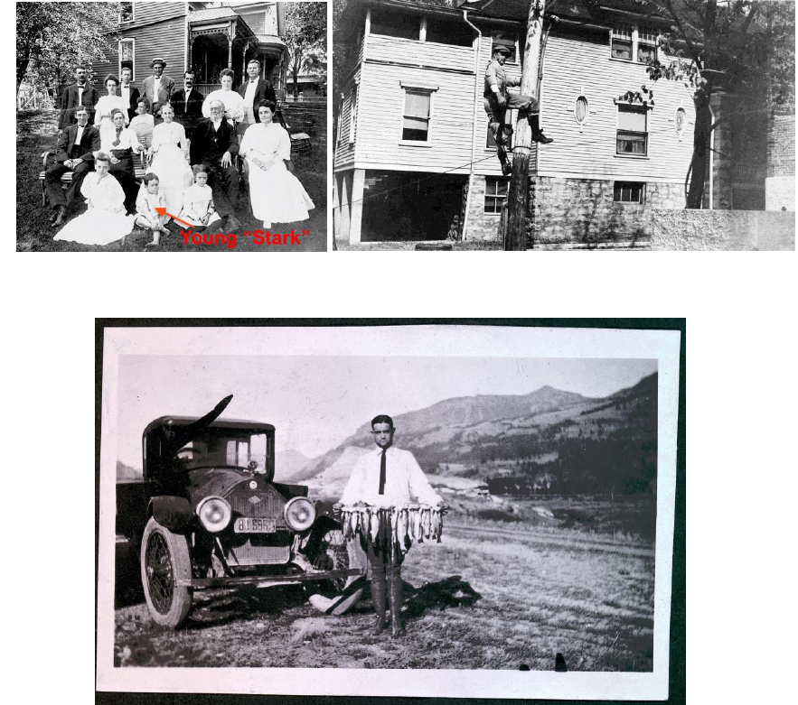
Charles Stark Draper was born in 1901 in Windsor Missouri. His father was a dentist and his
mother (nee Stark) was a school teacher. The Stark family developed the Stark apple that was
popular in the Midwest and raised the family to prominence
1
including a cousin, Lloyd Stark,
who became governor of Missouri in 1937. Draper was known to his family and friends as Stark
(Figure 1), and later in life was known by colleagues as Doc.
During his teenage years, Draper enjoyed tinkering with automobiles. He also worked as an
electric linesman (Figure 2), and at age 15 began a liberal arts education at the University of Mis-
souri in Rolla. After 2 years he transferred to Stanford University where he got a Psychology
degree om 1922.
1,2
While at Stanford he developed an interest in chemical and electrical instru-
ments upon observing their inaccuracies as used in the psychology lab.
3
After his graduation from Stanford, Draper drove with friends across the continent (through
Canada) to Boston (Figure 3). Upon their crossing the Charles River from Boston to Cambridge,
the new MIT campus attracted his attention. As his friends went on to see Harvard, Draper wan-
dered about MIT.
2
Upon seeing an electrochemical engineering course in a catalog in the MIT
admissions office, he asked if he could enter MIT. He was told there was a vacancy and given his
degree from Stanford, he could enter by paying a year’s tuition ($250) and a promise to spend the
next two summers working on mathematics courses he should have taken before applying. Short-
ly after he also registered as a student in the Army Air Corps Reserve Officers Training Corps.
4
*
Laboratory Technical Staff, Complexity Solutions Division, The Charles Stark Draper Laboratory, Inc., 555 Technol-
ogy Square, Cambridge, MA, 02139.
(Preprint) AAS 18-121
2
Figure 3. Draper During a Transcontinental Excursion by Car.
Draper spent the next four years earning a bachelor’s degree in electrochemical engineering,
receiving the degree in 1926. In parallel, he received a commission in the Army Air Corp as a
Second Lt., going to Brooks Field (San Antonio, TX) upon MIT graduation (Figure 4). Draper
washed out of the flight school four months into the six-month program. Overcoming his disap-
pointment, he took a job in New York working on an infrared signaling project for R.E. Gilmore
who had just resigned as President of Sperry Gyroscope to start a research and development lab
that included the Draper’s work. There Draper studied the use of infrared radiation for communi-
cations and locating targets. Though resources were very limited, Draper was able to construct a
primitive proof-of-concept demonstration device that suggested that infrared-sensitive receivers
could be developed into practical instruments. However, Navy funding for the project ended, and
Draper looked for a new job.
4
Figure 1. Draper as a Child.
Figure 2. Draper as a Teenage Electrical Wireman.

3
Figure 4. Draper in an Early Flight Simulator.
ORIGIN OF MIT’S INSTRUMENTATION LABORATORY
After his New York work ended, Draper returned to MIT (in 1928) as a Research Associate on
a fellowship sponsored by a General Motors grant to work on the spectroscopy of fuel flames in
the cylinders of internal combustion engines. That work was done in the Aeronautical Power
Plant Lab of the Aeronautical Engineering Department. While doing that work, Draper registered
for a Master’s Degree program that combined aeronautics, physics, and chemical engineering. In
1929 he also earned a civilian pilot’s license.
4
Draper’s combustion research morphed into a study of high frequency pressure variations dur-
ing combustion associated with “knocking.” This led the development of knock-indicator in-
struments under the sponsorship of Sperry Gyroscope, including a cylinder head-mounted accel-
erometer. In the same time frame, Prof. William Brown left MIT to work on blind instrument
flying experiments under the leadership of Jimmy Doolittle and the sponsorship of Harry Gug-
genheim. Brown had been teaching an Aircraft Instruments course at MIT, and it was left to
Draper (still then a Research Assistant) to take responsibility for teaching the course. Draper en-
thusiastically took on what he then called Informetics that he expanded from just sensing, pro-
cessing, and comparing information to newly include practical applications of control, navigation,
and guidance.
4
Julius Stratton, then a Professor at MIT and subsequently its President, observed
that he was never knew who was the instructor and who was the student in Draper’s class.
2
During the 1930s, Dr. Jerome Hunsaker and Professor Fay Taylor, convinced the Navy to pro-
vide a contract to measure the vibration in aeronautical engine crankshafts. Professor Taylor
conceived an undamped vibration absorber that could eliminate the crankshaft vibration problem,
and left Draper in charge of the associated instrument design problem. Draper worked with stu-
dents, to design, build, and flight test the resulting systems until the results were satisfactory to
the Navy (those systems became the MIT Sperry Vibration Measuring Equipment). Leveraging
off Draper’s knock-detection research, Taylor, Draper, and their laboratory team also developed
an engine analyzer that Sperry manufactured in large numbers for use on multi-engine, long-
4
range aircraft. These devices enabled aircrews to run aircraft engines as lean as possible, short of
knocking, maximizing aircraft range for any given takeoff fuel load.
2, 3,4
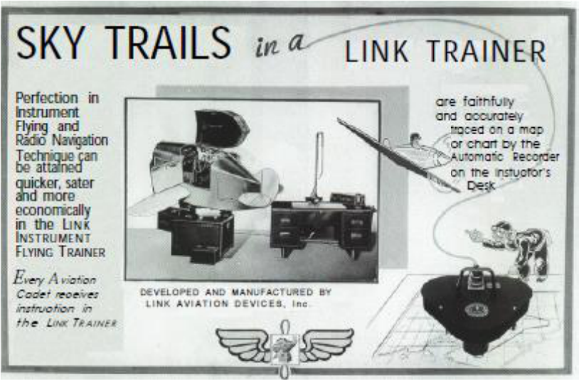
Many factors influenced the direction of Draper’s career in the 1930s. His aeronautical power
plant work led to much in-flight testing work, which facilitated and sustained his involvement in
development of theory for aircraft instruments and control. He spent time at the Boeing School
of Aeronautics in Oakland where he tried out the “Link Trainor” (Figure 5) that was a ground
simulator being used to train pilots for instrument flying. This spawned Draper’s interest in
needed improvements to aircraft bank and turn indicators that led to his work on gyro-based iner-
tial navigation technology.
3
Figure 5. Promotional Literature from the 1940s for the Link Trainer.
5
By the mid 1930’s Draper became an Associate Professor at MIT. In 1938 he got his PhD
from MIT in Physics, and by 1939 he was a Full Professor. Meanwhile, he, his faculty col-
leagues, and his students had built up what would become known as the MIT Instrumentation
Laboratory.
1,
2
APPLYING GYROSCOPES AS MOTION INSTRUMENTS
Draper’s early flying experiences had convinced him that better aircraft turn indication was
needed. In the early 1930s the state of the art was air-jet-driven, spring-restrained, single-degree-
of-freedom gyros carried by ball bearings. Draper realized that aircraft operational vibration
caused dents in the bearing races that could lead to erratic sensor readings. He believed that re-
placement of the ball bearing with spring suspensions and introduction of viscous damping could
mitigate those sensor problems. During summer employment by Sperry Gyroscope, he worked
with an aircraft instrument, mechanic, Harry Ashworth to develop and demonstrate spring-gimbal
suspended, and damped gyroscopic sensors (Figure 6). Flight testing of prototypes were success-
ful, stimulating pilot interest, but the on-going success of current Sperry instrument products di-

5
minished the company’s interest in marketing of an alternate instrument. However, the parallel
outbreak of World War II (WWII) indicated that targeting of guns against moving threats was
deficient. It was immediately apparent to Draper that gyroscopic instruments mounted to guns
mechanized to offset the gun aim point as a function of vehicle motion rates could greatly im-
prove the gun targeting accuracy. Discussions of this idea with Sperry representatives resulted in
some support as Draper returned to MIT to investigate use of his aircraft instrument design for
gun targeting improvement. Harry Ashworth went with Draper to MIT to build a gunsight for
engineering-level testing.
Figure 6. Draper’ Gimbal-Mounted, Viscous-Damped Single-Axis Gyro Sensor.
3
MAKING A BIG DIFFERENCE IN WORLD WAR II
Back at MIT in the fall of 1940, Draper leveraged his students (that included military officers)
to help with theory, design, and testing of gyroscopic gunsights.
3
In the design they needed to
compensate for the effects of sea state and the mechanical disturbances of rapid gun fire. Draper
chose to utilize elastically suspended gyro gimbals with adjustable spring restraints and viscous
damping that provided mechanical protection and output smoothing. Within one academic year,
the team had a prototype ready for testing that was about the size and shape of a shoebox. A ru-
dimentary test configuration was utilized that involved a towel with airplanes printed on it that
was attached to a movable clothesline set about 75 feet away from a .22 caliber rifle with the gun-
sight attached gun (Figure 7). The tests were performed at in a concrete-walled range at the Ar-
my’s Watertown Arsenal a few miles from MIT.
3
Because of its configuration, the gunsight took
on the nickname of Doc’s Shoebox” (Figure 8).
Initially there was no government or corporate interest in the new gunsight as in-production
systems were deemed sufficiently good. However, the British were already immersed in WWII

6
and British ships were not then being well protected by existing gun defenses. Sir Ralph Howard
Fowler, a British physicist and ballistics expert, visited MIT and was impressed upon trying out
the gunsight. He followed up by establishing contacts between the British Admiralty and Sperry
that resulted in the company designing and manufacturing several gunsights for the British.
4
In
parallel, the US Navy, on the advice of Naval officer students of Draper, took the gunsight to
Dahlgren Proving Ground and tested in on a 20mm machine gun against airplane-towed sleeve
targets. The excellent results of that test resulted in the government directing Sperry to produce
the gunsights under Draper supervision.
3
World events also accelerated the gunsight develop-
ment and deployment. On December 10, 1941, both the British Battleship Prince of Wales and
its Battlecruiser Repulse were lost due to Japanese air attack off the Malay peninsula, proving the
inefficacy of the then fielded ship defense gunsights against advancing aerial warfare capabili-
ties.
6
Figure 7. The Initial Test Arrangement for Draper’s Gimbaled, Target-Lead-Enabled Gunsight.
To expedite the gunsight readiness for field use, four rooms in the Aeronautics Department
building at MIT were utilized to further the preliminary design, and built a dozen field-able proto-
types that were successfully applied.
3
The resulting gunsight became known as the Mark 14. The
true efficacy of the Mark 14 gunsight was demonstrated on October 26, 1942. It “Made the fleet
relatively invulnerable to attack from aircraft…. In one engagement (it) enabled the battleship
South Dakota to shoot down 32 … planes.”
7
The Mark 14 “succeeded not because of the quality
or precision of its computation, but rather because of its compromises. Estimating range provided
the most significant shortcut. Rather than using a bulky and slow rangefinder, the operator mere-
ly estimated range by eye and then dialed it in by hand” (quote from Prof. David Mindell at
MIT).
8
About 100,000 Mark 14s were produced for use on a variety of platforms, including for
many Naval ship defense guns (Figure 9).
3

7
Figure 8. A Prototype Mark 14 (Doc’s Shoebox) Gunsight.
Figure 9. Draper Displaying a Naval Ship Defense Gun with an Integrated the Mark 14 Gunsight.

8
INERTIAL NAVIGATION FOR FLIGHT
By the late 1930s, Draper had graduate students pursuing “closed-box navigation solutions.”
Walter Wrigley’s 1941 doctoral dissertation done under Draper established the theoretical basis
for inertial navigation. This dissertation proposed using damped pendulous gyros as instruments
on a vehicle to determine the changes in inertial state of the vehicle (Figure 10).
9
By the end of
WWII, Draper and his team realized that improved gyroscopic instruments could provide “jam-
proof” systems that could automatically navigate both manned and unmanned vehicles, regardless
of weather, and without reliance on information from external sources.
10
In 1944, Draper and his
former graduate student Leighton Davis (who was then at the Wright Field Armament Laborato-
ry) began discussion of a self-contained inertial navigation system. This initially led to a 1945
contract to develop a self-contained aircraft bombing system with a target error not to exceed two
miles after ten hours of flight, but with an initial instantiation allowing solar and stellar observa-
tions to enable evaluation of the inertial system performance.
2,11
This led to development and
1949 B-29 test flights of the 4,000 lb navigation system FEBE (named for the Roman sun god
Phoebus) that used a star and magnetic coordinates as references. The FEBE test flights proved
that inertial navigation was then feasible over moderate distances without stellar tracking.
8
Figure 10. From the Doctoral Thesis of Walter Wrigley
9
– Illustration of How Torques Acting on a
Damped Pendulous Gyro Mounted on Gimbals Could be Used for Inertial Navigation.
In parallel to FEBE testing, Draper’s team began work on the Space Inertial Reference Equi-
ment (SPIRE).
8
SPIRE was a purely inertial system. It had three orthogonally mounted single
degree of freedom floated gyros for orientation data and three pendulous integrating gyro accel-
erometers, also orthogonally mounted on an inertial reference platform mounted within gimbals
to isolate the platform from carrier vehicle motion (Figure 11).
3
The “floating” placed a dense
Newtonian fluid (with viscosity independent of the shear rate) in a narrow gap between the gyros
cylinders and their container. By having a Newtonian fluid, the effect of shear on the gyro readi-
ly factored into sensor signal interpretation. Temperature control was necessary to keep the fluid
viscosity very close to the expected level.
2
An analog computer converted inertial coordinates to

9
earth-relative data. The overall system was designed to keep navigation errors to less than one
nmi after 10 hours of use in flight.
8
Figure 11. A Functional Diagram for the SPIRE Inertial Navigation System.
3
A SPIRE system, was placed on a B-29 for flight evaluation (Figures 12-13). It weighed
3,000 lb – all the design work had focused on successful function, not minimizing its size. A
one-hour shakedown flight was made on February 6, 1953. The next day it was used to navigate
the airplane on autopilot for the entire flight from Bedford, MA to Los Angeles. It performed to
specification, the results were documented that night, and they were presented the next day (Feb-
ruary 8) at a Symposium scheduled to discuss the possibility (now proven) of totally inertial
flight. With in-flight inertial navigation now proven realizable, all subsequent focus was to make
much smaller navigation systems that would meet specific mission needs.
8
Figure 13. Draper, Eric Sevareid, and
SPIRE on the B-29.
Figure 12. Spire During B-29
Installation.

10
GUIDANCE FOR SUBMARINE-LAUNCHED MISSILES
Draper and his team began to apply inertial sensing technology to marine vessel navigation in
1948 with the Marine Stable Element (MAST) program.
10
The program sought to determine the
vertical and azimuth with extreme precision using “specific force” sensors (Figure 14).
3
The first
sea trials were in March 1954. In parallel work began on the Submarine Inertial Navigation Sys-
tem (SINS) that had its first sea trials in November 1954.
10
These ship navigation systems estab-
lished a basis for providing a precision navigation initialization reference for missiles that could
be launched from the ships.
Figure 14. Draper’s Basis for a Single-Degree-of-Freedom Proof-Mass-Arm Specific Force Sensors.
3
In 1945 the Instrumentation Laboratory reported to the government that the possibility should
not be neglected that a stellar-aided inertial bombing system could eventually be robotized for use
with guided missiles. Draper and his team began work on the guided ballistic missile problem in
1953 in an arrangement with Consolidated Vultee Aircraft Corporation. Responsibility for that
work was soon taken by the Air Force. The work had progressed enough by 1955 to apply it to
the Thor Intermediate Range Ballistic Missile (IRBM). Resulting Instrumentation Laboratory
technology and subsystem designs were turned over to the AC Spark Plug Division of General
Motors to develop and manufacture the guidance system for Thor. The Thor successfully demon-
strated closed-loop inertial guidance in December 1957.
10
This arrangement for between the In-
strumentation Laboratory and AC Spark Plug for the Thor guidance system became a model for a
guidance system government design agent role that the Instrumentation Laboratory would often
subsequently follow.
While the Thor was nearing completion, Draper and his Instrumentation Laboratory Team
were asked to design the guidance system for the submarine-launched Polaris IRBM.
10
The re-
sulting inertial space-referenced MK1 guidance system (akin that that shown in Figure 15) came
in at 225 pounds using printed circuit boards and a digital computer , with a Circular Error Proba-

11
ble (CEP) of about 2 nmi over the Polaris flight range.
8
The first fully inertial MK1 Polaris mis-
sile launch from a submerged submarine was on July 20, 1960 (Figure 16).
10
Figure 15. A Functional Representation of Draper’s Inertial Navigation System with an Inertial
Space Reference Earth Coordinate Indicating Subsystem
3
.
Figure 16. A Submarine-Launched Polaris with an Instrumentation Laboratory Inertial Guidance
System.

12
The submarine ballistic missile guidance capabilities continued to advance. A MK2 version
first launched on a longer-range Polaris in February 1962
10
weighing under 140 lb, and with a
CEP of about 0.5 nmi.
8
After that, the Instrumentation Laboratory and its successor Charles Stark
Draper Laboratory served as government design agents for the entire sequence of progressively
more capable and precise Navy submarine-launched Intercontinental Ballistic Missile (ICBM)
guidance systems (that included Poseidon, Trident I and Trident II). Applicable guidance system
capabilities were also applied to a number of Air Force ICBM programs (e.g., Titan and Peace-
keeper).
A KEY ROLE IN APOLLO
Soon after President Kennedy announced the goals for the Apollo program, Draper and Milt
Tragesor, also from the Instrumentation Laboratory, had a meeting with NASA Administrator
James Webb as well as Deputy Administrator Hugh Dryden and Associate Administrator Robert
Seamans (another former Draper student). At that meeting Draper told the NASA leadership that
the Instrumentation Laboratory had the means to conceive, work out theory for design, and over-
see the construction of guidance and control systems for Apollo vehicles, as well as the ability to
consult during use of those systems.
11
What Draper was proposing to the NASA Leadership
would leverage work done in the late 1950s for the Air Force under the leadership of Milton
Tragesor that addressed fully integrated, deep-space capable Guidance Navigation and Control
(GN&C) technology, including required computing capabilities, to enable an unmanned Mars
vehicle (Figure 17). That study for the Air Force was reported in five volumes in 1959 address-
ing a mission from Earth to Mars and back, with the vehicle imaging Mars at close range during a
fly-by on film, with the vehicle and film then returning to Earth. Richard Battin and J. Halcombe
Laning were also key contributors to the study (Figure 18), with Battin addressing interplanetary
trajectories and guidance, while Laning, with Tragesor addressing use of a central computer that
would enable execution of alternative courses of action as needed (in addition to its routine man-
agement of spacecraft functions).
12
Very soon thereafter, NASA issued the first Apollo contract
to the Instrumentation Laboratory, with Sen. Leverett Saltonstall notifying the Laboratory of that
selection by telegram on August 9, 1961.
8
Key leaders from the Polaris program work (e.g., Da-
vid Hoag) would be utilized to apply their hard-learned system design and development expertise
to Apollo. Draper’s consultations with top NASA and US government leadership about Apollo
and other program plans/status were on-going events (see Figures 19-20).
Figure 17. A Mars Mission Vehicle Concept Used as an Apollo Model.

13
Development of a volume and power-limited computer and its software for management and
control of all Apollo mission events was the most critical technology for achieving the goals of
the program.
8
Getting the digital capacity into the allocated volume of 1 ft
3
necessitated clever
memory design. The final computer design had 36,000 words of woven rope core memory that
had its programing implementation frozen upon fabrication. It also had 2,000 words of Random
Access Memory (RAM). If the RAM had relied on the transistors in prevalent use at the time,
then the computer volume and power constraints could not have been met. Fortunately, at the
time, Integrated Circuit (IC) technology was being developed. The state-of-the-art at that time
would allow the equivalent of several transistors to be included on each IC chip. The Instrumen-
tation Laboratory chose the IC technology, enabling a 12 microsecond clock speed. In 1963 the
Instrumentation Laboratory consumed 60% of the US IC production for Apollo use, receiving
Figure 20. Apollo Discussion Aboard Air Force One with (left to right) Frederick
Seitz, James Webb, Draper, and President Johnson. Seitz, a Solid State Physicist
was then President of the National Academy of Sciences.
Figure 18. (left to right) J. Halcombe Laning,
Milton Trageser, and Richard Battin with a
Model of the Proposed Mars Mission Space-
craft.
Figure 19. Draper with Wernher von Braun.

14
more than 100,000 ICs by 1964
13
Also needed for the computer were processing-efficient GN&C
algorithms, a compiler, and electronics design/integration expertise. Applicable design leadership
in these disciplines was provided by Instrumentation Laboratory employees Richard Battin, J.
Halcombe Laning, and Eldon Hall respectively. The Guidance system hardware was evolved
from the Polaris system design, but with the addition of a stellar alignment capability that could
compare crew optical sightings with computer gimbal angle readings from the inertial navigation
system. That added optical update capability was a backup to ground-based ranging tracking up-
dates in the event that the flight vehicle lost communi8caitons with the ground. A sextant was
built into the installed Apollo vehicle guidance system for this purpose (Figure 21).
Figure 21. Schematic of the Apollo Guidance and Processing System.
3
(Computer Specifications are
from Ref. 12.)
CHANGED DRAPER ROLE WITH THE BIRTH OF THE CHARLES STARK DRAPER
LABORATORY
As the Instrumentation Laboratory grew, it occupied a variety of widely distributed buildings
in Cambridge, MA. Much of its work related to strategic military systems. During the era of the
Vietnam war, there was significant risk that, because of student pressure, the MIT leadership
would restrict the scope of the Laboratory’s work. That resulted in an amicable separation of the
Laboratory from MIT in 1973, creating the Charles Stark Draper Laboratory, Inc. as a new, inde-
pendent, not-for-profit institution with the objectives of developing technology in the national
interest, and supporting advanced education of students in disciplines with ties to the corpora-

15
tion’s research and development work. An important initial focus of the new organization was its
financial survival as an independent institution. That resulted in a new management structure that
placed Doc Draper in the position of Senior Scientist, and Robert Duffy as the President and
Chief Executive Officer. Soon after its creation, the corporation began construction of a new
home in Technology Square in Cambridge (very close to MIT) that consolidated its work force
into one location. Doc Draper adapted to his new role by applying his accumulated expertise to
addressing global policy issues (e.g., interacting with the White House regarding proposed Stra-
tegic Arms Limitation Treaties
14
), addressing student interests, and making presentations that ad-
dressed some of the history of the many amazing developments that his vision, invention, and
design had enabled. Draper continued in these roles until he passed away in 1987. I was a
Draper Fellow during that period, a graduate student at MIT doing my MIT Research Assis-
tantship on projects at the Charles Stark Draper Laboratory. Draper was generous with his time
with students, participating in many events with them, and providing career inspiration. I was
privileged to have the opportunity during those years to interact with Doc Draper on a number of
occasions.
HONORING DOC IN PERPETUITY: THE DRAPER PRIZE FOR ENGINEERING
The Nobel prizes provide a world stage for major scientific contributions, but there is no No-
bel prize for engineering achievements. To mitigate that shortfall, the Charles Stark Draper Prize
for Engineering was established, commemorating Draper’s globally impactful engineering contri-
butions by recognizing engineering achievements with major global impact by others of any na-
tionality. The prize was established by the National Academy of Science at the request of the
Charles Stark Draper, Laboratory, Inc.,
15
and is a preeminent global prize in that category. An
aim of the prize is to improve public understanding of the importance of engineering and technol-
ogy. It was first awarded in 1989, initially as a bi-annual award, but now is awarded annually,
with winners responsible for a wide range of engineering contributions. The prize is $500,000
and a medal (Figure 22). Those who knew Draper well think he would have been thrilled to have
been a recipient of such a prize.
Figure 22. The Medallion Presented to Winners of the Draper Prize for Engineering.
CONCLUSION
Doc Draper was responsible for conceiving and leading the development of practical, reliable,
and precise inertial guidance system technology. Starting from Missouri roots he pursued educa-
tion in psychology, electrochemical engineering, and physics, all of which contributed to his suc-
16
cess as an inventor and as an influencer of the national leadership that provided the resources to
field the resulting technology. He also attracted students and staff with remarkable talents that
leveraged and greatly expanded on Draper’s concepts, enabling incredible engineering advances
in aerospace guidance, navigation, and control over just a few decades. That technology and re-
sulting systems helped turn the tide of the WWII battles in the Pacific in favor of the United
States, enabled modern strategic defense systems, and was critical to the success of the Apollo
program. In many ways, Draper rightfully earned the title of Father of Inertial Guidance. For
that, he was widely recognized during his life for the those achievements (see the Appendix).
ACKNOWLEDGMENTS
The material presented in this paper and its interpretation is the responsibility of the author
alone. However, it also must be noted that Ingrid (Drew) Crete was invaluable as a source of all
raw material about Doc Draper used in the paper. She helped to systematically sift through many
documents and artifacts from Doc’s archives at the Charles Stark Draper Laboratory and to find
relevant historical photographs. Her contributions were essential to timely completion of this
presentation of Doc Draper’s history.
Note that any figures not explicitly tagged as coming from a reference were acquired from the
archives of the Charles Stark Draper Laboratory, Inc.
APPENDIX: SOME OF DRAPER’S ACCOLADES
10
1946 Medal of Merit, Naval Ordnance Development Award
Sylvanus Albert Reed Award, Institute of the Aeronautical Sciences
1947 New England Award of the Engineering Societies of New England
1951 Exceptional Civilian Service Award of the Department of the Air Force
1955 43
rd
Wilbur Wright Memorial Lectureship of the Royal Aeronautical Society
1957 Navy Distinguished Public Service Award
Thurlow Award, the Institute of Navigation
Holley Medal, American Society of Mechanical Engineers
1958 Honorary Fellowship, Institute of the Aeronautical Sciences
Blandy Medal, American Ordnance Association
1959 William Proctor Prize of the Scientific Research Society of America
1960 U.S. Air Force Exceptional Service Award
Potts Medal of the Franklin Institute
1961 Navy Distinguished Public Service Award
1962 Space Flight Award, American Astronautical Society
Louis W. Hill Space Transportation Award, American Institute of Aeronautics and
Astronautics
1964 The Commander’s Award, Ballistic Systems Division, US Air Force
1965 National Medal of Science, a Presidential Award
1966 Wright Brothers Lecture, American Institute of Aeronautics and Astronautics
Vincent Bendix Award, American Society for Engineering Education
1967 Daniel Guggenheim Award
Distinguished Public Service Award, NASA
1968 Exceptional Civilian Service Award, US Air Force

17
1969 Public Service Award, NASA
Exceptional Civilian Service Award, U.S. Air Force
1970 Founders Medal, National Academy of Engineering
Distinguished Civilian Service Medal, Department of Defense
1971 W. Randolph Lovelace, II Award, American Astronautical Society
Rufus Oldenburger Award, American Society of Mechanical Engineers
1972 Lamme Medal Award, Institute of Electrical and Electronics Engineers
1974 Kelvin Gold Medal Award, Institution of Civil Engineers, London, England
1976 Inducted into the International Space Hall of Fame
1977 Allan D. Emil Memorial Award of the International Astronautical Federation
1978 Dr. Robert H. Goddard Trophy, National Space Club
Pioneer Award, Institute of Electrical and Electronics Engineers
1979 Inducted into the French Academy of Sciences
1980 Eagle Award for the Advancement of Astronautics, American Astronautical Society
1981 Elected into the National Inventors Hall of Fame
Langley Medal, Smithsonian Institution
Control Heritage Award, American Automatic Control Council
Enshrined in the Aviation Hall of Fame
REFERENCES
1
Louis L. Junod, “Charles Stark Draper, a Biographical Essay about Personality Development,” 1983, College of Wil-
liam and Mary.
2
Robert A. Duffy, “Charles Stark Draper, October 2, 1901 – July 25, 1987,” Charles Stark Draper Laboratory paper
CSDL-91-041.
3
Charles Stark Draper, ““Aircraft and Spacecraft Navigation,” The Seventeenth Lester D. Gardner Lecture, MIT, Oc-
tober 1978.
4
Charles Stark Draper, “On Course to Modern Guidance,” Aeronautics and Astronautics, February 1980.
5
“The Link Flight Trainer, A Historic Mechanical Engineering Landmark,” an ASME International publication, June
10, 2000.
6
Charles Stark Draper, a 1946 booklet.
7
The Stars and Stripes, April 10, 1945.
8
Draper Laboratory, 40 Years as an Independent R&D Institution, 80 Years of Outstanding Innovations and Service to
the Nation, 2013.
9
Walter Wrigley, “An Investigation of Methods Available for Indicating the Direction of the Vertical from a Moving
Base,” MIT Doctoral Dissertation, 1941.
10
“Biographical sketch of Dr. Charles Stark Draper,” May 1983.
11
Charles Stark Draper, Transcript of Remarks to the International Space Hall of Fame, September 8, 1977.
12
David A. Mindell, Digital Apollo: Human and Machine in Spaceflight, MIT Press, 2011.
13
Jon Tylko, “MIT and navigating the path to the moon,” highlight from the MIT 2008-2009 AeroAstro Magazine, at:
http://web.mit.edu/aeroastro/news/magazine/aeroastro6/mit-apollo.html.
14
Frank Press, the Science and Technology Advisor to the President in official White House correspondence with
Charles Stark Draper providing information about terms and plans for a proposed Strategic Arms Limitation Treaty,
May 16, 1979.

