
Welch Allyn Connex
®
Vital Signs Monitor
6000 Series™
Service manual
Software versions 2.0X – 2.4X

© 2023 Welch Allyn. All rights are reserved. The purchaser is permitted to copy this publication, for internal
distribution only, from the media provided by Welch Allyn. No other use, reproduction, or distribution of this
publication, or any part of it, is permitted without written permission from Welch Allyn.
Legal Statement. Welch Allyn, Inc. (“Welch Allyn”) assumes no responsibility for any injury to anyone that may result
from (i) failure to properly use the product in accordance with the instructions, cautions, warnings, or statement of
intended use published in this manual, or (ii) any illegal or improper use of the product.
Welch Allyn, Connex, SureTemp, and SureBP are registered trademarks of Welch Allyn.
Integrated Pulmonary Index, Oridion, and Microstream are trademarks of a Medtronic company. No implied license.
Possession or purchase of this device does not convey any express or implied license to use the device with
unauthorized CO2 sampling products which would, alone, or in combination with this device, fall within the scope of
one or more of the patents relating to this device and/or CO2 sampling products.
Radical-7R, Pulse CO-Oximeter, rainbow Acoustic Monitoring, RRa, and ReSposable are trademarks of, and SET, LNCS,
SpHb, rainbow, and Masimo are registered trademarks of Masimo Corporation. Possession or purchase of a Masimo-
equipped device does not convey any express or implied license to use the device with unauthorized sensors or
cables which would, alone or in combination with this device, fall within the scope of one or more of the patents
relating to this device. For Masimo patent information, please visit www.masimo.com/patents.htm.
Nellcor SpO2 Patient Monitoring System with OxiMax Technology and Nellcor SpO2 OxiMax Technology are
trademarks of a Medtronic company. For Nellcor patent information, please visit https://www.masimo.com/
company/masimo/patents/.
Braun and ThermoScan are registered trademarks of Braun GmbH.
Nonin is a registered trademark of Nonin Medical, Inc.
Bluetooth is a registered trademark of Bluetooth SIG.
Welch Allyn has provided Clinical Dynamics of CT, LLC, the calibration tables (CALTables) for use in its AccuPulse and
AccuSim NIBP Simulators. For more information, visit https://www.clinicaldynamics.com/contact.
Software in this product is Copyright 2023 Welch Allyn or its vendors. All rights are reserved. The software is protected
by United States of America copyright laws and international treaty provisions applicable worldwide. Under such
laws, the licensee is entitled to use the copy of the software incorporated with this instrument as intended in the
operation of the product in which it is embedded. The software may not be copied, decompiled, reverse-engineered,
disassembled, or otherwise reduced to human-perceivable form. This is not a sale of the software or any copy of the
software; all right, title, and ownership of the software remain with Welch Allyn or its vendors.
This product may contain software known as “free” or “open source” software (FOSS). Hill-Rom uses and supports the
use of FOSS. We believe that FOSS makes our products more robust and secure, and gives us and our customers
greater flexibility. To learn more about FOSS that may be used in this product, please visit our FOSS website at
hillrom.com/opensource. Where required, a copy of FOSS source code is available on our FOSS website.
PATENTS / PATENT hillrom.com/patents.
May be covered by one or more patents. See above Internet address. The Hill-Rom companies are the proprietors of
European, US, and other patents and pending patent applications.
For information about any product, contact Hillrom Technical Support: hillrom.com/en-us/about-us/locations/.
80026025 Ver. B Revision date: 2023-01
Welch Allyn, Inc.
4341 State Street Road
Skaneateles Falls, NY 13153 USA
Welch Allyn, Inc. is a subsidiary of Hill-Rom Holdings, Inc.
hillrom.com

Contents
Symbols ......................................................................................................................................... 1
Safety .............................................................................................................................................. 5
Warnings and cautions ..................................................................................................................................................... 5
General safety considerations ...................................................................................................................................... 6
Electrostatic discharge (ESD) ........................................................................................................................................ 6
Overview ....................................................................................................................................... 9
Purpose and scope ............................................................................................................................................................. 9
Technical support services .......................................................................................................................................... 10
Recommended service intervals ............................................................................................................................. 14
The Welch Allyn Service Tool ..................................................................................................................................... 15
Battery performance ....................................................................................................................................................... 17
Controls, indicators, and connectors ................................................................................ 19
Advanced settings ................................................................................................................... 23
General ..................................................................................................................................................................................... 23
Parameters ............................................................................................................................................................................. 29
Data management ........................................................................................................................................................... 38
Network ................................................................................................................................................................................... 42
Service ...................................................................................................................................................................................... 48
Power-up sequence ................................................................................................................ 55
Troubleshooting ...................................................................................................................... 57
Symptoms and solutions ............................................................................................................................................. 57
Technical alarm messages ........................................................................................................................................... 71
Disassembly and repair ......................................................................................................... 89
Required tools and equipment ................................................................................................................................ 92
Disassembly overview .................................................................................................................................................... 93
Section A ..................................................................................................................................... 95
Power down the device ................................................................................................................................................ 95
Remove the battery ......................................................................................................................................................... 96
Remove the rear housing ............................................................................................................................................ 97
Remove the communications door ...................................................................................................................... 99
Disassemble the rear housing ................................................................................................................................ 102
Disassemble the main chassis ................................................................................................................................ 111
Disassemble the front housing .............................................................................................................................. 138
iii
Section B ................................................................................................................................... 153
Power down the device ............................................................................................................................................. 154
Remove the battery ...................................................................................................................................................... 155
Remove the rear housing .......................................................................................................................................... 156
Remove the communications door ................................................................................................................... 159
Disassemble the rear housing ................................................................................................................................ 162
Disassemble the main chassis ................................................................................................................................ 172
Disassemble the front housing .............................................................................................................................. 199
Functional verification and calibration ......................................................................... 213
Functional verification tests ..................................................................................................................................... 213
Basic functional verification checks .................................................................................................................... 218
Electrical safety testing ....................................................................................................... 235
Ground stud connector .............................................................................................................................................. 236
Options, upgrades, and licenses ...................................................................................... 237
Available options, upgrades, and licenses ...................................................................................................... 238
Install options ................................................................................................................................................................... 242
Host firmware requirements ................................................................................................................................... 245
Masimo parameter upgrades ................................................................................................................................. 245
Configure options .......................................................................................................................................................... 246
Chinese fonts and input method editor (IME) tables .............................................................................. 246
Field replaceable units ........................................................................................................ 249
Table for service kits ...................................................................................................................................................... 249
Licenses ................................................................................................................................................................................ 255
SmartCare services for maintenance and repair ......................................................................................... 256
Service and repair training ........................................................................................................................................ 257
Service tools ....................................................................................................................................................................... 258
Appendix .................................................................................................................................. 259
Decontamination and cleaning requirements for returns ................................................................... 259
Identifying the monitor and subsystems ........................................................................................................ 262
Factory defaults ............................................................................................................................................................... 265
Disassembly and repair reference ........................................................................................................................ 286
Interconnect diagram .................................................................................................................................................. 295
Service and maintenance toolset ........................................................................................................................ 298
Connex Direct ......................................................................................................................... 303
Introduction ....................................................................................................................................................................... 303
Active Directory setup ................................................................................................................................................. 307
Project workflow ............................................................................................................................................................. 331
Troubleshooting ............................................................................................................................................................. 332
Service record ......................................................................................................................... 339
iv Contents

Symbols
For information on the origin of these symbols, see the Welch Allyn symbols glossary: https://
www.hillrom.com/content/dam/hillrom-aem/us/en/sap-documents/LIT/80022/
80022945LITPDF.pdf.
Documentation symbols
WARNING The warning statements in this manual identify conditions or practices
that could lead to illness, injury, or death.
CAUTION The caution statements in this manual identify conditions or practices that
could result in damage to the equipment or other property, or loss of data.
WARNING Hot surface. Do not touch.
Follow the operating instructions for use (IFU) — mandatory action.
A copy of the IFU is available on this website.
A printed copy of the IFU can be ordered from Hillrom for delivery within 7 days.
Power symbols
Power on/Display power-saving
[recent models]
Equipotential terminal
Power on/Display power-saving
[older models]
1

(on the display) monitor is
plugged into Alternating
Current power
Battery absent or faulty
(on the monitor, green
indicator) Alternating Current
power present, battery fully
charged
Battery charge level
(on the monitor, amber
indicator) Alternating Current
power present, battery is
charging
Battery cover
Alternating Current (AC) Rechargeable battery
Li-ion battery AC input power
Connectivity symbols
USB Ethernet RJ-45
Wireless signal strength
• Best (4 bars)
• Good (3 bars)
• Fair (2 bars)
• Weak (1 bar)
• No signal (no bars)
• No connection (blank)
Nurse call
[recent models]
Nurse call
[older models]
Connected to central station Disconnected from central
station
Miscellaneous symbols
CO2 sampling input CO2 sampling output/exhaust
Manufacturer Limited rotation/Turn
completely to right
2 Symbols

Reorder number Serial number
Do not reuse China RoHS markings for
control of pollution caused by
electronic information products.
XX indicates Environmentally
Friendly Use Period in years.
Nonionizing electromagnetic
radiation
Recycle the product separate
from other disposables
Restrictions for use of wireless
device in Europe. European
Community's Class 2 radio
equipment.
Call for maintenance
Defibrillation-proof Type BF
applied parts
Defibrillation-proof Type CF
applied parts
Atmospheric pressure limitation Not for injection
Transport and storage
temperature range
Authorized Representative of
the European Community
Recycle IPX2
(Vital Signs
Monitor)
IP = International Protection
Marking
X = No object ingress rating
2 = Protected against vertically
falling water drops when
enclosure tilted up to 15°
IPX0
(Integrated
Wall System)
Degree of protection provided
by the enclosure with respect
to harmful ingress of liquids
Do not expose to open flame Product Identifier
Stacking limit by number Keep dry
Service manual Symbols 3

Mobile stand symbols
Maximum safe working load
limits
(specific values presented with
symbol)
Mass in kilograms (kg)
CAUTION The caution statements in this manual identify conditions or practices that could
result in damage to the equipment or other property, or loss of data.
4 Symbols

Safety
All users of the monitor must read and understand all safety information presented in this manual
before using or repairing the monitor.
United States federal law restricts this device to sale, distribution, or use by or on the order of a
licensed medical practitioner.
Warnings and cautions
WARNING Safety risk. Make frequent electrical and visual checks on cables,
sensors, and electrode wires. All cables, sensors, and electrode wires must be
inspected and properly maintained and in proper working order to allow the
equipment to function properly and to protect patients.
WARNING Safety risk. Place the system and accessories in locations where they
cannot harm the patient should they fall from a shelf or mount.
WARNING Fire and explosion hazard. Do not operate the system in the presence
of a flammable anesthetic mixture with air, oxygen, or nitrous oxide; in oxygen-
enriched environments; or in any other potentially explosive environment.
WARNING Inaccurate measurement risk. Dust and particle ingress can affect the
accuracy of blood pressure measurements. Use the system in clean environments
to ensure measurement accuracy. If you notice dust or lint build-up on the
system’s vent openings, have the system inspected and cleaned by a qualified
service technician.
WARNING Defective batteries can damage the device. If the battery shows any
signs of damage or cracking, replace it immediately, and only with a battery
approved by Welch Allyn.
CAUTION Before disassembling the device or installing options, disconnect the
patient from the system, power down the device, and disconnect the AC power
and any attached accessories (for example, SpO2 sensors, blood pressure hoses
and cuffs, and temperature probes) from the device.
CAUTION To ensure that the system meets its performance specifications, store
and use the system in an environment that maintains the specified temperature
and humidity ranges.
5

CAUTION The system may not function properly if dropped or damaged. Protect
it from severe impact and shock. Do not use the system if you notice any signs of
damage.
CAUTION Do not connect more than one patient to a system or connect more
than one system to a patient.
CAUTION Do not operate the system in the presence of magnetic resonance
imaging (MRI) or hyperbaric chambers.
CAUTION Do not autoclave the system. Autoclave accessories only if the
manufacturer’s instructions clearly approve it.
CAUTION Do not exceed the maximum weight limits for your mobile stand with
basket or bins. See the "Specifications" section of the device’s Instructions for use for
the basket/bin and mobile stand maximum weight limits.
General safety considerations
• If the monitor detects an unrecoverable problem, it displays an error message. For more
information see “Troubleshooting.”
• To ensure patient safety, use only accessories recommended or supplied by Welch Allyn. (See
the accessories list in the user documentation or https://parts.hillrom.com/hillromUS/en/.)
Always use accessories according to your facility’s standards and according to the
manufacturer’s recommendations and instructions. Always follow the manufacturer’s
instructions for use.
• Welch Allyn recommends that only Welch Allyn service personnel or an authorized repair
center perform warranty service. Performing unauthorized service on a device that is within
warranty may void the warranty.
Electrostatic discharge (ESD)
CAUTION Electrostatic discharge (ESD) can damage or destroy electronic
components. Handle static-sensitive components only at static-safe workstation.
CAUTION Assume that all electrical and electronic components of the monitor
are static-sensitive.
Electrostatic discharge is a sudden current flowing from a charged object to another object or to
ground. Electrostatic charges can accumulate on common items such as foam drinking cups,
cellophane tape, synthetic clothing, untreated foam packaging material, and untreated plastic bags
and work folders, to name only a few.
Electronic components and assemblies, if not properly protected against ESD, can be permanently
damaged or destroyed when near or in contact with electrostatically charged objects. When you
6 Safety
handle components or assemblies that are not in protective bags and you are not sure whether
they are static-sensitive, assume that they are static-sensitive and handle them accordingly.
• Perform all service procedures in a static-protected environment. Always use techniques and
equipment designed to protect personnel and equipment from electrostatic discharge.
• Remove static-sensitive components and assemblies from their static-shielding bags only at
static-safe workstations—a properly grounded table and grounded floor mat—and only when
you are wearing a grounded wrist strap (with a resistor of at least 1 megohm in series) or other
grounding device.
• Use only grounded tools when inserting, adjusting, or removing static-sensitive components
and assemblies.
• Remove or insert static-sensitive components and assemblies only with monitor power turned
off.
• Insert and seal static-sensitive components and assemblies into their original static-shielding
bags before removing them from static-protected areas.
• Always test your ground strap, bench mat, conductive work surface, and ground cord before
removing components and assemblies from their protective bags and before beginning any
disassembly or assembly procedures.
Service manual Safety 7
8 Safety

Overview
Purpose and scope
This manual is a reference for periodic preventive maintenance and corrective service procedures
for the Welch Allyn Connex Vital Signs Monitor 6000 Series, firmware versions 2.0X–2.4X. It is
intended for use only by trained and qualified service personnel.
This manual is a reference for periodic preventive maintenance and corrective service procedures
for the Welch Allyn Connex Integrated Wall System, firmware version 2.3X-2.4X. It is intended for
use only by trained and qualified service personnel.
Corrective service is supported to the level of field-replaceable units. These include circuit-board
assemblies and some subassemblies, case parts, and other parts.
CAUTION No component-level repair of circuit boards and subassemblies is
supported. Use only the repair procedures described in this manual.
WARNING When performing a service procedure, follow the instructions exactly
as presented in this manual. Failure to do so could damage the device, invalidate
the product warranty, and cause serious personal injury.
Find instructions for functional testing and performance verification in the Welch Allyn Service Tool
help files.
This manual applies only to this device. For servicing of any other device, see the service manual for
the specific device.
Service work not described in this manual must be performed by qualified service personnel at the
factory or at an authorized Welch Allyn service center.
Related documents
When using this manual, refer to the following:
• Welch Allyn Connex® Devices Instructions for use, Software version 2.4X
• Welch Allyn Service Tool
https://www.hillrom.com/en/services/welch-allyn-service-tool/
• Welch Allyn Service Tool Installation and configuration guide
https://www.hillrom.com/en/services/welch-allyn-service-tool/
• Welch Allyn Braun ThermoScan® PRO 6000 Ear Thermometer, Service manual
click here to download the PDF
• Welch Allyn 9600 Plus Calibration Tester Directions for use click here to download the PDF
9

• Hillrom website: hillrom.com
Technical support services
Welch Allyn offers the following technical support services:
• Telephone support
• Loaner equipment
• Service agreements
• Service training
• Replacement service parts
• Product service
For information on any of these services, contact Hillrom Technical Support: hillrom.com/en-us/
about-us/locations/.
Service loaners
For warranty or non-warranty repairs not covered under a support agreement, loaners are available
for a nominal charge, subject to availability. Payment is required prior to shipment for all loaners
not covered under a support agreement.
Welch Allyn Service Centers that provide repair service for this product can, on request, loan a
device for use while the device is being repaired. Loaned devices are provided free of charge for
products repaired while under a support agreement that includes a free loaner provision.
Loaner equipment for the individual component modules is not available.
Service options
SmartCare™ services for maintenance and repair
While product warranties provide basic assurance of Welch Allyn hardware quality, they may not
include the full range of services and support you need. Welch Allyn offers premium service and
support through our SmartCare program. Whether you service your own devices and require a
minimum of support or rely on us to service your device, Welch Allyn provides a program that will
meet your needs. A list of available service and support agreements is presented in the "Field
replaceable units" section of this manual.
For more information, call your sales representative or visit our website:
https://www.hillrom.com/en/services/.
SmartCare Remote Management
SmartCare Remote Management is a secure cloud-based portal that offers biomeds access to
manage their Hillrom connected devices remotely in a centralized portal.
For more Information and a complete list of compatibility information, refer to the SmartCare
Remote Management Instructions for use.
10 Overview

Warranty service
All repairs on products under warranty must be performed or approved by Welch Allyn. Refer all
warranty service to Welch Allyn Product Service or another authorized Welch Allyn Service Center.
Obtain a Return Material Authorization (RMA) number for all returns to Welch Allyn Product Service
from our website:
http://www.welchallyn.com/en/service-support/submit-a-repair.html.
CAUTION Unauthorized repairs will void the product warranty.
Non-warranty service
Welch Allyn product service and authorized service centers support non-warranty repairs. Contact
any Welch Allyn regional service center for pricing and service options.
Welch Allyn offers modular repair parts for sale to support non-warranty service. This service must
be performed only by qualified end-user biomedical/clinical engineers using this service manual.
Service training is available from Welch Allyn for biomedical/clinical engineers. Follow this link for
more information.
Repairs
A Welch Allyn Service Center must perform all repairs on products under warranty, unless you have
purchased a Welch Allyn Partners in Care Biomed agreement allowing you to service the device
while under warranty.
CAUTION Unauthorized repairs will void the product warranty.
Qualified service personnel or a Welch Allyn Service Center should repair products out of warranty.
If you are advised to return a product to Welch Allyn for repair or routine maintenance, schedule
the repair with the service center nearest you.
Welch Allyn Technical Support
If you have a problem with the device that you cannot resolve, call the Welch Allyn Technical
Support Center nearest you for assistance. A representative will assist you in troubleshooting the
problem and will make every effort to solve the problem over the phone, potentially avoiding an
unnecessary return.
To expedite response to your issue, be prepared to provide details on how (steps executed) and
when (time and date) the problem occurred. Also, log and configuration files captured on the
device can assist with diagnosis and troubleshooting. You can easily save these files from the
device to a flash drive using controls on the Service tab. See the "Service menu" section of this
manual for details.
If your product requires warranty, extended warranty, or non-warranty repair service, a Welch Allyn
Technical Support representative will record all necessary information to issue an RMA number. The
support representative will provide you with the address of the Welch Allyn Service Center to send
your device to.
Technical support is available during local business hours.
Service manual Overview 11

Returning products
When returning a product to Welch Allyn for service, ensure that you have the following
information:
• Product name, model number, and serial number. This information may be found on the
product and serial number labels on the bottom of the device.
• A complete return shipping address.
• A contact name and phone number.
• Any special shipping instructions.
• A purchase order number or credit card number if the product is not covered by a warranty.
• A SmartCare contract number if product is covered under a service agreement.
• A full description of the problem or service request.
1. Obtain an RMA number:
• Visit us on the web at https://www.welchallyn.com/en/service-support/submit-a-repair/,
or
• Contact Welch Allyn to make a request.
NOTE Welch Allyn does not accept returned products without an
RMA.
2. Ship the device to Welch Allyn, observing these rules:
12 Overview

a. Remove from the package the battery, all hoses, connectors, cables, sensors, power cords,
and other ancillary products and equipment, except those items that might be associated
with the problem.
b. Follow shipping and handling requirements regarding Lithium-ion batteries to comply
with new IATA regulations.
Requirements for returning Lithium-ion batteries
• Remove the Lithium-ion battery from the device. You cannot ship these devices with
batteries installed.
• Follow packaging requirements (presented next in this section).
• Do not ship any battery that has been physically damaged or shows signs of leakage.
• Do not ship any battery that has been recalled by the supplier or manufacturer.
• Do not ship any waste batteries that should be recycled or discarded.
• Do not ship multiple batteries together.
• Use ground transportation only to ship Lithium-ion batteries.
Packaging requirements for Lithium-ion batteries and associated devices
• Use packaging provided by Welch Allyn or the battery manufacturer to pack the
battery. Seal the battery in the anti-static bag and place it in the shipping box. Return
shipments without approved packing materials will not be accepted.
NOTE If the original shipping carton or replacement
battery shipping box is unavailable, consult the
manufacturer website for information regarding shipping
Lithium-ion batteries:
http://www.iata.org/lithiumbatteries
• If returning both the battery and the device, pack the battery and the device separately.
• If returning multiple batteries, pack and ship each battery individually. Do not
consolidate multiple batteries in a single package.
c. Clean the device.
NOTE To ensure safe receipt of your device by the service
center and to expedite processing and return of the device to
you, thoroughly clean all residues from the device before
you ship it to Welch Allyn. For decontamination and
cleaning requirements, see the appendices.
If a returned device is found to be contaminated with bodily
fluids, it will be returned at the owner’s expense. United States
federal regulations prohibit the processing of any device
contaminated with blood-borne pathogens. Welch Allyn
thoroughly cleans all returned devices on receipt, but any
device that cannot be adequately cleaned cannot be repaired.
d. Pack the device. Put the device, enclosed in a plastic bag with a packing list, into the
original shipping carton with the original packing materials or into another appropriate
shipping carton, and seal appropriately for shipping. Remember that batteries must be
removed from devices before packing and shipping them for return.
e. Write the Welch Allyn RMA number with the Welch Allyn address on the outside of the
shipping carton.
Service manual Overview 13

WARNING Safety risk. Do not ship any battery that has been
physically damaged or shows signs of leakage unless you
receive specific instructions which meet the requirements for
the shipment of Lithium batteries. Dispose of damaged or
leaking batteries in an environmentally safe manner consistent
with local regulations.
WARNING Safety risk. Do not pack a defective battery in
checked or carry-on baggage if traveling by air.
NOTE In the United States, the applicable regulations can be
found in the Code of Federal Regulations (CFR). Refer to 49 CFR
173.185 for shipping lithium batteries by air or ground. Use 49
CFR 172.102 sections 29, 188, 189, A54, A55, A100, A101, A103,
and A104 to find the special provisions for shipping lithium
batteries.
Recommended service intervals
To confirm that the device is functioning within the design specifications, perform periodic service
as indicated in the following table. Customers who have the Standard unlicensed edition of the
Welch Allyn Service Tool can perform the basic functional verification and calibration procedures
referenced in the table by following the instructions in this manual. If you have the Gold licensed
edition of the service tool, use the tool to perform a complete functional verification and calibration
of the device in lieu of performing the basic tests.
Component Service interval Service procedure
NIBP module Annually Basic functional verification
SpO2 module Annually Basic functional verification
SpHb parameter Annually Basic functional verification
SureTemp Plus Annually Basic functional verification
ECG N/A N/A
Braun ThermoScan PRO 6000 Annually Basic functional verification
Battery 300 charge cycles Replace the battery
Housing Annually Clean air vents to prevent dust buildup
Component Service interval Service procedure
NIBP module Annually Basic functional verification
SpO2 module Annually Basic functional verification
SpHb parameter Annually Basic functional verification
14 Overview

Component Service interval Service procedure
EarlySense module N/A N/A
RRa parameter N/A N/A
CO2 module
1
Annually or 1200 hours
(whichever comes first)
Calibration (first time only)
Annually or 4000 hours
(whichever comes first)
Calibration
30,000 hours Replace the module
SureTemp Plus Annually Basic functional verification
ECG N/A N/A
Braun ThermoScan PRO 6000 Annually Basic functional verification
Battery 300 charge cycles Replace the battery
Housing Annually Clean air vents to prevent dust buildup
1
Initially calibrate the module after 1200 operating hours, then once a year or after 4000 operating hours, whichever
comes first. The initial calibration should not occur before 720 hours of use. If the initial calibration is done before 720
hours of use, the module will reset to require its next calibration after 1200 hours, instead of after 4000 hours.
Use the service tool, Gold licensed edition, to perform a complete functional verification and
calibration of the device whenever any of the following conditions exist:
• Based on the basic functional verification, the device does not meet specifications
• The device has been dropped or otherwise damaged
• The device is malfunctioning
• The case has been opened
• An internal part has been replaced (battery excluded)
NOTE For instructions on using the Gold licensed edition, see the service tool
help files.
Maintenance
For device maintenance information, see “Maintenance and service” in the device’s directions for
use. Covered topics include the following:
• Replacing the printer paper (Connex VSM only)
• Inspecting and cleaning the device and accessories
• Changing the battery
The Welch Allyn Service Tool
The Welch Allyn Service Tool is available in the following editions:
Service manual Overview 15

• Standard unlicensed: Accompanies your device. Download from https://www.hillrom.com/
en/services/welch-allyn-service-tool/.
• Gold: Required to perform complete functional verification and calibration. This edition
requires an additional license. For more information about acquiring this license, contact
Welch Allyn.
NOTE To qualify for the Gold license, you must attend the Welch
Allyn technical training course or complete online training for the
device.
Clinicians and technical service personnel can use the service tool to manage and maintain
supported Welch Allyn products. You can use the service tool to do the following:
• Review device information. When connected to the device, the service tool lists installed
modules, installed firmware and hardware versions, warranty and repair information, status,
and usage history.
• Receive notifications when periodic maintenance is needed. The service tool can help you
manage and maintain your entire inventory of supported Welch Allyn products. Through the
remote service function, the service tool can connect to Welch Allyn Customer Service. With
this functionality you can automatically receive firmware updates and feature upgrades for
your supported products, including software upgrades for the service tool.
• Install updates and upgrades. The service tool can read the firmware version for each
module and check for available updates or upgrades.
NOTE For the Welch Allyn Service Tool to support updates and
upgrades, adjust your firewall settings to permit access for IP
address 169.254.10.10 (the local feed server for the software
upgrade process).
• Create a work list. The work list provides information about service actions—referred to as
work orders—that are waiting for you to perform on your maintained devices. Work orders
may include periodic calibrations, upgrades, or license installations.
• Schedule periodic maintenance. You can use the service tool to set the service interval for
each maintained device.
• View and save logs. You can download and save log files from the device for analysis to help
diagnose and identify reported issues.
• Create user accounts. Administrators can create user accounts and set permission levels to
control access to the features, allowing one group to perform administrative tasks and another
to perform service tasks. Restricting access prevents the service tool from being used to make
unauthorized changes on a connected device.
• Perform functional verification and calibration. The service tool can check any device
requiring calibration and, if necessary, calibrate the device to match the design specifications.
This feature is not supported for all products and requires the service tool, Gold edition, for
each supported product.
• Recover devices. In the rare case where a device can no longer boot because of corrupted
firmware, the service tool can connect the device to Welch Allyn Technical Support to reinstall
the firmware.
• Extensible. The service tool software accepts new plug-ins to support future Welch Allyn
products.
Some of these features are enabled for any user (Standard unlicensed edition). Others require
special user account privileges or a Welch Allyn service contract (Gold edition). If you require gold-
level support for a Welch Allyn product, please contact Welch Allyn technical support.
16 Overview

Battery performance
About the battery
NOTE The battery in the wall system provides backup power during a power
outage, not power for normal use. Except during cleaning and maintenance
activities, the wall system should remain connected to AC power at all times.
The device uses a rechargeable Lithium-ion smart battery. Internal circuitry enables the battery to
report its condition to the device. The device displays the battery status via the LED power
indicator, icons on the screen, and status messages appearing in the Device Status area of the
display. Battery information may be collected using the service tool.
New batteries are shipped from the manufacturer with a 30 percent charge to extend shelf life.
When installing a new battery in the device, you must plug the device into AC power to wake up
the battery. If the AC power is not applied to the device, the new battery will appear discharged.
The Device Status area displays a low-battery status message when 30 minutes of power remain
and again when 5 minutes remain.
Battery charging is provided by the device’s internal power supply.
For a complete list of battery specifications, see the device’s Instructions for use.
Follow best practices to extend the life of the battery
The following practices help to extend the life of the battery and the device.
WARNING Safety risk. When handling and storing Lithium batteries: Avoid
mechanical or electrical abuse. Batteries may explode or cause burns, if
disassembled, crushed, or exposed to fire or high temperatures. Do not short or
install with incorrect polarity.
• Whenever possible, keep the monitor plugged in to charge the battery.
• Remove the battery when storing the device for an extended amount of time.
• Replace batteries that trigger a low battery status message when fully charged.
• Do not use damaged or leaking batteries.
• Store batteries with a 30 to 50 percent charge.
• Store batteries within the temperature range indicated for each period:
○ For storage less than 30 days: Maintain temperature between –4 °F and 122 °F (–20 °C and
50 °C).
○ For storage between 30 days and 90 days: Maintain temperature between –4 °F and 104 °F
(–20 °C and 40 °C).
○ For storage more than 90 days up to 2 years: Maintain temperature between –4 °F and 95
°F (–20 °C and 35 °C).
• Recycle batteries where ever possible. In the United States call 1-877-723-1297 for information
about recycling your Lithium-ion battery or go to the Call2Recycle website at http://
www.call2recycle.org for additional information.
• When recycling is not an option dispose of batteries in an environmentally safe manner
consistent with local regulations.
Service manual Overview 17
Factors affecting battery operating time
The following settings and conditions affect the battery operating time:
• The display brightness setting
• The display power-saver setting
• The device power-down setting
• Frequency and duration of alarms and alerts
• Amount of motion artifact during NIBP measurements
• Radio searching for an access point
18 Overview

Controls, indicators, and connectors
The following diagrams show a full-featured monitor. Your monitor, based on size or configuration,
might not contain all of these features.
Top-Left-Front view
No. Feature Description
1 Printer Printer provides a printout of patient and device
information.
2 Light bar Provides a visual alarm with red and amber LEDs.
3 Thermometry Temperature probe cover box.
4 Thermometry Temperature probe.
5 Thermometry (connector behind cover) Secures the probe connection to the monitor.
6 LCD screen 1024 x 600 pixels color touchscreen provides a graphical
user interface.
19

No. Feature Description
7 Battery compartment (behind cover) Houses the lithium-ion battery.
8 Blood pressure Supports dual-lumen or single-lumen hoses.
9 Pulse oximetry
Nellcor or Masimo rainbow SET module.
The Nellcor module measures SpO2 and pulse rate.
The Masimo module measures SpO2, pulse rate, SpHb, and
RRa.
NOTE SpHb and RRa are optional
parameters but cannot be configured
together.
NOTE Monitors configured with RRa
cannot be configured with CO2.
10 CO2 CO2 sampling exhaust port.
11 CO2 CO2 sampling input connector (behind cover).
Right-Back-Bottom view
11
7
10
1
2
3
4
5
6
8
9
13
12
No. Feature Description
1 Power switch and LED Power-on/Display power-saving button.
The LED indicates the charging status when the monitor is
connected to AC power:
• Green: The battery is charged.
20 Controls, indicators, and connectors

No. Feature Description
• Amber: The battery is charging.
2 Ethernet RJ-45 Provides a hardwired connection to the computer
network.
3 USB client Provides a connection to an external computer for testing
and software upgrades.
4 Nurse call Provides a connection to the hospital nurse call system.
(Not available on the 6300 model.)
5 Fan exhaust
6 Ground lug (equipotential terminal) Provided for electrical safety testing and as a means for
connection of a potential-equalization conductor.
7 Power connection Provides an external AC power connection.
8 Mobile stand mounting hardware Secures the mounting plate to the monitor.
9 Recess for mounting plate Secures the monitor when the monitor is mounted on the
mobile stand or wall.
10 USB connector door Provides access to host USB connections for optional
accessories.
11 Fan intake
12 Speaker Provides tones.
13 Patient movement
The EarlySense module monitors patient movement,
respiration (RR), and pulse rate.
NOTE Monitors configured with RRa
and CO2 cannot be configured with
EarlySense.
Service manual Controls, indicators, and connectors 21
22 Controls, indicators, and connectors

Advanced settings
The Advanced tab provides password-protected access to the monitor's Advanced settings (or
Admin mode), enabling nurse administrators, biomedical engineers, and/or service engineers to
configure specific features. The Advanced tab also presents read-only information about the
monitor.
NOTE You cannot enter Advanced settings if sensors or physiological alarms are
active or if vital sign measurements are displayed.
NOTE If you lose your Advanced settings password, review the instructions to
reset passwords.
General
Specify the language
1. Access the Advanced settings.
a. Touch the Settings tab.
b. Touch the Advanced tab.
c. Touch Enter password.
d. Enter your password and touch OK.
The General tab appears, displaying the Language tab.
2. Select a language.
3. Do one of the following:
23

• To continue in the Advanced settings, touch another tab.
• To exit the Advanced settings and return to the Home tab, touch Exit.
Specify date and time settings
1. Access the Advanced settings.
a. Touch the Settings tab.
b. Touch the Advanced tab.
c. Touch Enter password.
d. Enter your password and touch OK.
The General tab appears.
2. On the General tab, touch the Date / Time tab.
3. Specify settings.
Setting Action/Description
Date format Select a date format for display.
Time zone Select your time zone offset from Coordinated
Universal Time (UTC).
Automatically adjust clock for daylight saving time,
reported by host
Select to adjust the displayed time by +/- one hour
when the connected host reports daylight savings
time.
Allow users to change date and time Select to allow clinicians to set the date and time
from the Settings tab.
Display date and time Select to display the date and time on the Home
tab in the Device Status area.
Enable NTP Select to use the NTP server for time
synchronization rather than the episodic host.
Host name or IP address Enter the host name, IP address, or domain name of
the NTP server.
Test Touch Test to test the connection to the NTP
server.
Information messages indicate that a test is in
progress and then the result of the test (pass or fail).
4. Do one of the following:
• To continue in the Advanced settings, touch another tab.
• To exit the Advanced settings and return to the Home tab, touch Exit.
Specify advanced alarm settings
1. Access the Advanced settings.
a. Touch the Settings tab.
b. Touch the Advanced tab.
c. Touch Enter password.
d. Enter your password and touch OK.
The General tab appears.
2. Touch the Alarms tab.
3. Specify settings.
24 Advanced settings

Option Description
General (vertical tab)
Allow user to disable alarms Select to allow clinicians to turn off or turn on all
alarm limits for each vital sign. The control is on
each parameter-specific tab on the Alarms tab.
Nurse call threshold Select the minimum priority alarm that activates a
nurse call relay. If you select High, only high-
priority alarms activate a nurse call relay. If you
select Medium, medium- or high- priority alarms
activate a nurse call relay. If you select Low, high-,
medium-, and low-priority alarms activate a nurse
call relay.
Audio (vertical tab)
Allow user to turn off general audio Select to allow clinicians to turn off all audio
notification for alarms. This control is on the Alarms
tab (on the General tab).
Minimum alarm volume Select the minimum alarm volume available. If you
select High, then Medium and Low are not
available to the clinician.
Audio pause time Specify the amount of pause time that is added to
the 60-second pause time. When a clinician pauses
an audio alarm tone, the tone is paused for the
combined amount of time.
Enable audio for low priority alarms Select to enable the alarm to sound for low priority
alarms. If this setting is disabled, the audio for very
low priority alarms is automatically disabled.
Enable audio for very low priority alarms Select to enable the alarm to sound for very low
priority alarms. This setting is available only when
"Enable audio for low priority alarms" is selected.
Allow user to turn on patient rest mode Select to allow the user to turn off or turn on this
option on the Alarms tab. This option is only
available in the Continuous Monitoring profile and
when the user has enabled night mode.
Allow host to turn on patient rest mode Select to allow the host to turn off or turn on this
option on the Alarms tab. This option is only
available in the Continuous Monitoring profile and
when the device is connected to the Central
Station.
Enable cardiac high priority tone Select to enable an alternate alarm tone for ECG
LTA alarms.
Delays (vertical tab)
NOTE Alarm delays are available
only for the parameters
supported by your configuration.
SpO2 alarm condition delay Specify the minimum amount of time that an SpO2
alarm condition must be active before audio and
visual signals occur.
SatSeconds is available with Nellcor SpO2 sensors. If
you select Off, 10-, 15-, or 30-second delay,
SatSeconds is disabled, and it is removed from the
SpO2 tab in the Alarms tab.
SpO2 pulse rate alarm condition delay Specify the minimum amount of time that a Pulse
rate alarm condition measured by the SpO2 sensor
Service manual Advanced settings 25
must be active before audio and visual signals
occur.
Motion pulse rate alarm condition delay Specify the minimum amount of time that a Pulse
rate alarm condition measured by the patient
movement sensor must be active before audio and
visual signals occur.
SpHb alarm condition delay Specify the minimum amount of time that an SpHb
alarm condition must be active before audio and
visual signals occur.
Motion respiration alarm condition delay Specify the minimum amount of time that a
respiration alarm condition must be active before
audio and visual signals occur (EarlySense
configuration).
Motion pulse rate low confidence alarm delay Specify the minimum amount of time that a pulse
rate low confidence alarm condition must be active
before audio and visual signals occur (EarlySense
configuration).
Motion respiration low confidence alarm delay Specify the minimum amount of time that a
respiration low confidence alarm condition must be
active before audio and visual signals occur
(EarlySense configuration).
etCO2 alarm condition delay Specify the minimum amount of time that an
etCO2 alarm condition must be active before audio
and visual signals occur.
Respiration alarm condition delay Specify the minimum amount of time that an RR
alarm condition must be active before audio and
visual signals occur.
No breath detected alarm delay If configured with a CO2 module, specify the
amount of time for the device to wait after
receiving a "valid breath" message before activating
the "No breath detected" physiological alarm.
If configured for RRa, specify the time that the
Masimo module will wait before sending a
respiration pause event, which will result in a "No
breath detected" physiological alarm.
Adult no breath detected alarm delay Specify the time that an adult no breath detected
condition must be active in an Oridion CO2
configuration before audio and visual signals occur.
Pediatric no breath detected alarm delay Specify the time that a pediatric no breath detected
condition must be active in an Oridion CO2
configuration before audio and visual signals occur.
Neonate no breath detected alarm delay Specify the time that a neonate no breath detected
condition must be active in an Oridion CO2
configuration before audio and visual signals occur.
ECG HR alarm delay Specifies the time that an ECG heart rate alarm
condition must be active before audio and visual
signals occur.
4. Do one of the following:
• To continue in the Advanced settings, touch another tab.
• To exit the Advanced settings and return to the Home tab, touch Exit.
Specify advanced display settings
1. Access the Advanced settings.
a. Touch the Settings tab.
26 Advanced settings

b. Touch the Advanced tab.
c. Touch Enter password.
d. Enter your password and touch OK.
The General tab appears.
2. Touch the Display tab.
3. Specify settings.
Setting Action/Description
Display power saver Specify the required period of monitor inactivity
before the display turns off.
Clinician interactions, new vital sign measurements,
or alarm conditions automatically turn on the
display.
Device power down Specify the required period of monitor inactivity
before the monitor turns off.
Display lock Specify the required period of monitor inactivity
before the touchscreen locks.
NOTE If the single sign-on (SSO)
feature has been enabled on this
device, the display lock idle
period defaults to 2 minutes but
remains configurable. In addition,
all of the remaining controls
described in this section (except
forEnable continue without
login) disappear from the display,
but the Require clinician
authentication control remains
active as part of the SSO feature.
Require device access code Enable to require entering a code to unlock the
display.
Device access code Enter the 4-digit code to unlock the display.
NOTE You must enable Require
device access code to enable this
option.
Require clinician authentication Enable to require clinician authentication (scanning
badge or entering ID) to unlock the display.
NOTE You must enable Search
by clinician ID to enable this
option.
Enable continue without login Select to enable "Continue without login" button
on the authentication dialog to unlock the display.
Service manual Advanced settings 27

NOTE You must enable either
Enable single sign-on or Search
by clinician ID, and enable
Require clinician ID match to
view patient data to enable
Patient Protection mode which is
required with this option.
NOTE Additionally, If the Search
by clinician ID feature has been
enabled on this device, you must
enable Require clinician
authentication to enable the
configuration of Enable continue
without login.
4. Do one of the following:
• To continue in the Advanced settings, touch another tab.
• To exit the Advanced settings and return to the Home tab, touch Exit.
Specify advanced device settings
1. Access the Advanced settings.
a. Touch the Settings tab.
b. Touch the Advanced tab.
c. Touch Enter password.
d. Enter your password and touch OK.
The General tab appears.
2. Touch the Device tab.
3. Specify settings.
Option Description
Location ID Touch and enter up to 20 alphanumeric
characters.
Enable Save as default Select to enable display of the Save as default
control.
Pause Mode timeout Specify the default timeout used when entering
Pause mode in the Continuous Monitoring profile.
Power line frequency Specify power line frequency for AC power
supplied to the device.
Available profiles Specify the profiles to be available for selection.
Allow profile change Select to enable manual selection of different
profiles and the automatic shift to the Continuous
Monitoring profile when a continuous sensor is
connected to a patient.
When disabled, the current profile selection in the
Settings tab is locked in. No other profile selection
buttons are available, and the device does not
automatically shift to the Continuous Monitoring
profile when a continuous sensor is connected to a
patient.
28 Advanced settings

Default profile Specify the default profile to be used at startup.
4. Do one of the following:
• To continue in the Advanced settings, touch another tab.
• To exit the Advanced settings and return to the Home tab, touch Exit.
Set and start the demo mode
1. Access the Advanced settings.
a. Touch the Settings tab.
b. Touch the Advanced tab.
c. Touch Enter password.
d. Enter your password and touch OK.
The General tab appears.
2. Touch the General tab.
3. Touch the Demo tab.
4. Specify settings.
Setting Action/Description
Type Select a type of demonstration mode.
Start Touch Start to put the monitor in demonstration
mode. Navigate to the Home tab to begin Demo
mode.
5. Do one of the following:
• To continue in the Advanced settings, touch another tab.
• To exit the Advanced settings and return to the Home tab, touch Exit.
Parameters
Specify advanced IPI settings
1. Access the Advanced settings.
a. Touch the Settings tab.
b. Touch the Advanced tab.
c. Touch Enter password.
d. Enter your password and touch OK.
The General tab appears.
2. Touch the Parameters tab.
3. Touch the IPI tab.
4. Specify settings.
Setting Action/Description
Display IPI Select to display the IPI frame on the Home tab.
Default view Select a numeric view or trend graph view as the
primary IPI display on the Home tab.
Trend period default Select a default time period for the trend graph
display of IPI.
Service manual Advanced settings 29

5. Do one of the following:
• To continue in the Advanced settings, touch another tab.
• To exit the Advanced settings and return to the Home tab, touch Exit.
Specify advanced RRa settings
1. Access the Advanced settings.
a. Touch the Settings tab.
b. Touch the Advanced tab.
c. Touch Enter password.
d. Enter your password and touch OK.
The General tab appears.
2. Touch the Parameters tab.
3. Touch the RRa tab.
4. Specify settings.
Setting Action/Description
RRa averaging Select the default averaging option that provides
the desired visibility of subtle variations in RRa
measurements.
Freshness timeout Select the period of time the device should wait
before alarming while it attempts to obtain a valid
RRa reading.
5. Do one of the following:
• To continue in the Advanced settings, touch another tab.
• To exit the Advanced settings and return to the Home tab, touch Exit.
Specify advanced SpO2 settings
1. Access the Advanced settings.
a. Touch the Settings tab.
b. Touch the Advanced tab.
c. Touch Enter password.
d. Enter your password and touch OK.
The General tab appears.
2. Touch the Parameters tab.
3. Touch the SpO2 tab.
4. Specify settings.
Setting Action/Description
Default view Select a numeric view or a waveform view as the
default primary SpO2 display on the Home tab.
Default response Select the default speed of response to changes in
SpO2 measurements.
Sweep speed default Select the default waveform sweep speed for the
SpO2 display in the Home tab.
Allow low perfusion alarm Select to enable Masimo low perfusion alarm.
5. Do one of the following:
30 Advanced settings

• To continue in the Advanced settings, touch another tab.
• To exit the Advanced settings and return to the Home tab, touch Exit.
Specify advanced HR/PR (pulse rate) settings
1. Access the Advanced settings.
a. Touch the Settings tab.
b. Touch the Advanced tab.
c. Touch Enter password.
d. Enter your password and touch OK.
The General tab appears.
2. Touch the Parameters tab.
3. Touch the HR/PR (Pulse rate) tab.
4. Specify settings.
Setting Action/Description
Display source Select this to show the source of pulse rate
measurements (NIBP or SpO2) on the Home tab.
5. Do one of the following:
• To continue in the Advanced settings, touch another tab.
• To exit the Advanced settings and return to the Home tab, touch Exit.
Specify advanced etCO2 settings
1. Access the Advanced settings.
a. Touch the Settings tab.
b. Touch the Advanced tab.
c. Touch Enter password.
d. Enter your password and touch OK.
The General tab appears.
2. Touch the Parameters tab.
3. Touch the etCO2 tab.
4. Specify settings.
Setting Action/Description
Default view Select a numeric view or a waveform view as the
primary etCO2 display on the Home tab.
Display FiCO2 Select to display FiCO2 on the Home tab.
Waveform scale default Select the default waveform scale in etCO2
measurements.
Unit of measure Select primary units of measure for the etCO2
display on the Home tab.
Check calibration Select to start CO2 calibration check.
Calibrate Select to start CO2 calibration.
Sweep speed default Select the default waveform sweep speed for the
CO2 waveform view on the Home tab.
Service manual Advanced settings 31

Enable sampling line dialog Select to enable the sampling line dialog to be
displayed when connecting a sampling line to the
device.
BTPS compensation Select to enable automatic adjustments for BTPS
(body temperature pressure saturated) to improve
the accuracy of CO2 measurements.
Calibration due hours Displays time remaining until CO2 sensor
calibration is required.
Maintenance due hours Displays time remaining until CO2 periodic sensor
maintenance is required.
Last calibration Displays date (XX/XX/XXXX) and time (00:00:00) of
last calibration.
Annual calibration Displays anniversary date (XX/XX) of annual
calibration.
• For more calibration information, see the Service manual.
5. Do one of the following:
• To continue in the Advanced settings, touch another tab.
• To exit the Advanced settings and return to the Home tab, touch Exit.
Specify advanced SpHb settings
1. Access the Advanced settings.
a. Touch the Settings tab.
b. Touch the Advanced tab.
c. Touch Enter password.
d. Enter your password and touch OK.
The General tab appears.
2. Touch the Parameters tab.
3. Touch the SpHb tab.
4. Specify settings.
Setting Action/Description
Default view Select a numeric view or a trend graph view as the
primary SpHb display on the Home tab.
Unit of measure Select the primary unit of measure for the SpHb
display on the Home tab.
Default averaging Select the default moving window of time used by
the parameter to calculate the SpHb value and
update the display: short (approximately 1 minute),
medium (approximately 3 minutes), or long
(approximately 6 minutes).
Reference Select arterial or venous as the calibrated reference
source.
5. Do one of the following:
• To continue in the Advanced settings, touch another tab.
• To exit the Advanced settings and return to the Home tab, touch Exit.
Specify advanced NIBP settings
1. Access the Advanced settings.
32 Advanced settings

a. Touch the Settings tab.
b. Touch the Advanced tab.
c. Touch Enter password.
d. Enter your password and touch OK.
The General tab appears.
2. Touch the Parameters tab.
3. Touch the NIBP tab.
4. Specify settings.
Setting Action/Description
Default view Select primary and secondary views.
Select Display MAP to display mean arterial
pressure (MAP) in the NIBP frame on the Home tab.
If Display MAP is selected, specify which
numerics are primary in the NIBP frame. On the
Home tab, clinicians can touch the NIBP frame to
toggle between views.
Unit of measure Select the NIBP unit of measure for display.
Tube type Select the number of tubes that are connected to
the NIBP cuff used with this monitor. If you select 1
tube, the only algorithm available for selection is
Step.
Algorithm default Select the default algorithm used to determine
NIBP measurements.
Cuff inflation target If you select the Step algorithm, touch and
enter a default cuff inflation target for each type of
patient. Clinicians can change the CITs from the
default CITs that you set here on the Settings >
Setup > NIBP tab.
Allow interval program changes Select to enable user to modify interval program
selections in the Settings > Setup > Intervals
tab.
5. Do one of the following:
• To continue in the Advanced settings, touch another tab.
• To exit the Advanced settings and return to the Home tab, touch Exit.
Set up an NIBP averaging program
In Advanced settings, set up NIBP averaging programs to make them available for use.
To set up a program:
1. Access the Advanced settings.
a. Touch the Settings tab.
b. Touch the Advanced tab.
c. Touch Enter password.
d. Enter your password and touch OK.
The General tab appears.
2. Touch the Parameters tab.
Service manual Advanced settings 33

3. Touch the Programs tab.
4. Touch the button of the program you want to set up.
The keyboard icon appears in the button.
5. (Optional) Change the name of the program:
a. Touch the keyboard icon.
b. Enter the name of the program and touch OK.
6. Specify the settings for this program.
Setting Action/Description
Readings to average Select readings to include in the average. You must
select at least two readings.
The last reading you select is the final reading of
the program. For example, if you select Readings 3,
4, and 5, the program takes five readings.
Unselected readings—in this example, Readings 1
and 2—are excluded ("discarded") from the
average.
Delay to start Enter the period between the start of the program
(the moment that the "Start intervals" button is
selected) and the start of the first reading.
Time between Enter the period between the end of one reading
and the start of the next reading.
Keep if + or – Enter the range that the program uses to establish
the baseline reading. For more information about
how this setting affects the program, refer to
"Excluded readings" in the "NIBP averaging
programs" section of this manual.
The settings you selected appear in the Summary area.
7. Do one of the following:
• To continue in the Advanced settings, touch another tab.
• To exit the Advanced settings and return to the Home tab, touch Exit.
The program is now available for use.
34 Advanced settings

Specify advanced temperature settings
1. Access the Advanced settings.
a. Touch the Settings tab.
b. Touch the Advanced tab.
c. Touch Enter password.
d. Enter your password and touch OK.
The General tab appears.
2. Touch the Parameters tab.
3. Touch the Temperature tab.
4. Specify settings.
Setting Action/Description
Unit of measure Select primary units of measure for the temperature
display on the Home tab
Display temperature conversion Select to display primary units of measure and
secondary units of measure for the temperature
display on the Home tab.
Default SureTemp Plus site Select the default site for SureTemp measurements.
The default site applies when clinicians power up
the monitor and each time clinicians remove the
temperature probe from the well.
Select Last site to set the default to the site
selected for the last measurement.
Anti-theft return timeout Select "Disabled" or a timeout value in hours for the
Braun 6000 to lock after being removed from the
dock.
Mode Select None, Technique Compensation, or
Unadjusted as the Braun 6000 compensation
mode. Technique Compensation improves reading
accuracy by detecting placement of the probe in
the ear canal. Unadjusted places thermometer in
mode to detect raw ear temperature only.
Enable pulse timer Select to enable pulse timer on the Braun 6000
handle.
Enable Celsius only selection Select to enable Celsius only mode, thus disabling
the C/F button on the Braun 6000 handle as well as
the hardware switch.
5. Do one of the following:
• To continue in the Advanced settings, touch another tab.
• To exit the Advanced settings and return to the Home tab, touch Exit.
Specify advanced ECG settings
1. Access the Advanced settings.
a. Touch the Settings tab.
b. Touch the Advanced tab.
c. Touch Enter password.
d. Enter your password and touch OK.
Service manual Advanced settings 35

The General tab appears.
2. Touch the Parameters tab.
3. Touch the ECG tab.
4. Specify settings.
Setting Action/Description
Cable selection Select either a 3-lead or 5-lead cable option. The
current selection appears as a secondary label on
the ECG vertical tab.
Electrode configuration Select either AHA or IEC.
Allow impedance respiration Select to enable the selection of impedance
respiration as a source for respiration on the ECG
settings tab. If not selected, this option is disabled,
and impedance respiration is not displayed as an
option on the ECG settings tab.
Enable V-Tach, V-Fib, Asystole detection Select to enable detection of these LTA alarms.
Automatic print on ECG alarm Select to enable automatic printing of an ECG
waveform when an LTA alarm occurs.
Default lead Select the lead to be displayed when the device is
powered up.
V-Tach threshold Use the keypad to enter the V-Tach threshold used
by the ECG module (Range: 100-150 bpm).
5. Do one of the following:
• To continue in the Advanced settings, touch another tab.
• To exit the Advanced settings and return to the Home tab, touch Exit.
Specify the manual parameters
The Manual Parameters frame is in the lower right corner of the Home tab. You can manually enter
values for parameters in the frame. In Advanced settings, you can specify which parameters appear
in the frame and enable manual overrides of other parameter measurements displayed on the
device.
1. Access the Advanced settings.
a. Touch the Settings tab.
b. Touch the Advanced tab.
c. Touch Enter password.
d. Enter your password and touch OK.
The General tab appears.
2. Touch the Parameters tab.
3. Touch the Manual tab.
36 Advanced settings

4. Select up to four parameters and associated units of measure for display in the Manual
Parameters frame.
NOTE If the monitor has the SureTemp Plus temperature module,
the Temperature parameter is not available in the Display frame or
in the Manual Parameters frame on the Home tab.
NOTE If the monitor is configured with CO2 or RRa, and you select
the Continuous Monitoring profile before you enter Advanced
settings, the respiration rate (RR) parameter is not available here or
in the Manual Parameters frame. If any other profile is selected
when you enter Advanced settings, the respiration rate (RR)
parameter remains available for selection on this screen and is
displayable in the Manual parameters frame.
5. Enable manual overrides of selected parameter measurements displayed on the device as
desired.
6. Do one of the following:
• To continue in the Advanced settings, touch another tab.
• To exit the Advanced settings and return to the Home tab, touch Exit.
Specify advanced custom scores settings
1. Access the Advanced settings.
a. Touch the Settings tab.
b. Touch the Advanced tab.
c. Touch Enter password.
d. Enter your password and touch OK.
The General tab appears.
2. Touch the Parameters tab.
3. Touch the Custom scores tab.
4. Specify settings.
Service manual Advanced settings 37

Setting Action/Description
Default score summary view Select either a Condensed or Expanded view of
custom scores information to display after saving a
patient record.
Incomplete score save options Select the desired response when a user presses
Save before an aggregate score is complete:
Allow: The device saves the record with
incomplete scores.
Warn user: The device displays a message that
the score is incomplete and a prompt to save the
incomplete record or cancel.
Block: The device displays a message that the
score is incomplete and that values for all required
parameters must be entered before saving.
5. Do one of the following:
• To continue in the Advanced settings, touch another tab.
• To exit the Advanced settings and return to the Home tab, touch Exit.
Data management
Specify patient settings
Patient identification appears on the Home tab in the Patient frame, and it is listed in various tabs,
such as the Patient tab and the Review tab.
1. Access the Advanced settings.
a. Touch the Settings tab.
b. Touch the Advanced tab.
c. Touch Enter password.
d. Enter your password and touch OK.
The General tab appears.
2. Touch the Data Management tab.
3. Touch the Patient tab.
4. Specify settings.
Setting Action/Description
Default patient type Select a default patient type for this monitor. The
patient type shows in the Patient frame on the
Home tab.
In the Summary tab on the Patients tab, clinicians
can change the displayed patient type from the
default patient type that you set here.
Enable local patient creation Select to enable adding new patients on the
device. If enabled, you can add patients to the
Patient List tab or to the Patient Summary tab.
If disabled, the Add button does not appear on the
List screen, and you can only edit the Patient ID
field on the Summary tab. Disabling local patient
creation also clears the active patient and the local
patient list from the device.
38 Advanced settings

Name format Select a format for all displayed patient names: Full
name or Abbreviation.
Primary label Select the primary identification label for all
displayed patients.
Secondary label Select a secondary identification label for patients.
A secondary label displays only on the Home tab,
after the primary label.
Printout label Select which patient identifier(s) appear on
printouts: Name and patient ID, Name,
Patient ID, None.
Require patient ID to save readings Make entering a patient ID a prerequisite for saving
measurements. If the clinician fails to enter an
identifier, the monitor prompts the clinician when
they try to save.
Search by patient ID Enable clinicians to enter a patient ID to query for
the patient's information. If clinicians scan the ID
onto the Home tab or the Summary tab, the
monitor queries the patient list and the network.
Returned patient information populates the Patient
frame on the Home tab and fields on the Summary
tab.
Select Require patient ID match to save
measurements to require that the selected
patient ID matches a patient ID in the Patient list of
the device or an external host system before you
can save measurements.
Clear patient information on manual save Specify that the monitor clears the selected patient
after a clinician manually saves measurements from
the Home tab. Patient information clears from the
Patient frame and the Summary tab.
NOTE This setting does not take
effect when intervals are in
progress.
Retrieve list Enable the monitor to retrieve the patient list from
the network. When this option is selected, a
Retrieve list button replaces the Add button on
the List tab. Information from the network
populates the List tab when clinicians touch the
Retrieve list button. Since the Add button is not
available, clinicians cannot add a patient to the
patient list.
Direct EMR connection is not compatible with the
Retrieve list setting. Retrieve list is disabled and not
selectable when you enable Direct EMR
connection.
Configuring the server back to Welch Allyn host
restores the Retrieve list setting to its previous state
and makes it selectable.
5. Do one of the following:
• To continue in the Advanced settings, touch another tab.
• To exit the Advanced settings and return to the Home tab, touch Exit.
Service manual Advanced settings 39

Specify clinician settings
Clinician identification appears next to the medicine symbol in the Device Status area on the Home
tab.
1. Access the Advanced settings.
a. Touch the Settings tab.
b. Touch the Advanced tab.
c. Touch Enter password.
d. Enter your password and touch OK.
The General tab appears.
2. Touch the Data Management tab.
3. Touch the Clinician tab.
4. Specify settings.
Setting Action/Description
Label Select a type of clinician identification label for
display on the Home tab: Full name,
Abbreviation, Clinician ID, Masked Clinician
ID, or Symbol only.
Enable single sign-on Select to enable the single sign-on (SSO) feature on
the device.
NOTE When SSO is enabled,
many of the remaining controls
described in this section are
removed from the display.
However, Clear clinician
information on manual save and
Require clinician ID match to
view patient data remain
configurable when Enable single
sign-on is enabled. In addition,
Display lock defaults to 2
minutes, three Display tab
controls disappear from the
display (see "Specify advanced
display settings" for details), and
the Office profile is disabled.
Require clinician ID to save readings Make entering a clinician ID a prerequisite for
saving measurements. If they fail to enter
identification, the monitor prompts them when
they try to save measurements. Clinicians can enter
clinician identification on the Clinician tab.
Clear clinician information on manual save Specify that the monitor clears the selected
clinician after a clinician manually saves
measurements from the Home tab. Clinician
information clears from the Clinician tab and the
Device Status area.
Require clinician ID match to view patient data Select to enable Patient Protection mode, which
prevents viewing the Patients List and Review tabs
or changing profiles without an authenticated
clinician being logged in.
40 Advanced settings

Search by clinician ID Enable the monitor to query the network for
clinician information based on ID. The monitor
initiates the search when the clinician enters or
scans the ID from the Clinician tab. Returned
clinician information populates the Device Status
area and fields on the Clinician tab.
Select Require password to require clinicians to
enter their password, in addition to ID, on the
Clinician tab. The monitor uses the ID and
password combination to query the network for
clinician information.
Select Require clinician ID match to save
measurements to require that the selected
clinician ID matches a clinician ID in an external
host system before you can save measurements.
Store clinician information for ___ hours Select to enable a local cache of clinician login
information to speed up and simplify future
clinician logins. Use the keypad to enter the
number of hours to store this clinician cache.
5. Do one of the following:
• To continue in the Advanced settings, touch another tab.
• To exit the Advanced settings and return to the Home tab, touch Exit.
Specify clinical data settings
1. Access the Advanced settings.
a. Touch the Settings tab.
b. Touch the Advanced tab.
c. Touch Enter password.
d. Enter your password and touch OK.
The General tab appears.
2. Touch the Data Management tab.
3. Touch the Clinical Data tab.
4. Specify settings.
Setting Action/Description
Automatically send on manual save Select this option to specify that measurements are
sent to the network when a clinician saves
measurements on the Home tab.
NOTE When the device is in the
Continuous Monitoring profile,
this setting is grayed out.
NOTE When the monitor is not
connected to the network,
measurements saved on the
monitor are sent to the network
with the first successful send
after reconnecting to the
network.
Delete readings after successful send Select this option to specify that measurements are
deleted from the monitor after they are successfully
Service manual Advanced settings 41
sent to the network. Sent measurements do not
appear in the Review tab.
Emulate Spot Vital Signs LXi Select this option to specify that clinical data sent
to the network appears as Spot Vital Signs LXi data
at the network.
Connect to CS Select to enable connection to the Connex central
station.
Direct EMR connection is not compatible with the
Connect to CS setting. Connect to CS is disabled
and not selectable when you enable Direct EMR
connection.
Configuring the server back to Welch Allyn host
restores the Connect to CS setting to its previous
state and makes it selectable.
Enable clear button on Home tab Select to enable the Clear button on the Home tab
in Intervals Monitoring, Office, and Spot Check
profiles. When not selected (disabled), the Clear
button does not appear on the Home tab.
5. Do one of the following:
• To continue in the Advanced settings, touch another tab.
• To exit the Advanced settings and return to the Home tab, touch Exit.
Network
View advanced monitor information
The Status tab shows the monitor's software version, MAC and IP addresses, network, server and
access point information, session information, and more.
1. Access the Advanced settings.
a. Touch the Settings tab.
b. Touch the Advanced tab.
c. Touch Enter password.
d. Enter your password and touch OK.
The General tab appears.
2. Touch the Network tab.
3. Touch the Status tab.
4. View the information.
5. Do one of the following:
• To continue in the Advanced settings, touch another tab.
• To exit the Advanced settings and return to the Home tab, touch Exit.
Specify radio settings (Newmar)
This task applies only to devices with a Newmar radio card installed. Distinguishing features of
devices with this radio card are the following:
• In Advanced settings, the Session frame on the Network > Status tab includes Tx packets
dropped, Rx packets dropped, and Rx multicast packets.
42 Advanced settings

• In Advanced settings, the left pane on the Network > Radio tab includes an Enable dynamic
frequency option.
1. Access the Advanced settings.
a. Touch the Settings tab.
b. Touch the Advanced tab.
c. Touch Enter password.
d. Enter your password and touch OK.
The General tab appears.
2. Touch the Network tab.
3. Touch the Radio tab.
4. Specify settings.
Setting Action/Description
Enable radio Enable the radio for device communications. When
disabled, the radio is not available.
Enable radio network alarms Activate radio network alarms when an alarm
condition occurs. When disabled, radio network
alarms are not available.
Enable dynamic frequency Enable dynamic frequency selection when the
radio is enabled. This might be required to prevent
disrupting other technologies and services that
share the same frequency.
SSID Touch and enter the service set identifier
(SSID). SSIDs that are longer than 16 characters may
be truncated in the user view. Enter a maximum of
32 characters.
Radio band Select the radio band.
Authentication type Select an authentication scheme. Then specify any
additional settings that appear.
Method Select a method. Then touch and enter
characters: Network key (64 characters), or
Passphrase (8 to 63 characters).
NOTE The characters you enter
for Network key and Passphrase
appear as asterisks on the
keyboard and then on the Radio
pane.
Security protocol Select the security protocol.
EAP type Select the EAP type.
Identity Enter the EAP identity (maximum of 32 characters).
Password Enter the EAP password (maximum of 32
characters).
Key number Select the WEP key number.
Key Enter the WEP key (10 characters for WEP 64, or 26
characters for WEP 128).
Roam Type Select roam type.
Service manual Advanced settings 43

Server validation Select to enable server validation.
Inner EAP setting Select inner EAP setting.
Allow anonymous identity Select to enable the use of an anonymous identity.
PAC Provisioning Select PAC provisioning option.
Configure radio Touch Configure radio to activate all new radio
settings not selected previously.
NOTE None of the changed
radio settings take effect until
you touch Configure radio.
5. Do one of the following:
• To continue in the Advanced settings, touch another tab.
• To exit the Advanced settings and return to the Home tab, touch Exit.
Specify radio settings (Lamarr)
This task applies only to devices with a Lamarr radio card installed. Distinguishing features of
devices with this radio card are the following:
• In Advanced settings, the Session frame on the Network > Status tab includes Dir. Rx
packets, Dir. Tx packets, and Signal-to-noise ratio.
• In Advanced settings, the left pane on the Network > Radio tab includes only Enable radio
and Enable radio network alarms options (no Enable dynamic frequency option).
1. Access the Advanced settings.
a. Touch the Settings tab.
b. Touch the Advanced tab.
c. Touch Enter password.
d. Enter your password and touch OK.
The General tab appears.
2. Touch the Network tab.
3. Touch the Radio tab.
4. Specify settings.
Setting Action/Description
Enable radio Enable the radio for device communications. When
disabled, the radio is not available.
Enable radio network alarms Activate radio network alarms when an alarm
condition occurs. When disabled, radio network
alarms are not available.
SSID Touch and enter the service set identifier
(SSID). SSIDs that are longer than 16 characters may
be truncated in the user view. Enter a maximum of
32 characters.
Radio band Select the radio band.
Authentication type Select an authentication scheme. Then specify any
additional settings that appear.
44 Advanced settings

Method Select a method. Then touch and enter
characters: Network key (64 characters), or
Passphrase (8 to 63 characters).
NOTE The characters you enter
for Network key and Passphrase
appear as asterisks on the
keyboard and then on the Radio
pane.
Security protocol Select the security protocol.
EAP type Select the EAP type.
Identity Enter the EAP identity (maximum of 32 characters).
Password Enter the EAP password (maximum of 32
characters).
Key number Select the WEP key number.
Key Enter the WEP key (10 characters for WEP 64, or 26
characters for WEP 128).
Configure radio Touch Configure radio to activate all new radio
settings not selected previously.
Touch OK in the confirmation popup telling you to
power down the monitor.
Touch the Settings tab. Touch the Device tab.
Touch Power down.
The radio will reboot.
NOTE None of the changed
radio settings take effect until
you touch Configure radio.
5. Do one of the following:
• To continue in the Advanced settings, touch another tab.
• To exit the Advanced settings and return to the Home tab, touch Exit.
Specify server settings
1. Access the Advanced settings.
a. Touch the Settings tab.
b. Touch the Advanced tab.
c. Touch Enter password.
d. Enter your password and touch OK.
The General tab appears.
2. Touch the Network tab.
3. Touch the Server tab.
4. Select the method used to identify the IP address of the server with which the device will
communicate.
5. Specify settings.
Service manual Advanced settings 45

Connectivity Setting Action/Description
Manual entry Enable the device to connect to a Episodic,
Continuous, or Service server at a fixed IP address or
with a specified DNS name. Touch the desired
server field and enter the IP address host name.
Touch the Port entry field and enter the port
number. The range of entry is 0 to 65535.
This option supports server Authentication to either
the Welch Allyn host (NCE and Connex CS) or a
Direct EMR connection using HL-7. Touch the
Server dropdown menu to select the server type.
The Authentication option is disabled by default
and only applies to the Episodic server.
Authentication is not available when Data
encryption is disabled.
Direct EMR connection is not compatible with
Connect to CS or Retrieve list settings. Both settings
are disabled and not selectable when you enable
Direct EMR connection.
Configuring the server back to Welch Allyn host
restores the Connect to CS and Retrieve list settings
to their previous states and makes them selectable.
NRS IP Enable the device to connect to a Network
Rendezvous Service (NRS) at a fixed IP address.
Touch the keypad in the Network rendezvous
service IP address fields and enter the IP address.
Touch the keypad in the Port entry field and enter
the port number. The range of entry is 0 to 65535.
The device will always use this IP address to contact
the NRS server.
DNS Name Enable the device to connect to a Network
Rendezvous Service (NRS) by entering a host name
to be sent to a Domain Name Server (DNS) to
retrieve the NRS IP address. Touch the keypad in
the Network rendezvous service DNS name field
and enter the DNS name. Touch the keypad in the
Port entry field and enter the port number. The
range of entry is 0 to 65535.
The device displays the NRS IP address as well as
the Connex server address and port returned by the
DNS.
Enable data encryption for Episodic, Continuous, or
Service server
The DNS Name option is only available in the
following conditions:
– The radio is disabled
– No radio is installed
DHCP Enable the device to connect to a Network
Rendezvous Service (NRS) by entering a port
number and then connecting at an address
provided by the DHCP43 response. Touch the
keypad in the Port entry field and enter the port
number. The range of entry is 0 to 65535.
After you touch Test and successfully connect to
the server, the device displays the NRS IP addresses.
46 Advanced settings

Data encryption Enable data encryption for Episodic, Continuous, or
Service server and for the following Connectivity
types: Manual entry, NRS IP, DNS Name, and DHCP
Authentication Enable authentication with Episodic or Continuous
server. This option is disabled by default and is only
available when Data encryption is enabled and for
manual entry Connectivity.
Restore defaults Touch Restore defaults to restore settings for
the selected option to the default values.
Test Touch Test to test the connection to the
configured server.
6. Do one of the following:
• To continue in the Advanced settings, touch another tab.
• To exit the Advanced settings and return to the Home tab, touch Exit.
Specify Active Directory settings
1. Access the Advanced settings.
a. Touch the Settings tab.
b. Touch the Advanced tab.
c. Touch Enter password.
d. Enter your password and touch OK.
The General tab appears.
2. Touch the Network tab.
3. Touch the Active Directory tab.
4. Specify settings.
Setting Action/Description
Enable Active Directory Select this option as the first step to connect to an
Active Directory server (an alternative way to
perform clinician queries).
When you enable this control, you enable all other
controls on this tab.
Host or IP address Touch the keypad in the Host or IP address field
and enter the Host name (Fully Qualified Domain
Name) or IP address of the Active Directory server.
This is an alpha-numeric string with a maximum
length of 121 characters.
Group Touch the keypad in the Group field and enter the
Domain Group address. This is an alpha-numeric
string with a maximum length of 121 characters.
Clinician ID type Touch the Clinician ID type dropdown menu to
select the Clinician identifier.
This selection has no effect on the appearance of
Clinician information on the display. It only affects
communication of the request to the Active
Directory server.
Authentication user name Touch the keypad in the Authentication user name
field and enter the User name. This is an alpha-
numeric string with a maximum length of 100
characters.
Service manual Advanced settings 47
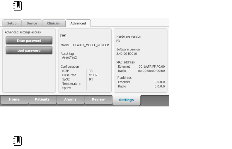
Authentication password Touch the keypad in the Authentication password
field and enter the User password. This is an alpha-
numeric string with a maximum length of 20
characters.
Search subtree Touch the keypad in the Search subtree field and
enter what you want to search in the Active
Directory. This is an alpha-numeric string with a
maximum length of 121 characters.
Test Touch Test to test the connection to the Active
Directory server.
Information messages indicate that a test is in
progress and then the result of the test (pass or fail).
5. Do one of the following:
• To continue in the Advanced settings, touch another tab.
• To exit the Advanced settings and return to the Home tab, touch Exit.
Service
Advanced settings and Service tabs
The Advanced tab provides password-protected access to the monitor's Advanced settings (or
Admin mode), enabling nurse administrators, biomedical engineers, and/or service engineers to
configure specific features. The Advanced tab also presents read-only information about the
monitor.
The password to enter Advanced settings is configurable and can also be set to expire. See the
"Password" topic at the end of this section for more details.
NOTE You cannot enter Advanced settings if sensors or physiological alarms are
active or if vital sign measurements are displayed.
Access the Service tabs
NOTE You cannot access the Service tabs if sensors or physiological alarms are
active or if vital sign measurements are displayed.
1. From the Home tab, touch the Settings tab.
2. Touch the Advanced tab.
3. Touch Enter password.
48 Advanced settings
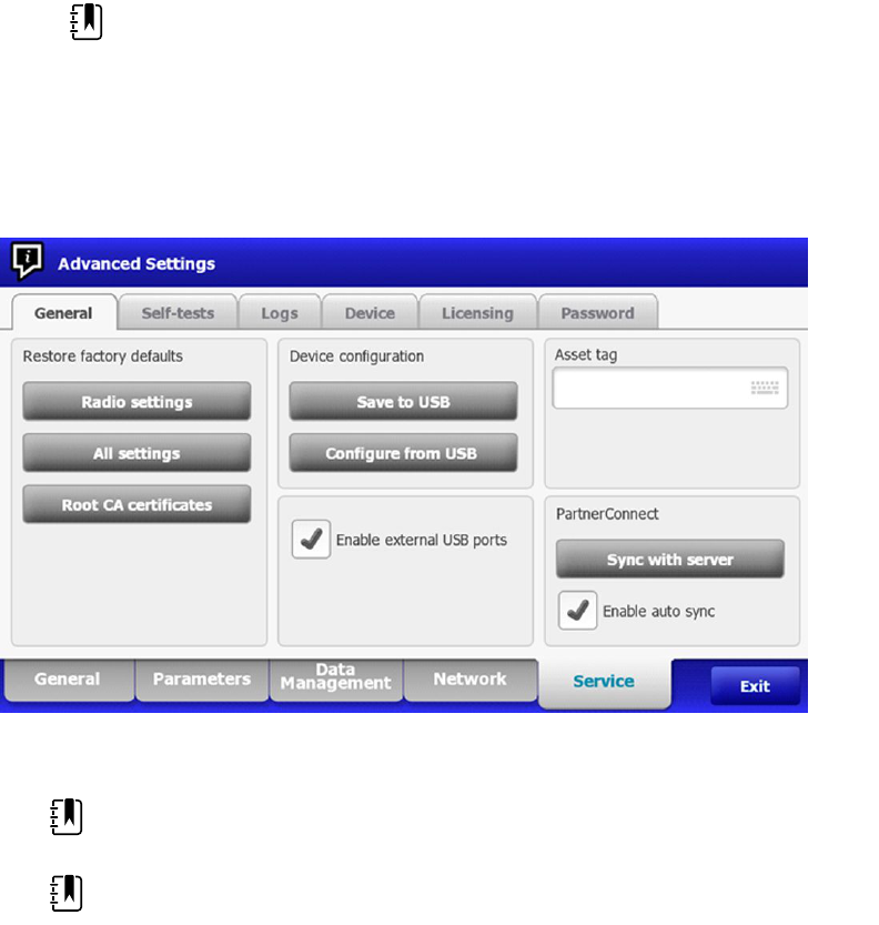
4. Enter 6345 , or the custom password for the device, as the access code and touch OK.
5. Touch the Service tab.
The General screen appears.
6. Perform service tasks by making selections or touching other tabs.
NOTE Service tasks and how to do them are detailed in this section.
7. When you are done, touch Exit.
The Home tab appears.
General tab
Restore factory default settings
NOTE This process deletes the custom data file. All custom data will be lost.
NOTE Restoring the radio default settings on a device equipped with a Newmar
radio will remove all installed wireless certificates.
1. Go to the Service tabs as described in “Access the Service tabs.”
2. Touch the General tab.
3. Restore factory default settings:
• To restore radio settings to factory default values, touch Radio settings.
• To restore all current settings to factory default values, touch All settings.
• To delete all root certificates currently installed, touch Root CA certificates.
A confirmation dialog appears.
4. Touch OK.
The factory default settings are restored.
If you selected Radio settings, the radio reboots, and the device remains powered on.
Service manual Advanced settings 49

If you selected All settings or Root CA certificates, the device reboots.
Save the device configuration or custom data to a drive
You can save the device configuration or custom data (custom modifiers and custom scoring) to a
USB flash drive. You can use the saved configuration to restore the device’s configuration or to
copy this configuration to use on other devices. You can use the saved custom data to restore
custom modifiers or custom scores, or you can copy them to another device.
NOTE Not all flash drives are supported.
NOTE When saving the device configuration, the location ID and asset tag
information are not included in the configuration file.
NOTE Save to USB does not support saving root CA and wireless certificates.
1. Connect a flash drive to the USB port.
2. Go to the Service tabs as described in “Access the Service tabs.”
3. Touch the General tab.
4. Touch Save to USB.
A confirmation dialog appears. You can save the device configuration or custom data if either
custom scores or custom modifiers are present.
5. Touch OK.
If the selected file or files already exist on the USB flash drive, a popup dialog appears with the
message "Device configuration file already exists. Select OK to continue with save and
overwrite existing file or cancel."
6. Touch OK to save the data to the USB drive or touch Cancel to exit without saving.
A confirmation message appears.
NOTE If the USB drive is incompatible, the message "Unable to save configuration
to USB" appears. Touch OK to continue.
NOTE The configuration file is saved as CONFIG.PMP. The custom data file is saved
as CUSTOMDATA.XML.
Load a device configuration, custom data, and/or root CA certificates
You can load a configuration from a USB flash drive to the device.
NOTE Not all flash drives are supported.
NOTE If your configuration includes radio parameters, make sure the radio is
enabled. The radio must be enabled before you can import radio parameters.
NOTE If a device setting is not available in the configuration file, the setting
returns to the factory default. This might be the case when the configuration file
was saved from a device with a different firmware version.
NOTE Configuration files cannot be cloned between devices with different host
software, except where the version change is minor.
1. Connect a flash drive to the USB port.
2. Go to the Service tabs as described in “Access the Service tabs.”
50 Advanced settings

3. Touch the General tab.
4. Touch Configure from USB.
A confirmation dialog appears.
5. Select Device configuration, Custom data XML, and/or Root CA certificates.
A confirmation dialog appears to confirm overwriting the existing configuration.
6. Select OK to proceed, or Cancel to quit.
The configuration from the USB flash drive overwrites the configuration on the device, and the
device reboots.
NOTE If device configuration data is not present on the USB drive, that option will
be disabled.
NOTE If custom modifiers are not present on the USB drive, that option will be
disabled.
NOTE If root CA certificates are not present on the USB drive, that option will be
disabled.
NOTE If the configuration file is incompatible, an "Unable to read configuration
from USB" message appears. This might be the case if the configuration file was
cloned from a device with different software version.
NOTE Configuration files can be edited or amended by loading the configuration
file onto the device, making changes to the configuration through the user
interface, and then saving the configuration file.
NOTE Lamarr radio configurations do not overwrite Newmar radio configurations,
and vice versa. A single configuration file can store configurations for both Lamarr
and Newmar radios. To create this file, first create the configuration file on a device
with one type of radio and save it. Then load the configuration file on a second
device with the other type of radio, configure the radio, and save the file. The
newly saved configuration file includes both the Lamar and Newmar radio
configurations, but the device activates only the configuration matching the
device's radio type.
Delete custom data
To delete custom data, you must restore the monitor to factory defaults. Restoring the monitor to
factory defaults also deletes all configuration settings.
To restore the custom configuration settings and/or custom data, save the configuration file and/or
custom data to a USB drive and reload the file(s) after restoring factory defaults.
To determine if custom data is loaded on the device, complete these steps:
1. Go to the Service tabs as described in "Access the Service tabs."
2. Touch the Device tab.
A Custom file line displays the configuration name and the cyclical redundancy check (CRC) in
the Firmware version column.
Enter an asset tag
You can enter an alpha-numeric identifier in the data field to serve as an asset tag for device
identification.
1. Go to the Service tabs as described in “Access the Service tabs.”
Service manual Advanced settings 51

2. Touch the General tab.
3. Touch and enter up to 20 characters.
4. Touch OK.
NOTE If the device language changes, the asset tag remains
unchanged.
Enable/disable external USB ports
The external USB ports are enabled by default. Disabling (unchecking) this option cuts off power
and data to the external USB ports, making them unavailable for connections and external storage.
1. Go to the Service tabs as described in “Access the Service tabs.”
2. Touch the General tab.
3. If the external USB ports were previously disabled, touch Enable external USB ports to
provide power to those ports.
A check now appears in the checkbox.
4. To disable the ports, touch Enable external USB ports.
The checkbox now is empty.
Send device information to PartnerConnect
The device sends technical information, such as log files, to PartnerConnect periodically. You can
also manually send this information at any time by following this procedure.
1. Go to the Service tabs as described in “Access the Service tabs.”
2. Touch the General tab.
3. Touch Sync with server.
4. If the Enable auto sync was previously disabled touch Enable auto sync to automatically
synchronize with the server.
A checkmark now appears in the checkbox.
Self-tests tab
Calibrate the touchscreen
This tab calibrates the touchscreen, if needed.
1. Go to the Service tabs as described in “Access the Service tabs.”
2. Touch the Self-tests tab.
3. Touch Start.
a. Touch the location indicated by the device. The device checks the current calibration. If
the location coordinates and touched location match, a Calibration Confirmation dialog
appears. Touch OK to finish.
b. If the locations do not match, a calibration failure dialog appears. Touch Calibrate, and
then touch the screen as indicated. When calibration is complete, a Calibration
Confirmation dialog appears. Touch OK to finish.
52 Advanced settings

Logs tab
View an error or event log
1. Go to the Service tabs as described in “Access the Service tabs.”
2. Touch the Logs tab.
3. View a log report.
• To view an error log, select Error.
• To view an event log, select Event.
Save error and event logs to a USB flash drive
This feature is available in software versions 1.71.03 and later.
You can save a copy of the error and event logs to a USB flash drive.
NOTE Not all flash drives are supported.
1. Connect a flash drive to the USB port.
2. Go to the Service tabs as described in “Access the Service tabs.”
3. Touch the Logs tab.
4. Touch Save to USB.
A confirmation dialog appears.
5. Touch OK.
Copies of both log files are saved to the drive.
Device tab
View device and module information
1. Go to the Service tabs as described in “Access the Service tabs.”
2. Touch the Device tab.
Device and module information appears for you to view.
Licensing tab
View device licenses
NOTE After activating a new license, restart the device to complete the activation
process.
1. Go to the Service tabs as described in “Access the Service tabs.”
2. Touch the Licensing tab.
A list of available licenses appears. Checks indicate installed licenses.
Service manual Advanced settings 53

Password tab
Advanced settings password and password reset
NOTE You cannot access the Service tabs if sensors or physiological alarms are
active or if vital sign measurements are displayed.
1. From the Home tab, touch the Settings tab.
2. Touch the Advanced tab.
3. Touch Enter password.
4. Enter 6345, or the custom password for the device, as the access code and touch OK.
Configure passwords
NOTE The keyboard for the Password tab is the English keyboard regardless of the
language configured on the device.
NOTE New passwords must meet length requirements to be accepted as valid.
NOTE The keyboard for the Password tab does not set the first character to upper
case.
NOTE If you forget or lose your password, you cannot access the Password tab.
Touch Lost password and then contact Hillrom Technical Support: hillrom.com/
en-us/about-us/locations/ and provide the code that appears on the screen. Enter
your password using the keyboard and touch OK.
1. Go to the Service tabs as described in “Access the Service tabs.”
2. Touch the Password tab.
3. To change the current password, touch Change password.
a. Enter a new password.
NOTE The password must have between 8 and 32 characters.
A "Re-enter password" dialog appears.
b. Touch OK and re-enter the new password to confirm the change.
Either a "Successful password change" or "Failed password change" dialog appears.
c. Touch OK and then proceed as needed. In the case of a failed password change, either try
again or cancel the operation.
4. To lock out a user after 10 consecutive incorrect passwords, touch Enable failed attempt
lockout.
NOTE The lockout period is 5 minutes.
5. To set an expiration for the current password, touch Enable password expiration, and then
enter the number of days after setting a password that it will expire.
Once a valid password is entered the Advanced tab appears.
54 Advanced settings

Power-up sequence
The system performs a power-on self test (POST) each time the device is powered on. During
power up, the device performs a comprehensive self test of the software. If software testing is
successful, the device then tests internal hardware. If all tests are successful, the system completes
power up and the Home tab appears.
To perform the POST:
1. Disconnect any patient cables connected to the device.
2. Insert a fully charged battery into the device.
3. Upon each power up, confirm the following:
a. The light bar flashes amber.
b. The startup screen appears.
c. A beep sounds, followed by one chime.
NOTE If no chimes sound, replace the speaker as specified in
“Remove the speaker.”
NOTE If no chimes sound, replace the speaker as specified in
“Replace the speaker.”
d. The product line logo appears at the bottom of the screen.
e. If a printer is installed, the paper advances slightly.
f. The Home tab appears.
WARNING Equipment failure risk. The device includes a fan that circulates air
through the device. If the fan does not run when you power up the device,
remove it from use and inform qualified service personnel immediately. Do not
use the device until the problem is corrected.
If the internal self-check is successful, the device shows its normal functions with all values blank
and the device is ready for operation. If the self-check fails, an error message appears in the Device
status area at the top of the screen. If a fault that could adversely affect the product is detected, the
device enters a safe mode and stops monitoring patients. The device remains in safe mode until it
is turned off or until it shuts down automatically after a period of inactivity.
If a system error is detected, the device becomes inactive until you press
or until the device
shuts down automatically. The device displays a system fault message that contains a wrench icon(
) and a system fault code to aid service personnel and engineers in diagnosing the problem.
While in safe mode, the red LED bar and the piezo buzzer cycle on and off.
55
56 Power-up sequence

Troubleshooting
This section provides the following tables to help troubleshoot the device.
• Symptoms and solutions: These tables list symptoms you might observe, list possible causes,
and suggest actions that may eliminate the problem.
• Technical alarm messages: These tables list messages generated by the device software
when a problem is detected. The tables explain possible causes and suggest actions that can
resolve the problem.
These tables can help you diagnose and fix a problem. They do not replace basic troubleshooting
skills. You must still trace the source of the problem to the board or module level to decide the best
course of action. Welch Allyn does not support component-level repair to the board or module. For
available replacement parts, see “Field Replaceable Units.”
WARNING Do not perform troubleshooting on a device that is emitting smoke or
exhibits other signs of excessive overheating. Disconnect the device from AC
power and call Welch Allyn Technical Support immediately.
CAUTION Replace parts, components, or accessories only with parts supplied or
approved by Welch Allyn. The use of any other parts can lead to inferior device
performance and will void the product warranty.
Symptoms and solutions
Power
Symptom Possible cause Suggested action
The device does not power up A new battery was installed Connect AC power to wake
up the battery.
The AC power is disconnected Connect AC power.
The power cord is defective Replace the power cord.
The battery is discharged Charge the battery.
The power button is defective Replace the power button.
An internal connection is faulty Check the power-flex cable
connection at J6 on the main
board.
57

Symptom Possible cause Suggested action
Check the AC power harness
connections from the IEC
connector to the power
supply.
Check the power harness
from the power supply J2 to
J30 on the main board.
Check the battery power
harness from J2 on the battery
connector board to J29 on the
main board.
The power supply is defective Check the output voltage on
the power supply. The voltage
should be 15 V ± 0.45V DC. If it
is not, replace the power
supply.
The battery is defective Charge the battery for 5 hours.
If the battery icon on the
display still shows an empty
battery symbol, replace the
battery.
The main board is defective Replace the main board.
The battery doesn’t charge or
run time is low
The battery is defective Charge the battery for 5 hours.
If the battery icon on the
display still shows an empty
battery symbol, replace the
battery.
The battery connector board is defective Check the battery connector
board for an open short or
broken connector and replace
if necessary.
The battery has reached the end of its useful
life
Use the service tool to check
cycle count. If the cycle count
exceeds 300, replace the
battery.
Hardware
Mechanical Symptom Possible cause Suggested action
Noisy fan Dust build up Use canned air to blow dust
out of fan.
Fan is out of balance Replace fan.
58 Troubleshooting

Mechanical Symptom Possible cause Suggested action
Cracks in housing Non-approved cleaning agents Replace plastic housing as
necessary.
Use only approved cleaning
agents.
Display
Symptom Possible cause Suggested action
The touchscreen does not
respond
Software error Reboot the device. Press and
hold the power button until
the device shuts down.
Note Any configuration
settings not saved as default
will be lost. Press the power
button to restart.
The touchscreen is out of calibration In Advanced Settings, touch
the Service > Self-tests tabs,
then recalibrate the screen.
The touchscreen lock is activated To unlock the touchscreen,
touch at the bottom of the
screen.
To disable the touchscreen
lock, touch the Settings >
Device tabs, then uncheck
Allow display lock timeout.
An internal connection is faulty Check the connection at J48
on the main board with
display flex cable.
A display flex cable is broken Replace the touchscreen and
display assembly.
The main board has a faulty touchscreen
controller
Replace the main board.
Excessive force or prolonged rubbing in an
area of the touchscreen
Replace the touchscreen.
The display is blank when the
power is on
The device is in Power-Saver mode Wake the display by touching
the screen or the power
button.
The device powered down after a period of
inactivity
Turn on the device by
pressing the power button. In
Advanced Settings, touch the
General > Display tabs, then
set Device power down to
the desired interval.
Service manual Troubleshooting 59

Symptom Possible cause Suggested action
An internal connection is faulty Check the display harness
connections at the display
and J19 on the main board.
Replace the cable if damaged.
A cable is damaged Replace the cable.
The display is dim The brightness setting is too low Increase the brightness
setting. Touch the Settings >
Device tabs, touch Defaults,
then set Display brightness
to the desired level.
The display has reached the end of its useful
life
Replace the display.
User interface
Symptom Possible cause Suggested action
Unable to access advanced
settings or enter the advanced
settings code
Patient monitoring is active or being
simulated
Discontinue patient
monitoring or stop the
simulation.
The parameter alarm is on Dismiss the alarm.
Intervals are turned on Stop intervals.
Desired profile does not appear
in the Profiles tab
The profile license is not installed In Advanced settings, touch
the Service > Licensing tabs.
Verify that the profile license
box is checked. If not,
purchase the license and
install it using the service tool.
The profile is not enabled In Advanced settings, touch
the Device tab, then check
the profile(s) you want to
enable.
60 Troubleshooting

Communication
Symptom Possible cause Suggested action
Cannot communicate through
the USB client connection
The battery charge is low Connect the device to AC
power and allow the battery
to fully charge.
The communications board does not
receive power
Check the voltage from J49 on
the main board for +5.0, ±0.5V
DC. Replace the main board if
necessary.
The USB client is defective Test the connection by
connecting a PC running the
service tool. Verify that the
service tool is configured
properly on the PC to
communicate with the device.
See the service tool help files.
Replace the power cable to
the communications board.
USB accessories do not
communicate with the monitor
The accessory is defective Replace with a known good
accessory.
The communications board is not receiving
power
Check the voltage from J49 on
the main board for +5.0, ±0.5V
DC. Replace the main board if
necessary.
One or more USB host connections are
defective
Test the connection with a
USB thumb drive. If no power
or enumeration is present,
such as an LED on a thumb
drive, replace the
communications board.
A USB connection from the communications
board to the main board is faulty
Verify that the USB cables are
connected correctly.
Replace the USB cables.
The device does not
communicate via Ethernet with
the computer network
The device is not configured properly Check the settings with your
network administrator.
The communications board is not receiving
power
Check the voltage from J49 on
the main board for +5.0, ±0.5V
DC. Replace the main board if
necessary.
The Ethernet connection from the main
board is faulty
Test the internal Ethernet
cable. Replace if necessary.
Verify that the shim is installed,
if required, on the Ethernet
cable connector at J11. See
the reassembly notes for the
main board.
Service manual Troubleshooting 61

Symptom Possible cause Suggested action
The network Ethernet switches are not set to
the correct speed to work with the device
Set the switches to 10 Mbps
full duplex.
The cable run to the switch is too long Use a shorter patch cable.
The radio does not connect to
the network
The device is out of range of the access
point
Check the network status
screen’s RSSI value.
The device is not configured properly Check the settings with your
network administrator.
The antenna is defective Check the antenna cable and
antenna connection. Replace
the cable and antenna if
necessary.
The communications board is not receiving
power
Check the voltage from J49 on
the main board for +5.0, ±0.5V
DC. Replace the main board if
necessary.
Alarms
Symptom Possible cause Suggested action
The light bar does not turn on No alarm was triggered Verify that the light bar flashes
when the system starts.
Verify that the alarm is
triggered by a visual indicator
in the message status area
and an audio alarm occurs.
There is a faulty connection Check the light-bar harness
and connections at the light
bar and J46 on the main
board. Replace the defective
cable if necessary.
The light-bar board is defective Apply +3.3V to pin 1 of the
harness and ground to pin 2.
Verify that the amber LEDs
illuminate. Connect the
ground to pin 3. Verify that
the red LEDs illuminate. If one
or both do not illuminate,
replace the LED light bar.
The main board is defective Verify that there are +3.3V at
pin 1 of J46 on the main
board.
No audible alarm occurs No alarm was triggered Verify that the alarm is
triggered by a visual indicator
in the message status area
62 Troubleshooting

Symptom Possible cause Suggested action
and light bar. Listen for
audible sounds on start up.
The alarm audio is set to Off Touch the Alarms > General
tabs, then select Alarm audio
on.
In Advanced settings, touch
the General > Alarms tabs,
then disable Allow user to
turn off general audio.
The alarm audio is set too low Touch the Alarms > General
tabs, then set Volume to the
desired level.
In Advanced settings, touch
the General > Alarms tabs,
then set Minimum alarm
volume to the desired level.
There is a faulty connection Check the speaker harness
and connections at the
speaker and J12 on the main
board. Replace the defective
cable if needed.
The speaker is defective Replace the speaker.
The main board is defective Test speaker output using an
oscilloscope on J12.
NIBP
Symptom Possible cause Suggested action
The NIBP frame on the display is
blank
The USB cable is defective Replace the USB cable.
The NIBP module is not connected Check the internal USB
connection.
The NIBP module is not functional Check the error logs for NIBP
errors. See the service tool
help files for details on specific
errors and suggested actions.
Check with Welch Allyn for
software updates.
If no NIBP error is logged, the main board
might be defective
Replace the main board if
necessary.
Service manual Troubleshooting 63

SpO2
Symptom Possible cause Suggested action
The SpO2 frame on the display
is blank
The USB cable is defective Replace the USB cable.
The SpO2 module is not connected Check the internal USB
connection.
The SpO2 module is not functional Check the error logs for SpO2
errors. See the service tool
help files for details on specific
errors and suggested actions.
Check with Welch Allyn for
software updates.
If no SpO2 error is logged, the main board
might be defective
Replace the main board if
necessary.
SpHb
Symptom Possible cause Suggested action
The SpHb frame on the display
is blank
The UI license is not installed. Purchase a license and install
the license using the service
tool.
The wrong sensor is connected. Use a sensor that supports the
SpHb parameter.
The sensor or cable expired. Replace the sensor or cable.
The sensor or cable is defective. Replace the sensor or cable.
The Masimo SpO2 module does not have
the SpHb parameter enabled.
Purchase the parameter and
install using the service tool.
The SpHb frame is unavailable The selected profile does not support SpHb. Change the profile to Intervals
Monitoring or Continuous
Monitoring.
ECG
Symptom Possible cause Suggested action
No LTA alarm associated with
patient injury or death
LTA license not installed Remove device from service,
contact Welch Allyn Technical
Support, and return to Welch
Allyn for service.
V-Tach, V- Fib, Asystole detection disabled
invalid data
64 Troubleshooting

Symptom Possible cause Suggested action
No LTA or ECG tile shows
Arrhythmia detection off
Alarms off in advanced settings Turn on alarms.
No license Install license.
ECG module unable to detect arrhythmias Contact Welch Allyn Technical
Support.
Replace the module if
necessary.
No ECG pane Module not connected Check ECG module LED.
Faulty patient cable Check cable.
Faulty module cable
CVSM software does not support ECG Update software.
Profile not set to Continuous Monitoring Set profile to Continuous
Monitoring.
ECG tile disabled Patient type set to Neonate Change patient type to Adult
or Pediatric.
No waveform Start button not activated Touch Start on ECG tile to
begin waveform streaming.
ECG gain too high Reduce ECG gain.
Patient type set to Neonate Change patient type to Adult
or Pediatric.
Noisy waveform 50 or 60 Hz filter disabled Enable filter.
Wrong mains filter value selected (50 Hz
versus 60 Hz)
Set the filter to the correct
mains frequency for your
location.
Poor lead placement See DFU for proper
placement.
No pacer or ECG tile shows
pacer detection off
Pacer detection Off Touch the Settings > Setup
tabs, then touch the ECG
vertical tab. Enable Patient
has a pacemaker.
ECG module unable to detect pacer Contact Welch Allyn Technical
Support.
Replace the module if
necessary.
No alarming snapshot was
auto-printed
Device does not have a printer None. Connex IWS does not
have a printer.
Service manual Troubleshooting 65

Symptom Possible cause Suggested action
Printed waveform is too small ECG gain and/or sweep speed is set too low Increase gain and/or sweep
speed and reprint.
Snapshot button is disabled An alarming snapshot is in progress Wait for up to one minute for
the button to enable.
Less than one minute has elapsed between
snapshots
Module LED off Module is not receiving power Replace cable.
Module LED yellow Internal error Power cycle device or
disconnect and then
reconnect cable.
Module LED steady green Module powered on Working as designed.
Module LED flashing green Sending data Working as designed.
Weight scale
Symptom Possible cause Suggested action
Weight does not appear in
manual parameter frame
The weight was not selected in Advanced
settings
In Advanced settings, touch
the Parameters tab, then
select Weight.
Note You can select only four
manual parameters.
The weight scale is not licensed Purchase a license and install
the license using the service
tool.
The weight scale is not connected Check cables and
connections. Use the service
tool to test connectivity.
Replace cables.
The weight scale is not configured Consult the scale directions
for use.
Temperature
Symptom Possible cause Suggested action
The temperature frame on the
display is blank
The USB cable is defective Replace the USB cable.
The temperature module is not connected Check the internal USB
connection.
The temperature module is not functional Check the error logs for
temperature errors. See the
service tool help files for
66 Troubleshooting

Symptom Possible cause Suggested action
details on specific errors and
suggested actions.
If no temperature error is logged, the main
board might be defective
Replace the main board if
necessary.
Braun ThermoScan PRO 4000 thermometer
Symptom Possible cause Suggested action
The thermometer batteries
don’t charge
The rechargeable battery pack no longer
takes a charge
Replace the rechargeable
battery pack.
Primary AA batteries are installed in the
thermometer
Replace the batteries with a
rechargeable battery pack.
The dock LED is green, but the
battery is low or depleted
Primary AA batteries are installed in the
thermometer
Replace the batteries with a
rechargeable battery pack.
The dock is defective Replace the dock.
Thermometer readings do not
transfer to the device
The external USB cable is unplugged Check the external USB
connection.
The USB bus has stopped communicating
with the Braun dock. (The device displays
wrench error #00000014.)
Reboot the host device.
NOTE For additional troubleshooting tips for the thermometer, see the
manufacturer’s product documentation.
Braun ThermoScan PRO 6000 thermometer
Symptom Possible cause Suggested action
Braun measurements are
inaccurate
Probe lens is displaced Examine lens for displacement. If
you observe a gap in the seam
between the bezel and the lens,
replace the thermometer.
Use inconsistent with DFU See DFU for proper operation.
Perform the Braun functional
verification test using the service
tool or the manual test described in
this manual. Replace as necessary.
Ingress of cleaning solutions has
corroded the electronics
Replace the thermometer. Review
cleaning procedures in the DFU.
Service manual Troubleshooting 67

Symptom Possible cause Suggested action
Temperature tile displays ++
Braun displays HI
Temperature taken is not within
typical human temperature range.
HI will be displayed when
temperature is higher than 108°F
(42.2°C).
Change probe cover to reset. Then,
make sure thermometer is properly
inserted and take a new
temperature.
Temperature tile displays - -
Braun displays LO
Temperature taken is not within
typical human temperature range.
LO will be displayed when
temperature is lower than 68°F
(20°C).
Braun displays “POS” error The infrared monitor cannot find a
temperature equilibrium and allows
no measurement.
Change the probe cover to reset.
Restrict patient movement and
ensure that the positioning of the
probe is correct and remains stable
while taking new temperature.
Braun displays “Err” error Ambient temperature is not within
the allowed operating range (50 –
104 °F or 10 – 40 °C) or changing
too rapidly.
Wait 20 seconds until thermometer
turns off automatically, then turn
on again. Ensure thermometer and
patient are in an environment for
30 minutes where the temperature
is between 50 °F and 104 °F or 10 °C
and 40 °C.
Braun display is blank or displays all
icons
System error
Wait 20 seconds until the
thermometer turns off
automatically, then turn on again. If
error persists, reset the
thermometer by removing the
batteries and putting them back in.
If error still persists, batteries are
dead. Insert new batteries.
If error still persists, contact local
Welch Allyn Service Center or
representative.
Braun displays Alert icon with “1” in
lower right corner
Technique Compensation
(PerfecTemp) technology is not
functioning or disabled
Open the temperature tab in
Advanced settings to configure
PerfecTemp*.
68 Troubleshooting

Symptom Possible cause Suggested action
Braun displays Alert icon with “U” in
lower right corner
Unadjusted Operating Mode is
enabled
Open the temperature tab in
Advanced settings to configure
Unadjusted Operating Mode*.
C/F button is not functional Celsius only enabled Open the temperature tab in
Advanced settings to disable
Celsius only selection*.
Pulse timer button is not functional Pulse timer disabled Open the temperature tab in
Advanced settings to enable pulse
timer*.
Braun displays lock icon and is
unresponsive
Security mode enabled and anti-
theft timer has expired
Return Braun thermometer to dock
to unlock. Security mode is set on
temperature tab in Advanced
settings.
Braun display is blank after
performing upgrade
Software upgrade was interrupted Remove and replace the battery
while holding the C/F button or
return to the dock while holding
the C/F button. Retry upgrade.
*Host device Braun 6000 settings override configuration settings from Welch Allyn Service Tool.
NOTE For additional troubleshooting tips for the thermometer, see the
manufacturer’s product documentation.
Manual parameters
Symptom Possible cause Suggested action
The manual parameter frame
does not appear on the Home
tab
No manual parameters are selected in
Advanced settings
In Advanced settings, touch
the Parameters tab, then
select the desired manual
parameters.
Note You can select only four
manual parameters.
BMI is not displayed The BMI parameter is not selected Select the BMI parameter in
the advanced settings.
Height or weight was changed Adjusting the height or
weight clears BMI.
Weight scale not connected BMI is available only from a
weight scale with height.
Service manual Troubleshooting 69

Printer
Symptom Possible cause Suggested action
The printer does not print The reactive side of the thermal paper does
not face the print head
Reverse the printer paper.
The thermal paper is wet Clean and dry the inside of the
printer housing and replace
the printer paper.
The USB cable is defective Replace the USB cable.
The printer module is not connected Check the internal USB and
power harness connection.
The printer does not have power Check J17 on the main board.
For more information, see
“Interconnect diagram.”
The printer module does not function Replace the printer module.
The power harness is defective Test the power harness.
Replace if necessary.
If no printer error is logged, the main board
may be defective
Check the error logs for
printer errors. Replace the
main board if necessary.
The printer fuse has blown; check MCE
printer fuse F5
Replace the MCE PCBA.
Barcode reader
Symptom Possible cause Suggested action
The barcode reader powers on
but does not transfer data
No license is installed Purchase a license and
install the license using
the service tool.
The barcode reader is not programmed to use
USB Com Port Emulation mode
Refer to the
manufacturer's
documentation to
program the barcode
reader to USB COM Port
Emulation mode.
The barcode reader is not supported For Honeywell model
4600g barcode readers,
verify that the PID is set to
020A.
The barcode scanner did not enumerate
properly
Power cycle the Connex
device.
70 Troubleshooting

Symptom Possible cause Suggested action
The patient ID or clinician ID do
not match
The barcode scanner is not programmed to
properly interpret the barcode
Program the barcode
scanner to turn on
required symbology and
to also add or delete
characters to form correct
ID.
Errors
Symptom Possible cause Suggested action
#000000001 An internal software error Power down and restart. If the
error persists, call Welch Allyn
Technical Support for service.
#000000002 An unclassified hardware error
#000000003 Graphics RAM POST
#000000004 System RAM POST
#000000005 Watchdog POST
#000000006 FLASH initiation failed
#000000007 A display system error
#000000008 A real-time clock error
#000000009 An audio system error
#000000010 An Ethernet system error
#000000011 The touchscreen controller failed
#000000012 Five or more SMBUS errors over a 1-minute period
occurred
#000000013 The communications module or main board failed
#000000014 Main board USB hub failure
#000000015 Software watchdog timer reset
Technical alarm messages
This section presents tables of technical alarm and information messages to help you troubleshoot
issues on the device. For information about physiological, dialog, or informational messages, see
the device’s directions for use.
When the device detects certain events, a message appears in the Device Status area at the top of
the screen. Message types include the following:
• Information messages appear on a blue background.
Service manual Troubleshooting 71

• Very low-priority alarms appear on a cyan background.
• Low- or medium-priority alarms appear on an amber background.
• High-priority alarms appear on a red background.
Technical alarm messages are low priority or very low priority unless noted in the Message column.
You can dismiss a message by touching the message on the screen, or, for some messages, you
can wait for the message to time out.
To use these tables, locate the message that appears on the device in the left column of the table.
The remainder of the row explains possible causes and suggests actions that can resolve the issue.
If you cannot resolve the issue, use the service tool to read the error log files or use the service tool
to perform a functional test
1
on the module reporting the message.
NIBP messages
Message Possible cause Suggested action
Alarm
NIBP air leak; check cuff and
tubing connections.
The NIBP module has an air leak Check the cuff, tubing, and
connections for leaks. If no
leaks are found, retake the
measurement. If the message
reappears, replace the NIBP
module.
NIBP not functional. Call for
service.
Internal errors or messaging errors occurred Check the error logs for NIBP
errors. See the service tool
help files for details on specific
errors and suggested actions.
Check with Welch Allyn for
software updates.
The ambient temperature is out of range Use the monitor in the
specified temperature range.
Unable to determine NIBP;
check connections; limit patient
movement.
Pressure exceeded the maximum limit for
this patient mode
Check connections; limit
patient movement.
Clear the alarm and retry NIBP.
Unable to determine NIBP;
check connections and tubing
for kinks.
NIBP tubing on the outside of the device is
kinked
Check the connections and
tubing for kinks.
Clear the alarm and retry NIBP.
The NIBP module needs to be calibrated Perform NIBP calibration.
Tubing inside the NIBP module is kinked Replace the NIBP module.
Incorrect NIBP cuff size; check
patient type.
A neonate cuff is in use with the monitor in
adult or pediatric mode
Check the patient type and
cuff size.
Clear the alarm and retry NIBP.
1
Requires the service tool, Gold licensed edition.
72 Troubleshooting

Message Possible cause Suggested action
Inflation too quick; check NIBP
cuff and tubing connections.
NIBP inflation was too quick Check the connections and
tubing for kinks.
Clear the alarm and retry NIBP.
Unable to determine NIBP;
check inflation settings.
Target pressure was too low Check inflation settings and
change as necessary.
Clear the alarm and retry NIBP.
Change the inflation setting.
Too many attempts Change the inflation setting.
Information
User cancelled NIBP reading. Blood pressure reading cancelled by user
Touch OK to dismiss.
Touch NIBP Start button to
dismiss and restart the NIBP
reading.
Tube type does not match
device configuration.
(NIBP measurement is available)
The tube type connected to the monitor
does not match the NIBP configuration.
Touch OK to dismiss.
Configure the NIBP advanced
settings to match the tube
type, patient type, and
algorithm.
The single lumen switch on the NIBP
connection is stuck
Use a small screw driver to
press the switch in and release
until the spring returns the
switch to the dual-lumen
position.
Excessive patient movement. The NIBP reading was deemed not precise
Touch OK to dismiss.
Limit patient movement and
restart the NIBP measurement.
SpO2 and SpHb messages
Message Possible cause Suggested action
Alarm
SpO2 not functional. Call for
service.
The sensor is defective Replace the SpO2 sensor with
a known good sensor.
An internal error occurred Update the host software to
the current version.
Check the error logs for SpO2
errors. See the service tool
help files for details on specific
errors and suggested actions.
Service manual Troubleshooting 73

Message Possible cause Suggested action
Check with Welch Allyn for
software updates.
Attach SpO2 sensor to monitor. The sensor was not detected Check the sensor connection.
Replace the sensor.
Replace the SpO2 sensor. The sensor is faulty Replace the sensor.
The sensor expired (applies only to SpO2 /
SpHb sensors)
Replace the sensor.
No sensor is connected Connect the sensor.
The patient cable is faulty Replace the cable.
The SpO2 module is faulty Verify module functionality by
replacing the sensor with the
applicable SpO2 tester. If the
message persists after you
have installed the SpO2 tester,
replace the module.
Searching for SpO2. (High-
priority alarm)
The SpO2 sensor is not attached to the
patient’s finger
Touch the alarm icon or the
SpO2 frame to dismiss the
alarm.
Set the SpO2 Alarm limits to
Off.
Reattach the SpO2 sensor to
the patient's finger.
Low SpO2 signal quality. Check
sensor.
Low SpHb signal quality. Check
sensor.
Low perfusion. Check sensor.
Poor sensor placement on the patient. Remove the sensor from the
patient and reapply.
The patient cable or sensor is defective Replace the patient cable or
sensor.
The SpO2 module is faulty Verify module functionality by
replacing the sensor with the
applicable SpO2 tester. If the
message persists after you
have installed the SpO2 tester,
replace the module.
SpO2 mode only. Check sensor
or cable.
The sensor is operating as an SpO2-only
sensor because it failed to calibrate properly
Reattach the cable to the
monitor.
Remove the sensor from the
patient and reapply.
SpO2 sensor expires in...
Note This message appears
only on devices configured with
SpHb.
The sensor will expire soon Replace the sensor.
74 Troubleshooting

Message Possible cause Suggested action
Replace the SpO2 cable. The cable is not functioning properly Replace the cable.
The SpO2 module is faulty Verify module functionality by
replacing the sensor with the
applicable SpO2 tester. If the
message persists after you
have installed the SpO2 tester,
replace the module.
Temperature messages (SureTemp)
Message Possible cause Suggested action
Alarm
Connect temperature probe. No probe is connected Connect a temperature probe
and retry.
The probe is faulty Replace the temperature
probe.
The temperature module returned a connect
probe message
Connect a temperature probe
and try again. If a probe is
already connected, replace
the probe.
The SureTemp temperature module is faulty Verify module functionality by
replacing the temperature
probe with the CAL-KEY
assembly. If the message
persists after you have
installed the CAL-KEY
assembly, replace the module.
Insert correct color-coded
probe well.
The probe well is missing Insert a temperature probe
well.
The SureTemp temperature module is faulty Verify that the lever arm on
the back of the probe well
housing is engaging switch
SW1 on the temperature
PCBA. If the problem persists,
replace the module.
Replace temperature probe. The probe is faulty Replace the temperature
probe.
The SureTemp temperature module is faulty Verify module functionality by
replacing the temperature
probe with the CAL-KEY
assembly. If the message
persists after you have
installed the CAL-KEY
assembly, replace the module.
Service manual Troubleshooting 75

Message Possible cause Suggested action
Retry temperature
measurement.
Note This message often
accompanies other
temperature messages.
A probe heater or data error occurred Retry the temperature
measurement. If the problem
persists, replace the probe.
User settings require adjustment Adjust the user settings and
retry.
The ambient temperature is out of range Operate the monitor within
the specified temperature
range. Retry patient
temperature measurement.
The SureTemp temperature module is faulty Verify module functionality by
replacing the temperature
probe with the CAL-KEY
assembly. If the message
persists after you have
installed the CAL-KEY
assembly, replace the module.
Temperature time limit
exceeded. Retry temperature
measurement.
The direct mode timed out Return the temperature probe
to the probe well and retry
measurement.
Information
Tissue contact lost. Lost tissue contact while attempting to
acquire temperature reading or acquired
reading was performed with limited tissue
contact
Touch OK to dismiss the
message. Start a new
temperature reading.
76 Troubleshooting

Temperature messages (Braun ThermoScan PRO)
Message Possible cause Suggested action
Alarm
Unable to detect temperature.
Retry measurement.
Measurement was not taken
Measurement recalled from memory
Retry measurement.
Loose or broken USB cable
Check USB connection and
cable.
Replace as necessary.
Dead battery
Braun display is blank or battery icon shows
one bar
Recharge or replace battery.
Braun displays “POS” error
Change the probe cover to
reset.
Restrict patient movement
and ensure that the
positioning of the probe is
correct and remains stable
while taking new
temperature.
Braun displays “Err” error
Ambient temperature is outside the allowed
operating range (50–104 °F or 10–40 °C) or
changes too rapidly
Wait 20 seconds until
thermometer turns off
automatically, then turn on
again. Ensure thermometer
and patient are in an
environment for 30 minutes
where the temperature is
between 50 ºF and 104 ºF or
10 ºC and 40 ºC.
Thermometer might be docked
improperly.
Thermometer is not properly docked Re-dock thermometer.
Thermometer has dirty contacts Clean dock and thermometer
contacts with 70 percent
isopropyl alcohol. See
Cleaning Instructions for
Braun ThermoScan PRO 6000.
Braun temperature not
functional.
Call for service.
Communication timeout
BDD transfer took longer than expected
POST did not complete or failed within the
expected time period
Remove and replace battery
to reset, then return
thermometer to dock.
If error persists, return for
service.
Service manual Troubleshooting 77

Message Possible cause Suggested action
POST failure
Braun display is all icons or blank
Unsupported parameter
Sensor data definition error (occurs when
the proxy is unable to set parameters to the
sensor using local DDS)
WACP serialization failure
Braun maximum battery voltage exceeded
Battery voltage is too high
Braun BDD compatibility
Braun BDD unexpected compatibility
Braun send message failure
Braun bridge failure
Temperature is not functional.
Call for service.
An internal error occurred Check the error logs for
temperature errors. See the
service tool help files for
details on specific errors and
suggested actions.
Check with Welch Allyn for
software updates.
The USB cable is disconnected Check the USB cable.
The battery is depleted or missing Replace the batteries.
ECG messages
Message Possible cause Suggested action
Alarm
Electrodes off: Device is configured for 5 leads, but
you are using 3 leads
Ensure that the device is
configured for the
appropriate number of
leads in Advanced
settings.
IEC electrodes (N, F, R, L, C) (N, F, R, L, C) disconnected Connect (N, F, R, L, C)
lead.
78 Troubleshooting

Message Possible cause Suggested action
AHA electrodes (RA, LA, LL, V) (RA, LA, LL, V) disconnected Connect (RA, LA, LL, V)
lead.
Electrode x off. One lead is disconnected Check the connections
of all leads.
ECG not functional. ECG module error, WACP error, Data
failure
Check the USB cable
and connections.
Perform functional test.
If the test fails, contact
Customer Care and
replace the ECG module
if necessary.
ECG module has not transmitted
ECG data for the past 30 seconds
Check the USB cable
and connections.
Perform functional test.
If the test fails, contact
Customer Care and
replace the ECG module
if necessary.
ECG module disconnected Check the ECG module
connection to Connex
device.
Unexpected alarm compatibility
bits
Restart the Connex
device and the ECG
module; if the error
persists, contact
Customer Care.
Perform functional test.
If the test fails, contact
Customer Care and
replace the ECG module
if necessary.
Cannot analyze ECG. Module unable to analyze the ECG
signal for V-Tach, V-Fib, and/or
asystole
Check electrodes and
leads, and replace as
needed.
Check the patient cable
connection to the ECG
module.
Perform functional test.
If the test fails, contact
Customer Care and
replace the ECG module
if necessary.
Cannot measure ECG. ECG module has been unable to
detect and ECG waveform for the
past 30 seconds
Check electrodes and
leads, and replace as
needed.
Service manual Troubleshooting 79

Message Possible cause Suggested action
Check the patient cable
connection to the ECG
module.
Perform functional test.
If the test fails, contact
Customer Care and
replace the ECG module
if necessary.
Searching for respiration. ECG unable to measure patient
respirations
Check electrodes and
leads, and replace as
needed.
Check the patient cable
connection to the ECG
module.
Perform functional test.
If the test fails, contact
Customer Care and
replace the ECG module
if necessary.
You are not using Lead II to view
respiration
Ensure that you are
viewing Lead II for
respiration.
Attempting to acquire ECG/
Impedance respiration
Check electrodes and
leads, and replace as
needed.
Check the patient cable
connection to the ECG
module.
Perform functional test.
If the test fails, contact
Customer Care and
replace the ECG module
if necessary.
Respiration alarm limits changed. Respiration physiological alarm
limits were modified because the
respiration source changed
Reset alarm limits.
Weight scale messages
Message Possible cause Suggested action
Weight scale not functional. Call
for service.
The weight scale is not operating properly Check the scale.
Use the service tool to check
connectivity with adapter.
Replace cables.
80 Troubleshooting

Message Possible cause Suggested action
Replace adapter.
Communications module messages
Message Possible cause Suggested action
Communications module did
not power on properly. Power
down the device. (High-priority
alarm)
The communications board is not
connected properly to the main board
Check the USB connection at
J4. Check the Power
connection at J50. Check the
voltage from J49 on the main
board for +5.0V ±0.5V DC.
Replace the main board if
necessary.
The communications board malfunctioned Replace the communications
board.
Radio messages (Lamarr)
Message Possible cause Suggested action
Alarm
Radio not functional. Call for
service.
A hardware failure occurred Replace the radio.
The radio has the wrong software Update the radio software.
Radio error. Power down and
restart.
The monitor and the radio failed to establish
communication with each other
Power down and restart the
monitor.
If the problem persists, check
the following:
• The USB and power
connections from the
main board to the
communications board.
• The connection from
the radio board to the
communications board.
• Monitor and radio
software compatibility.
Replace the radio if necessary.
Unable to establish network
communications. Radio out of
network range.
The radio is no longer communicating with
the access point
Verify that the monitor is
within the radio coverage
area. Verify that the radio is
correctly configured to the
network. If this message
appears intermittently, check
the RSSI value.
Service manual Troubleshooting 81

Message Possible cause Suggested action
Unable to establish network
communications. Call for
service.
Unable to get an IP address from the DHCP
server
Verify that a DHCP sever is
available on the network. The
monitor requires an IP address
from a DHCP server.
Radio Software upgrade failed. The connection with the host was broken Re-establish the connection
and try again.
The radio was not provisioned correctly Reset radio to factory defaults
and try again.
Hardware error Replace the radio.
Information
Radio software upgrade in
progress. Do not shut down.
Radio software is being written to the radio Do not interrupt the upgrade
until complete.
Radio card rebooting; please
wait.
The radio is restarting as part of the software
upgrade
Do not interrupt the upgrade
until complete.
Radio messages (Newmar)
Message Possible cause Suggested action
Alarm
Radio not functional. Call for
service.
Internal radio/communication error Reboot radio. If error persists,
reinstall software.
If error persists after
reinstalling software, check for
a software update and apply
it.
If error persists after updating
software, replace the radio.
Unable to establish network
communications.
Unable to associate with access point after
30 seconds
Check radio configuration.
Consult IT and check network.
Unable to authenticate after 30 seconds Check radio configuration.
Consult IT and check network.
If using FIPS, verify that
authentication types are
compatible with FIPS.
Radio card DHCP timeout. Unable to establish communications
between radio and DHCP server (network)
Check DHCP server.
Check radio configuration
settings.
82 Troubleshooting

Message Possible cause Suggested action
DHCP request timed out before obtaining
DHCP address
Invalid radio configuration.
Reconfigure and try again.
Radio configuration error Consult IT to verify that
wireless radio settings match
network settings.
If using FIPS, verify that
authentication types are
compatible with FIPS.
If problem persists, reset to
factory defaults.
If problem persists after
factory reset, check for a
software update and apply it.
If problem persists after
updating software, replace the
radio.
Lost network communications.
Radio out of network range.
Radio was communicating but is out of
range, lost power, or for some other reason
is no longer able to continue
communications with the access point
Move device into network
coverage area.
Check access point and
ensure it is powered on.
Verify that RSSI value is greater
than -65 dbi.
Verify wireless radio settings.
Check network configuration.
Configuration invalid without
certificates. Install certificates
and try again.
Radio configuration certificate error Verify that certificate settings
are correct and not expired.
Load certificates.
Verify radio configuration
settings and authentication
types.
If problem persists, reset to
factory defaults and reload
certificates.
If problem persists after
factory reset, check for a
software update and apply it.
If problem persists after
updating software, replace the
radio.
Service manual Troubleshooting 83

Message Possible cause Suggested action
Information
Certificate load failed. Radio customer certificate did not load Check that certificate includes
all required items.
Check certificate server log.
Certificate load successful. Radio customer certificates loaded
successfully from the host
No action required.
Ethernet messages
Message Possible cause Suggested action
Alarm
Network not found; check
network cable connection.
A network cable is unplugged Check the network cable
connection.
A network connection is broken elsewhere Check network wiring.
USB messages
Message Possible cause Suggested action
Alarm
External device not recognized. An unrecognized external device is
connected
Reconfigure the external
device.
Replace the external device.
Disconnect the unsupported
device.
USB Communication failure. Call
for service
An internal or external device is connected
but failed enumeration
Power down and restart.
Check the external device.
Check external and internal
USB connections.
Information
External device not licensed for
use.
A device requiring a license has been
connected to the USB connection
Obtain an authorization code
from Welch Allyn to activate
the license.
Unable to save configuration to
USB.
There was a problem writing the
configuration file to the USB flash drive
Use a Welch Allyn approved
flash drive.
84 Troubleshooting

Message Possible cause Suggested action
Verify that the flash drive is
not locked.
Verify that there is space
available on the flash drive.
Unable to read configuration
from USB.
There was a problem reading the
configuration file to the USB flash drive
Restart and try again.
USB accessory disconnected. The USB cable between an external device
and the monitor is disconnected
Confirm that the USB cable is
connected to the device and
the monitor.
System messages
Message Possible cause Suggested action
Alarm
Set date and time. The date or time is not set Set the date and time.
The date or time is not set properly Reset the date or time.
Incompatible Welch Allyn
device.
A known USB device enumerates, but fails The device may be faulty. Test
a known good device.
Unexpected restart occurred.
Call for service.
A system error caused the monitor to restart Check Event and Error logs.
Run the service tool
verification test.
Information
Device shutdown is not
available at this time.
The device cannot perform an immediate
shutdown
Touch OK to dismiss
message. If any process is
active, wait for it to complete
before attempting shutdown.
If the device is unresponsive,
hold down the power button
until device shuts down.
Note Any configuration
changes not saved as default
are lost.
Battery power manager messages
Message Possible cause Suggested action
Alarm
Service manual Troubleshooting 85

Message Possible cause Suggested action
Low battery 5 minutes or less
remaining. (High-priority alarm)
Battery power is extremely low Plug the monitor into AC
power. If not plugged in, the
monitor automatically powers
off.
Battery is absent or faulty. There is no battery in the monitor Insert a battery.
Battery is absent or faulty. Call
for service.
The battery is faulty Replace the battery.
Low battery 30 minutes or less
remaining.
The battery power is low Touch the alarm icon to
dismiss or plug the monitor to
AC power.
Information
Device is operating in battery
mode.
The AC power cord has been disconnected Touch the alarm icon to
dismiss or plug the monitor to
AC power.
Configuration Manager messages
Message Possible cause Suggested action
Alarm
Unable to load configuration;
using factory defaults.
A configuration load error occurred Restore factory defaults. If the
error persists, replace the main
board.
Functional error. Call for service. A critical configuration load error occurred Replace the main board.
Information
No connection for send. The monitor is not configured to the
network
In Advanced settings, touch
the Data Management >
Clinical Data tabs, then
disable Automatically send
on manual save if you only
want to store readings on the
device.
If your want to send readings,
then configure the device to
the network.
86 Troubleshooting

Patient data management messages
Message Possible cause Suggested action
Alarm
Maximum number of patient
records saved. Oldest record
overwritten.
The maximum number of patient records
has been saved on the device
Go to the Review tab and
delete old records to prevent
the alarm from appearing
when new records are saved.
Information
No data saved. No patient data is available Take or enter vital signs before
saving.
Patient ID required to save data. The configuration requires a patient ID to
save data
In Advanced settings, touch
the Data management >
Patient tabs, then disable
Require patient ID to save
readings.
Clinician ID required to save
data.
The configuration requires a clinician ID to
save data
In Advanced settings, touch
the Data management >
Clinician tabs, then disable
Require clinician ID to save
readings.
Patient ID required to send
data.
The configuration requires a patient ID to
send data
Add a patient ID.
Patient list is full. Delete some
patients to add more.
The maximum number of patients was
exceeded
Delete a patient from the list
to add a new patient.
Stop intervals to select new
patient.
The device is set to take interval readings Stop intervals before
changing the patient.
No connection for send. No connectivity is available to support
sending data manually or automatically
sending data on manual save
Check the network
connection.
Check the Radio
Configuration settings.
Unable to identify clinician. The clinician ID or password is incorrect Confirm the clinician ID and
password (if applicable), and
retry.
Unable to retrieve list. The device is unable to retrieve a patient list
from the network
Check the network
connection.
Check the Radio
Configuration settings.
Verify that the server is
available.
Service manual Troubleshooting 87

Network messages
Message Possible cause Suggested action
Lost connectivity with host. The central station or other
host application has stopped
running or is not operating
properly
Confirm that the host
application is running properly.
Failed to authenticate to server. Device is configured for server
authentication, but server
authentication failed for one of
the following reasons:
• the domain name of the
server does not match
the one reported in the
server certificate
• the certificate is expired
(no longer within the
validity period)
• the certificate has not
been verified
• the certificate has been
revoked
Make sure server certificates are
valid.
Make sure the correct CA
certificate file exists on the
device to authenticate the
server certificate.
Check the server configuration.
Make sure authentication is
configured correctly.
The server is not configured for
authentication
Disable the server
authentication option on the
device.
88 Troubleshooting

Disassembly and repair
This chapter is divided into two major subsections, defined in the table below.
Section A Section B
(IEC 60601 3rd- and 4th-edition compliant)
Devices meeting these criteria:
• Manufactured before 11/2017*
• MCE hardware version P3 or earlier
(see the right pane on the Advanced Settings
tab)
• Built before serial number* 100043244817
3rd-edition devices meeting these criteria:
• Manufactured after 11/2017*
• MCE hardware version P5 or later
(see the right pane on the Advanced Settings
tab)
• Built after serial number* 100043244817
4th-edition devices meeting these criteria:
• Manufactured after 12/2018**
* See "Monitor serial number and model label" in the Appendix for serial number format and meaning.
**See Customer Service Bulletin 80022414 CSB – CVSM/CIWS IEC 60601 4th Edition for the exact
manufacturing cutoff and start dates as well as the serial number for the first 4th-edition device.
Section A Section B
(IEC 60601 3rd- and 4th-edition compliant)
Devices meeting these criteria:
• Manufactured before 11/2017*
• MCE hardware version P3 or earlier
(see the right pane on the Settings tab)
• Built before serial number* 100023374817
3rd-edition devices meeting these criteria:
• Manufactured after 11/2017*
• MCE hardware version P5 or later
(see the right pane on the Settings tab)
• Built after serial number* 100023374817
4th-edition devices meeting these criteria:
• Manufactured after 12/2018**
* See "Device serial number and model label" in the Appendix for serial number format and meaning.
**See Customer Service Bulletin 80022414 CSB – CVSM/CIWS IEC 60601 4th Edition for the exact
manufacturing cutoff and start dates as well as the serial number for the first 4th-edition device.
89

Examine your device to determine which subsection you should follow to complete disassembly
and repair procedures.
This overview includes exploded views of the rear housing and main chassis that include callouts
referencing the parts. These exploded views apply to both Section A and Section B, though certain
parts are labeled as specific to one section or set of devices and not the other. In the instructions,
numbers in parentheses refer to callouts in the exploded drawings. Except where otherwise noted,
the reassembly procedure is the reverse of the disassembly procedure.
This overview includes exploded views of the front externior and rear interior that include callouts
referencing the parts. These exploded views apply to both Section A and Section B, though certain
parts are labeled as specific to one section or set of devices and not the other. In the instructions,
numbers in parentheses refer to callouts in the exploded drawings. Except where otherwise noted,
the reassembly procedure is the reverse of the disassembly procedure.
Each part’s disassembly instructions may include one or both of the following subsections:
• Reassembly notes: This contains information specific to reassembly not addressed in the
disassembly instructions, especially when reassembly is not a simple reverse of disassembly.
• When replacing the component: This contains information specific to installing a new option
or replacement part.
WARNING Electrical shock hazard. Disconnect AC power before opening the
device. Disconnect and remove the battery before proceeding with disassembly.
Failure to do this can cause serious personal injury and damage to the device.
WARNING Electrical shock hazard. Disconnect AC power before opening the
device. Disconnect and remove the battery before opening the main chassis.
Failure to do this can cause serious personal injury and damage to the device.
WARNING Risk of fire, explosion and burns. Do not short-circuit, crush, incinerate,
or disassemble the battery pack.
WARNING Safety risk. Do not attempt to service the device when the device is
connected to a patient.
CAUTION Before disassembling the device or installing options, disconnect the
patient from the monitor, power down the device, disconnect the AC power cord
and any attached accessories (SpO2 sensors, blood pressure hoses and cuffs,
temperature probes, ECG modules, Braun docks, and barcode scanners) from the
device.
CAUTION Before disassembling the device or installing options, disconnect the
patient from the monitor, power down the device, disconnect the AC power cord
and any attached accessories (SpO2 sensors, blood pressure hoses and cuffs,
temperature probes, Braun docks, and barcode scanners) from the device.
CAUTION Remove the probe well in the temperature module prior to
disassembly.
CAUTION Perform all repair procedures at a static-protected station.
CAUTION When the device case is opened, regard all parts as extremely fragile.
Execute all procedure steps with care and precision.
CAUTION Observe screw torque specifications, especially with screws that secure
directly into plastic standoffs.
90 Disassembly and repair

CAUTION To avoid mismatching screws and holes, keep the screws for each
piece with that piece as you remove modules and circuit assemblies. It is possible
to mistakenly install machine screws in locations intended for plastite screws.
Plastite screws in this device have a Torx-pan head.
CAUTION After performing any of these procedures and prior to returning the
device to service, you must use the service tool, Gold licensed edition, to complete
the full suite of functional tests to ensure that all systems are operating within the
design specifications. For more information about these tests and the service tool,
see “Functional verification and calibration.”
If you do not have the service tool, contact Welch Allyn Technical Support.
NOTE EarlySense and CO2 can be installed only on the extended chassis.
For information about screws or connectors used in the device, see the Appendix.
Service manual Disassembly and repair 91
Required tools and equipment
• #1 Phillips bit
• #2 Phillips bit
• #10 Torx bit
• Torque driver calibrated for 2.5 in-lb ±0.25 in-lb
• Torque driver calibrated for 6.0 in-lb ±1.0 in-lb
• Torque driver calibrated for 7.5 in-lb ±0.5 in-lb
• Slotted screwdriver
• Tweezers
• Needle-nose pliers
• Spudger
• Tie-wrap tool
• Tie-wrap cutter
• Soft lens wipes
• Scissors or other cutting device
• Canned air
• Adhesive tape
• Pro Gaff tape
For information about screws and connectors used in the device, see the Appendix.
• #1 Phillips bit
• #2 Phillips bit
• #10 Torx bit
• 8mm socket
• Torque driver calibrated for 2.5 in-lb ±0.25 in-lb
• Torque driver calibrated for 6.0 in-lb ±1.0 in-lb
• Torque driver calibrated for 7.5 in-lb ±0.5 in-lb
• Torque driver calibrated for 12.0 in-lb ±1.0 in-lb
• Slotted screwdriver
• Tweezers
• Needle-nose pliers
• Spudger
• Tie-wrap tool
• Tie-wrap cutter
• Soft lens wipes
• Scissors or other cutting device
• Canned air
• A coin to open the battery door. Select a size that comfortably fits the slot.
• Pro Gaff tape
For information about screws and connectors used in the device, see the Appendix.
92 Disassembly and repair

Disassembly overview
The following chart provides an overview of the complete disassembly of the device. Most
disassembly activities require that you complete a subset of the steps detailed here. The flow chart
indicates the steps that must be completed in sequence to remove a particular component.
Because a different sequence of preliminary steps might be required to remove certain
components, you should use this flow chart as a reference at the start of every disassembly and
component replacement procedure. A list of preliminary steps presented at the start of each
disassembly topic provides the prerequisites for that disassembly task. (Some tasks in the flowchart
are optional, depending on the scope of disassembly.)
Service manual Disassembly and repair 93
94 Disassembly and repair

Section A
This section applies to devices manufactured before 11/2017, serial numbers before 100043244817,
and MCE hardware version P3 or earlier.
NOTE If your device does not meet these criteria, see Section B for the correct
disassembly and repair instructions.
NOTE See "Monitor serial number and model label" in the Appendix to learn how
to determine the manufacture date from the serial number.
If the MCE hardware version is P2 or P3, DO NOT replace any components with service kits with the
"3rd Ed" suffix. IEC 3rd Edition service kits are not compatible with hardware versions P2 and P3.
Service kits with the "4th Ed" suffix may be used on all devices running host software version 1.71.
03 or 2.20.00 and later with the exception of 107124 (SERV KIT, CVSM, SpO2 MOD, NELLCOR 4th Ed).
Use 107124 only on devices running host software version 2.41.xx or later.
This section applies to devices manufactured before 11/2017, serial numbers before 100023374817,
and MCE hardware version P3 or earlier.
NOTE If your device does not meet these criteria, see Section B for the correct
disassembly and repair instructions.
NOTE See "Monitor serial number and model label" in the Appendix to learn how
to determine the manufacture date from the serial number.
If the MCE hardware version is P2 or P3, DO NOT replace any components with service kits with the
"3rd Ed" suffix. IEC 3rd Edition service kits are not compatible with hardware versions P2 and P3.
Service kits with the "4th Ed" suffix may be used on all devices running host software version 1.71.
03 or 2.20.00 and later with the exception of 107124 (SERV KIT, CVSM, SpO2 MOD, NELLCOR 4th Ed).
Use 107124 only on devices running host software version 2.41.xx or later.
Power down the device
You can power down the device as follows: 1) on devices with 2.X software, briefly press the power
button on the housing and then following the onscreen prompts, or 2) on all devices, use onscreen
controls alone.
Option 1. After the device is powered up, briefly press of the power button to open an onscreen
dialog with the following options:
• Power down. Device behavior varies based on the active profile, whether or not patient trend
data is stored, and whether or not patient context is established. While servicing the device,
you need not be concerned about these details. They only matter to clinicians who are
monitoring patients and storing patient data.
95

• Sleep. The Sleep button clears the display and puts the device into Display power-saving
mode.
• Cancel. The Cancel button dismisses the dialog.
Touch Power down and complete the power-down procedure.
Option 2. To use onscreen controls alone to power down the device, follow these steps:
1. Touch the Settings tab.
2. Touch the Device tab.
3. Touch Power down.
NOTE The next three sections address disassembly and repair steps you can
complete without removing the device from the wall or removing the battery. All
steps presented after “Remove the system from the wall and remove the battery”
require powering down as well as removing the device from the wall and
removing the battery.
Remove the battery
Before removing the battery, power down the monitor as described in this manual and disconnect
the AC power cord.
1. Turn the monitor upside down to access the battery cover.
2. Locate the battery cover, indicated by .
3. Insert a coin into the slot and push to open. Choose a coin that fits comfortably into the slot.
4. Pull the battery out by pulling the battery label, which is visible when you open the battery
cover.
96 Section A

Remove the rear housing
No. Item No. Item
1 Rear housing 6 Communications door
2a USB label 4 USB host 7 Communications door captive screw
2b USB label 1 USB host (model 6300 only) 8 IEC connector
3a Nurse call label 14 Screw, M4 X 10 pan head with NYLOC
3b No nurse call label (model 6300 only)
Before you begin, power down the device, disconnect the AC power cord, and remove the battery
as described in this manual.
1. Lay the monitor face down on the antistatic mat.
2. Loosen the screw (7) to open the communications door (6).
3. Open the communications door (6) to access the rear housing screw.
4. Remove the four rear housing screws (14).
5. Stand the monitor on its feet with the display facing away from you.
6. Pull the top of the rear housing away from the monitor to access the rear housing cable
connections.
7. While supporting the rear housing, disconnect the following from the communications
module:
Service manual Section A 97

a. The Ethernet cable from J9.
b. The small USB connector from J4.
c. The large USB connector from J8.
d. The communications power cable from J50.
8. Continuing to support the rear housing, do the following at the power-supply cover:
a. Free the power supply and fan cable from the wire guide on the side of the power-supply
cover.
b. Disconnect the power supply cable from the power supply board at J2.
c. Disconnect the fan cable (A) from the main harness.
d. Separate the rear housing (1) from the monitor.
Once the rear housing is removed, choose which part of the monitor to work on:
• Rear housing components. For details, see “Disassemble the rear housing.”
• Main chassis. For details, see “Disassemble the main chassis.”
Reassembly notes
• Route the power cable and fan harness cables in the channel on the side of the power-supply
cover.
98 Section A

• Some communications boards have two large USB connectors. The large USB connector J8 is
the one closest to the mini USB connector J4. For reference, see the communications board
diagram in the appendices.
• When closing the case, verify that no wires are crushed or pinched before securing with
screws. After tightening the screws, examine the seam between the rear housing and the main
chassis to verify that there is no bulging. Bulging indicates that something is preventing the
mating surfaces from seating properly.
When replacing the rear housing
NOTE The rear housing replacement service kit is assembled with the comms
door, ground stud, ground lug plate, IEC connector, and AC power harness. It is
unnecessary to transfer these components from the old rear housing.
1. Follow the procedures to disassemble the rear housing and remove any components that you
intend to transfer to the replacement housing.
2. Connect the AC power harness to the IEC connector (8). See the reassembly notes for the
power supply.
3. Install the rear housing gasket (15), included in the rear housing service kit, into the slot in the
outer edge of the rear housing. To ease installation, use a small flat-blade screwdriver to assist
in pushing the seal into the channel.
4. Install any components removed from the old rear housing in the reverse order of the
disassembly instructions.
5. After reassembling the rear housing, install the USB client cover (40) as follows:
a. Place the USB client cover on a USB mini B cable with the tape facing out.
b. Peel off the tape to expose the adhesive.
c. Insert the USB cable into the client USB connection, press and remove the cable to adhere
the cover to the rear housing.
6. Install these labels:
• USB label (2a for models 6400, 6500, 6700, and 6800; 2b for model 6300) in the
communications door opening.
• Nurse call label (3a for models 6400, 6500, 6700, and 6800; 3b for model 6300) over the
nurse call connection.
Remove the communications door
NOTE If the communications door is missing or already removed from the device,
proceed to "When replacing the communications door."
WARNING Personal injury risk. Because removing the door might propel the pin
and spring into the air, wear safety glasses to complete these steps.
Before removing the communications door, power down the monitor, remove the battery, and
remove the rear housing as described.
1. Position the rear housing with the Ethernet connection side down on an antistatic mat.
2. Open the communications door perpendicular to the rear housing.
Service manual Section A 99

3. Use a spudger to push the pin upward until the pin clears the hinge.
4. Carefully remove the door from the rear housing.
When replacing the communications door
WARNING Personal injury risk. Because attaching the door might propel the pin
and spring into the air, wear safety glasses to complete these steps.
1. Insert a spring and two pins into the communications door as shown.
100 Section A

2. With the bottom of the door on the antistatic mat, insert the pin on the right side of the door
into the hinge of the rear housing.
3. Press the pin into the left side of the door and slide the door into the hinge of the rear housing
until it snaps into place.
Service manual Section A 101

Disassemble the rear housing
No. Item No. Item
1 Rear housing 20c Communications board for Newmar radio
(Models 6400, 6500, 6700, and 6800)
8 IEC connector 21a Radio board, Lamarr, 802.11a/b/g
10 Screw, plastite #4-20 X 0.500 Torx-pan head 21b Radio board, Newmar, 802.11a/b/g/n
15 Rear housing gasket (Norprene tubing) 22 Screw, M3 X 0.5, Phillips pan head
16 Antenna board 23 Power supply board
17 AC power harness 24 Antenna mounting foam block
18 Power supply cover 39 Antenna cable
19 Fan 40 USB client cover
20a Communications board (Model 6300) 97 Screw, M3x0.5x8, Pan Phillips (Small
Phillips screw)
20b Communications board (Models 6400, 6500,
6700, and 6800)
102 Section A
Service manual Section A 103
Remove the communications board
Before you begin, remove the following as described in this manual:
• Battery
• Rear housing
1. Lay the rear housing on its back on the antistatic mat.
2. Remove the four Torx screws (10) that secure the communications board (20a or 20b) to the
rear housing.
3. Remove the communications board by doing the following:
a. Lift the inside edge of the board until the USB connector clears the wire channel on the
power-supply cover.
b. Slide the board slightly toward the power supply and lift until the board contacts the wire
channel on the power-supply cover.
c. Lift the outside edge of the board until the side connectors clear the rear housing.
d. For monitors with a radio: rotate the board (without pulling on the antenna cable) slightly
counter-clockwise, pivoting on the upper left-hand corner. Turn the board over and set it
down outside the top of the case.
4. If replacing the communications board, remove the radio board (21) as described in “Remove
the radio board and antenna.”
Reassembly notes
• If the radio board was removed, reinstall it before reinstalling the communications board.
• To install the communications board, do the following:
1. Position the board over the standoffs with the inside edge of the board under the wire
channel on the power-supply cover until the outer edge drops into the rear housing.
2. Align the mini-USB external connector with the opening in the side of the rear housing.
3. Slide the mini-USB connector into the opening until the board rests on the standoffs.
When replacing the communications board
Install the radio board on the new communications board before installing the communications
board on the rear housing.
104 Section A

Remove the radio board and antenna
CAUTION Do not remove the radio antenna from the rear housing unless
replacing the radio and antenna or the rear housing.
Before you begin, remove the following as described in this manual:
• Battery
• Rear housing
• Communications board
1. If the monitor has a radio:
a. Turn the communications board over to access the radio board, taking care to avoid
straining the antenna cable.
b. If the original Lamarr radio (a/b/g band) is installed, remove the four small Phillips
(machine) screws securing the radio board to the communications board, as shown on
the left. If the Newmar radio (a/b/g/n band) is installed, remove the three small Phillips
(machine) screws securing the radio board to the communications board, as shown on
the right.
c. Hold the communications board with one hand while grasping the radio board at the
opposite end from the antenna connection and pull the radio board away from the
communications board.
2. (Perform this step only if you are replacing the radio or antenna.) Disconnect the radio antenna
cable from the radio board.
3. Remove the four Torx screws (10) securing the power-supply cover.
4. Remove the power-supply cover (18).
5. Use a soft tool such as a spudger to separate the foam block (24) from the inside of the rear
housing.
Service manual Section A 105

Reassembly notes
Route the antenna cable in the channel located at the top of the rear housing.
When replacing the radio board and antenna
1. If the antenna is removed, clean the rear housing and mounting surface with isopropyl alcohol.
2. The following illustration shows both Lamarr and Newmar radio and antenna boards. Attach
the antenna cable to terminal G on the radio board. Attach the other end of the cable to the
antenna on terminal PG.
3. Peel the backing off the foam block (24) and affix the foam block to the rear housing.
4. Expose the adhesive on the foam block. Mount the antenna (16) on the foam block with the
antenna cable (39) oriented under the board and in the wire channel above the power supply.
5. Route the antenna cable in the channel located at the top of the rear housing.
106 Section A

Remove the fan
Before you begin, remove the following as described in this manual:
• Battery
• Rear housing
1. Press the flanges on the sides of the fan harness connector and separate the fan connector
from the power-supply cover (18).
2. Depress the tab on the power-supply cover and slide the fan (19) over the tab and out of the
housing.
Reassembly notes
CAUTION Ensure that the fan is properly oriented. Air must flow toward the
power supply.
NOTE If the fan is dirty, use canned air to remove dust. Do not bend the fan
blades or otherwise damage the fan. If the fan is noisy and cleaning does not
reduce the noise, replace the fan.
• With the label facing down, slide the fan into the housing on top of the power-supply cover
until the tab on the cover holds it in place.
• Clip the fan harness into the power-supply cover so that the connector is oriented toward the
fan, as shown in the following figure.
Service manual Section A 107

Remove the power supply
Before you begin, remove the following as described in this manual:
• Battery
• Rear housing
1. Remove the four Torx screws (10) securing the power-supply cover.
2. Remove the power-supply cover (18).
3. Disconnect the following from the power supply:
• The (green) ground cable
• The AC power harness (17)
NOTE See "Remove the AC power harness" for instructions.
4. Remove the power supply.
108 Section A

Remove the AC power harness
NOTE Do not disconnect the AC power harness from the IEC connector unless
you are replacing it. Once you disconnect the AC power harness, you cannot reuse
it.
Before you begin, remove the following as described in this manual:
• Battery
• Rear housing
• Power supply
Disconnect the AC power harness from the IEC connector and grounding plate.
Reassembly notes
When replacing the rear case or AC power harness, route the wiring as follows:
• Connect blue to neutral (N), green to ground (GND), and brown to line (L).
N
GND
L
NOTE The power supply harness to IEC connector is rated for a single connection.
Replace the power supply harness if it has been disconnected from the IEC
connector.
NOTE In older devices, color coding of the line and neutral wires was reversed.
The color of the wiring has no impact on the functionality of the device and does
not require reversing the connection to the IEC connector. Reversing the
connection to the IEC harness would also require replacement of the power
harness.
The risk of not replacing the harness is considered minimal as the manual contains
a warning to disconnect the device from AC power before opening the case.
• Plug the ground cable from the IEC connector onto the ground plate in the position closest to
the IEC connector.
• Ensure that the green ground wires are routed over the blue and brown wires.
• Ensure that the grommet on the AC power harness is in the slot in the power supply cover.
• When replacing the power supply cover, ensure that the antenna cable is routed in the
channel located at the top of the rear housing.
Service manual Section A 109

• Ensure that the green ground wires are underneath the power-supply cover, as shown in the
next figure.
110 Section A

Disassemble the main chassis
Disassembly and reassembly procedures are the same for the standard chassis and extended
chassis, unless otherwise noted.
Configuration options
Standard chassis (left side)
Supports a maximum of two modules
Extended chassis (left side)
Supports a maximum of three modules
Components (back to front):
SpO2, NIBP
Blank, NIBP (6300, 6400, and 6500 only)
Components (back to front):
CO2, SpO2, NIBP
Blank, SpO2, NIBP
Service manual Section A 111

Extended chassis (right side) Supports a maximum of one module
NOTE The standard chassis is the same as extended chassis minus space for an EarlySense
module, so it is not presented here.
Components (front to back):
Power button, EarlySense, Ethernet RJ-45, USB client, Nurse call
Power button, Blank, Ethernet RJ-45, USB client, Nurse call
NOTE Monitors configured with RRa, SpHb, or CO2 cannot be configured with EarlySense.
NOTE Ethernet RJ-45 provides a hardwired connection to the computer network. USB
client provides a connection to an external computer for testing and software upgrades.
Nurse call provides a connection to the hospital nurse call system. (Not available on the
6300 model.)
112 Section A

Main chassis exploded view
More detailed views of main chassis components and tables identifying specific parts appear later
in this section preceding the associated disassembly and repair instructions.
No. Item No. Item
10
Screw, plastite #4-20 X 0.500 Torx-pan head
53
Temperature housing
14
Screw, M4 X 10 pan head with NYLOC
54
Probe well seal
25
Bottom housing metal chassis
55
Horizontal struts
Service manual Section A 113

No. Item No. Item
26
Speaker
56
Temperature mounting cover
27
Bottom housing
60
HSG clamp
28
Battery connector board
62
LCD frame
30
Battery door
63
Grommet, ear - G411-1
31
Handle insert
64
Shoulder screw, ear G-411-1 metric
32
Top housing
65
Clamp, cable 3/16 X 3/8 wide X 3/4 long
33
Light bar
66
Washer, M3
34
Light-bar board
67
Left insert
35
Printer door
68
Paper-feed roller
37
Right side panel
69
Printer
38
Power button and flex cable
71
Temperature connection access cover
42
Front housing
72
Screw, M2.2X8, THRDFORM, PNH, TRX
44
Temperature blanking panel
73
Extended bottom housing
45
Thermal shield
74
M4 standoff
46
Main board
75
Housing top extension
47
Screw, M3 x 5 pan head
79
Top housing gasket
48
LCD bezel (1st generation displays)
83
CO2 module assembly
48b
LCD bezel (2nd generation displays)
84
EarlySense module assembly
49
LCD with touchscreen (1st generation
dispalys)
85
Blank faceplate
49b
LCD with touchscreen (2nd generation
displays)
86
SpO2 module assembly
114 Section A

No. Item No. Item
50
Foam pad
87
USB cable retaining clip
51
Foam pad
88
NIBP module assembly
52
Temperature module
Remove the CO2 module
Before you begin, remove the following as described in this manual:
• Battery
• Rear housing
1. Disconnect the two USB cables from the CO2 module.
2. Slide the CO2 module out of the case.
Reassembly notes
• Do the following before installing the CO2 module:
○ Install the NIBP module (the module closest to the display).
○ Install the SpO2 module.
• Insert the CO2 module into the housing with the serial number label facing up.
• Connect the two USB cables to the CO2 module.
NOTE You may connect the CO2 USB cables in any order in either
CO2 FSS USB socket.
Service manual Section A 115
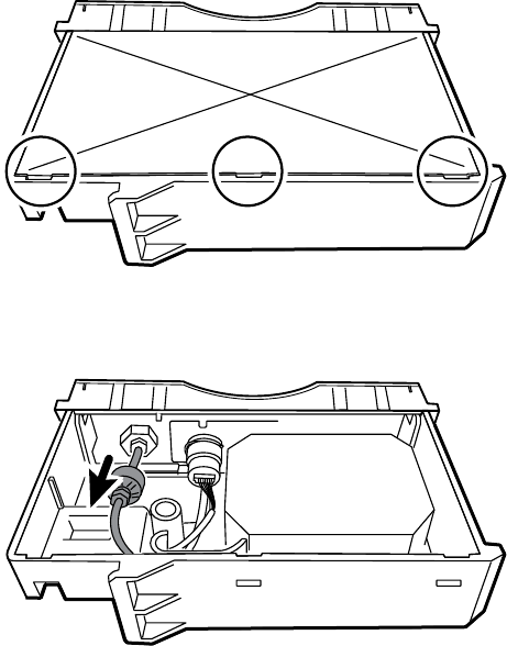
Replace the CO2 module faceplate
Before you begin, remove the following as described in this manual:
• Battery
• Rear housing
• CO2 module
1. Remove the two blank labels securing the clear housing cover to the module housing.
2. Using a slotted screwdriver, release the three plastic clips from the module rear housing, and
remove the clear housing cover.
3. Disconnect the exhaust tube from the exhaust port on the faceplate.
4. Remove the spring clip from the input port, and slide the input port away from the faceplate.
116 Section A

5. Remove the faceplate:
a. Disengage one plastic clip on the module rear housing from the faceplate.
b. Remove the faceplate by pivoting it away from the rear housing.
6. Inspect the new faceplate before installing it:
a. Verify that the spring is attached to the door latch.
b. Verify that the door opens and closes freely.
7. Slide the new faceplate onto the module rear housing until both plastic clips lock in place.
8. Install the input port and spring clip:
a. Slide the input port into the faceplate receptacle until the port is flush with the faceplate.
b. While holding the port in place, install the spring clip over the port and receptacle as
shown in the figure below. The spring clip is secured by pushing on the clip from the
direction of the exhaust fitting towards the faceplate door. Make sure the spring clip is
fully seated.
NOTE Do not reuse the spring clip. Replace the spring clip with the
new one provided in the kit.
Service manual Section A 117

9. Connect the exhaust tube to the exhaust port.
10. Verify that all hoses and wires are routed as shown in the figure below. Also verify that the
tubing is free of kinks.
NOTE The exhaust tube runs along the back of the module and
gradually bends to the exhaust fitting. The inlet tube and wire run
around the molded feature and boss to the large connector.
11. Install the clear housing cover onto the module rear housing, and press the cover into place
until the three plastic clips lock.
12. Apply the two new blank labels to the locations shown in the figure below.
118 Section A

Remove the EarlySense module
Before you begin, remove the following as described in this manual:
• Battery
• Rear housing
1. Disconnect the USB cable from the EarlySense module.
2. Slide the EarlySense module out of the case.
Reassembly notes
Insert the EarlySense module into the housing with the serial number label facing down.
When replacing the EarlySense module or adding an EarlySense module
• Insert the EarlySense module into the housing with the serial number label facing down.
• Connect the USB cable to the EarlySense module.
• When adding an EarlySense module, the bottom housing and SureTemp cover must have
ventilation holes. Use the bottom housing from service kit 105504 and the SureTemp cover
from service kit 103542.
Remove the SpO2 module
Before you begin, remove the following as described in this manual:
• Battery
• Rear housing
• CO2 module or blank faceplate
• EarlySense module (optional)
1. Disconnect the USB cable from the SpO2 module.
2. Remove the USB cable from the retaining clip on the SpO2 module.
Service manual Section A 119

3. Slide the SpO2 module out of the case.
Reassembly notes
• Install the NIBP module (the module closest to the display) before installing the SpO2 module.
• Insert the SpO2 module into the housing with the serial number label facing up.
When replacing the SpO2 module or adding an SpO2 module
CAUTION Ensure that your module has the correct option (Masimo or Nellcor).
• On the back of the SpO2 module, clean the surface to which the retaining clip will be applied
(see figure below) and apply the clip.
• Insert the SpO2 module into the housing with the serial number label facing up.
• Connect the USB cable to the SpO2 module.
• Secure the USB cable to the retaining clip on the SpO2 module.
Remove the NIBP module
Before you begin, remove the following as described in this manual:
• Battery
• Rear housing
• CO2 module or blank faceplate
• EarlySense module (optional)
120 Section A

• SpO2 module or blank faceplate
1. Disconnect the USB cable from the NIBP module.
2. Slide the NIBP module out of the case.
Reassembly notes
• Install the NIBP module (the module closest to the display) before installing the SpO2 and CO2
modules.
• Insert the NIBP module into the housing with the serial number label facing up.
• Connect the USB cable to the NIBP module.
• If originally installed, install the blanking panel by sliding it into the housing.
Remove the bottom housing
Bottom housing for the standard chassis
Service manual Section A 121

No. Item No. Item
10 Screw, plastite #4-20 X 0.500 Torx-pan
head
27 Bottom housing
25 Bottom housing metal chassis 28 Battery connector board
26 Speaker 30 Battery door
Extended bottom housing for the extended chassis
No. Item No. Item
10 Screw, plastite #4-20 X 0.500 Torx-pan
head
30 Battery door
25 Bottom housing metal chassis 73 Extended bottom housing
26 Speaker 74 M4 standoff
28 Battery connector board
Before you begin, remove the following as described in this manual:
• Battery
• Rear housing
• CO2 module or blank faceplate
• EarlySense module
• SpO2 module or blank faceplate
• NIBP module
122 Section A

1. Remove the insert circled in the figure below.
2. If your model has an extended chassis, remove the insert shown below.
3. If your model has a printer, do the following:
a. Remove the drain tube located between the printer and the bottom plate.
b. Disconnect the printer ground wire from the ground lug on the bottom plate.
4. Cut the tie wrap that secures the main harness to the bottom bracket. This tie wrap is located
below the tie wrap on the main harness.
Service manual Section A 123

5. Pull the speaker wire out from behind the bottom bracket and disconnect the speaker cable
(26) from the main harness.
6. Disconnect the following on the battery connector board:
a. The battery power harness from J2.
b. The smart-battery harness from J3.
7. Remove the following screws:
• The bottom housing screw.
• The two screws that secure the bottom housing assembly to the front housing.
8. Remove the bottom housing.
9. Disassemble the bottom housing.
NOTE Disassemble the bottom housing only if you plan to replace
the battery connector board or the speaker. See the instructions for
removing these components later in this section.
Reassembly notes
• When reassembling the bottom housing of an extended chassis, use an 8mm socket and a
Torque driver calibrated for 12.0 inch-pound ±1.0 inch-pound to secure the standoffs (74).
• Plug the speaker cable into the shortest cable of the main harness (the cable closest to the
wire tie). Tuck the cable behind the ground-wire stud. Ensure that the speaker cable is
positioned in the channel.
124 Section A

• If a printer is installed, route the printer ground wire through the channel on the printer
housing.
• Secure the main harness to the bracket on the bottom housing using a tie wrap. Position the
tie wrap just below the tie wrap on the main harness. Use the tie-wrap tool to secure the tie
wrap.
• If your model has an extended chassis, orient the insert so that, when installed, it is flush with
the panel that contains the power button.
When replacing the bottom housing
NOTE The bottom housing, or extended bottom housing, must be replaced by a
Welch Allyn service center to ensure proper labeling.
Remove the speaker
Before you begin, remove the following as described in this manual:
• Battery
• Rear housing
• CO2 module or blank faceplate
• EarlySense module
• SpO2 module or blank faceplate
• NIBP module
• Bottom housing
1. Remove the metal chassis to more easily access the speaker.
Service manual Section A 125

2. Remove the speaker (26) from the bottom housing.
3. Remove any remaining gasket material and clean the surface with 70 percent isopropyl
alcohol.
When replacing the speaker
1. Remove the paper to expose the adhesive on the gasket.
2. Align the holes in the speaker with the pins on the bottom housing and press the speaker into
place.
3. Apply pressure to the outer radius of the speaker to ensure good adhesion with the bottom
housing.
Remove the battery connector board
Before you begin, remove the following as described in this manual:
• Battery
• Rear housing
• CO2 module or blank faceplate
• EarlySense module
• SpO2 module or blank faceplate
• NIBP module
• Bottom housing
Remove the two Torx screws (10) that secure the battery connector board (28) to the bottom
housing using a no. 10 Torx driver.
126 Section A

Remove the top housing
Top housing
No. Item No. Item
14 Screw, M4 X 10 pan head with NYLOC 68 Paper feed roller
31 Handle insert 69 Printer housing
32 Top housing 72 Screw, M2.2X8, Thrdform, PNH, TRX
35 Printer door Not shown Printer door blank
Service manual Section A 127

Housing top extension (extended chassis only)
No. Item No. Item
74 M4 standoff 79 Top housing gasket
75 Housing top extension
Before you begin, remove the following as described in this manual:
• Battery
• Rear housing
• CO2 module or blank faceplate
• EarlySense module
• SpO2 module or blank faceplate
• NIBP module
• Bottom housing
NOTE Do not remove the side panel that contains the power button.
1. If your model has an extended chassis, remove the housing top extension.
a. Use an 8mm socket and driver to remove the two standoffs (74) that secure the housing
top extension (75).
b. Remove the housing top extension.
2. Lay the main harness over the top of the unit to clear the USB cables.
3. Disconnect the power connector on the main harness from J30 on the main board.
128 Section A

4. For models that include the temperature option, disconnect the USB cable connected to the
temperature module from J1 on the main board and free the USB cable from the cable
separator.
NOTE Do not remove the USB cable from the temperature
module unless you plan to replace the module. If you disconnect
the USB cable, the retaining clip must be replaced upon
reassembly.
5. For models that include a printer, unhook the plastic latch to disconnect the USB cable from
the printer.
6. Disconnect the USB cables from the main board.
7. Remove the USB cables and the cable separator.
8. Disconnect and then remove the following:
Service manual Section A 129

a. The fan cable on the main harness from J45 on the main board.
b. The communications power cable on the main harness from J49 on the main board.
c. The battery power harness from J29 on the main board.
d. The smart-battery harness from J34 on the main board.
e. The printer harness from J17 on the main board.
f. The speaker cable on the main harness from J12 on the main board.
NOTE Use extra care when disconnecting J12 to avoid
pulling the connector off the board.
9. Remove the two screws (14) that secure the handle insert and remove the insert.
10. Remove the four Torx screws that secure the handle.
11. Remove the top housing.
Reassembly notes
• Ensure that the printer is installed in the top housing. See the reassembly notes for the printer.
• Before installing the USB cables, install the following:
○ The fan cable on the main harness to J45 on the main board.
○ The communications power cable on the main harness to J49 on the main board, with the
ferrite bead closest to the main board.
○ The battery power harness to J29 on the main board.
○ The smart-battery harness to J34 on the main board.
○ The printer harness to J17 on the main board.
130 Section A

○ The speaker cable on the main harness to J12 on the main board.
NOTE First inspect J12 for bent pins before installing the
speaker cable.
• Install the USB cables based on the type of cable separator you have—6-hole or 11-hole—and
the instructions below.
NOTE The 6-hole separator has been discontinued, but it might
be found in older devices.
USB cable locations—6-hole cable separator
• Place the USB cables in the cable separator.
NOTE If the USB cable was not removed from the temperature
module, leave the J1 position in the figure below vacant until the
cable separator is placed in the case and the other USB cables
have been connected to the main board. When the cable
separator is in the case, connect the USB cable from the
temperature module to J1 on the main board and snap the cable
into the J1 position in the cable separator.
NOTE The cable with right-angle connectors at both ends is in
the J14 position in the figure below.
NOTE If the option is not included, leave the separator position
empty.
• Position each cable to extend approximately 1.5 inches past the separator.
• Place the separator in the unit as shown below.
• Plug the USB cables into the main board as follows:
Service manual Section A 131

No. Item No. Item
J1 Temperature J24 NIBP
J3 Printer J26 COMMS J4
J5 SpO2 J14 COMMS J8
USB cable locations—11-hole cable separator
• Place the USB cables in the cable separator.
NOTE If the USB cable was not removed from the temperature
module, leave the J1 position in the figure below vacant until the
cable separator is placed in the case and the other USB cables
have been connected to the main board. When the cable
separator is in the case, connect the USB cable from the
temperature module to J1 on the main board and snap the cable
into the J1 position in the cable separator.
NOTE The cable with right-angle connectors at both ends is in
the J14 position in the figure below.
NOTE If the option is not included, leave the separator position
empty.
• Position each cable to extend approximately 1.5 inches past the separator.
• Place the separator in the unit as shown below.
132 Section A

• Plug the USB cables into the main board as follows:
• Place the USB cables in the cable separator.
NOTE If the USB cable was not removed from the temperature
module, leave the J1 position in the figure below vacant until the
cable separator is placed in the case and the other USB cables
have been connected to the main board. When the cable
separator is in the case, connect the USB cable from the
temperature module to J1 on the main board and snap the cable
into the J1 position in the cable separator.
NOTE The cable with right-angle connectors at both ends is in
the J14 position in the figure below.
NOTE If the option is not included, leave the separator position
empty.
• Position each cable to extend approximately 1.5 inches past the separator.
• Place the separator in the unit as shown below.
Service manual Section A 133

• Plug the USB cables into the main board as follows:
No. Item No. Item
J1 Temperature J23 SpO2
J2 Printer J26 NIBP
J3 EarlySense J8 COMMS J4
J21 CO2 J14 COMMS J8
J24 CO2
• For models with a temperature module, if you disconnected the USB cable from the
temperature module during disassembly, you must replace the retaining clip. (See the topic
"When replacing the temperature module" for specific instructions.)
• For models with a printer, plug the other end of the USB cable into the printer while pulling
the plastic latch away from the connector. Once the connector is seated, push the plastic latch
over the connector to secure it.
134 Section A

• Verify that the Ethernet cable passes freely through the space between the temperature
housing and the printer board, exiting the case in the space between the top of the
temperature housing and beneath the top housing.
• If the Ethernet cable was removed, re-install it when re-installing the bottom housing.
• When installing the top housing on the chassis, line up the slots on the top housing with the
ends of the horizontal struts on the chassis to ensure proper seating.
• When installing the housing top extension (75), verify that the top housing gasket is in place.
Use an 8mm socket and Torque driver calibrated for 12.0 inch-pound ±1.0 inch-pound to
secure the standoffs (74).
When replacing the top housing
For models without a printer, install the printer door blank as follows:
1. Remove the paper backing from the gasket on the door blank.
2. Install the door blank into the top housing, pressing to secure the door blank to the top
housing.
Remove the printer
Before you begin, remove the following as described in this manual:
• Battery
• Rear housing
• CO2 module or blank faceplate
• EarlySense module
• SpO2 module or blank faceplate
• NIBP module
• Bottom housing
• Top housing
Service manual Section A 135

1. Remove the two Torx screws that secure the printer housing to the top housing.
2. Remove the printer from the top housing:
a. Hold the printer housing while opening the printer door.
b. Separate the printer and printer door from the top housing.
Reassembly notes
1. Verify that the ground wire exits from the side opposite the printer board in the notched area.
2. Place the printer door into the top housing assembly and hold it in place while performing the
next step.
3. Install the printer in the top housing by sliding the tabs into the slots.
4. Snap the printer door shut to hold the printer in place while securing it into the housing with
two screws.
When replacing the printer or adding a printer
• Verify whether the printer housing has a notch, as shown below. If the printer has a notch, you
can use the printer in a standard chassis or an extended chassis. If the printer does not have a
notch, you can use the printer only in a standard chassis.
• If adding a printer, remove the printer door blank. Remove any remaining gasket material and
clean the surface with 70 percent isopropyl alcohol.
1. Separate the door from the printer assembly.
2. Attach the printer ground harness to the printer ground lug.
136 Section A

Service manual Section A 137

Disassemble the front housing
No. Item No. Item
10
Screw, plastite #4-20 X 0.500 Torx-pan head
51
Foam pad
33
Light bar
52
Temperature module
34
Light-bar board
53
Temperature housing
37
Right side panel
54
Probe well seal
38
Power button
55
Horizontal struts
42
Front housing
56
Temperature mounting cover
44
Temperature blanking panel
60
HSG clamp
45
Thermal shield
62
LCD frame
46
Main board
63
Grommet, ear - G411-1
47
Screw, M3 x 5 pan head
64
Shoulder screw, ear G-411-1 metric
138 Section A

No. Item No. Item
48
LCD bezel (1st generation displays)
65
Clamp, cable 3/16 X 3/8 wide X 3/4 long
48b
LCD bezel (2nd generation displays)
66
Washer, M3
49
LCD with touchscreen (1st generation
displays)
67
Left insert
49b
LCD with touchscreen (2nd generation
displays)
71
Temperature connection access cover
50
Foam pad
Remove the light bar
Before you begin, remove the following as described in this manual:
• Battery
• Rear housing
• CO2 module or blank faceplate
• EarlySense module
• SpO2 module or blank faceplate
• NIBP module
• Bottom housing
• Top housing
1. Remove the three screws (10) that secure the horizontal strut (located on the right side when
facing the device from the back) to the front housing.
2. Remove the strut.
3. Remove the tape that secures the light-bar harness to the LCD frame.
Service manual Section A 139

4. Disconnect the light-bar harness from J46 on the main board.
5. Remove the light-bar board (34) and light bar (33) from the front housing.
6. Remove the light-bar board from the light bar.
7. Disconnect the light-bar harness from the light-bar board.
Reassembly notes
• Insert the light-bar board into the light bar as follows:
1. Place the end without the connector into the closed end of the light bar, with the LEDs
facing into the light bar.
2. Ensure that you slide the non-connector end of the light-bar board to the end of the slot
in the light bar.
• Using the end furthest from the ferrite bead, plug the light-bar harness into the light-bar
board.
• Route the light-bar harness as follows:
○ Through the slot in the front housing, underneath the horizontal strut.
○ In the channel and between the top of the housing and the LCD frame standoffs.
• Secure the light-bar harness with tape, making sure that the ferrite bead is between the main
board and the tape.
Remove the temperature module or housing
NOTE These instructions also apply to removing the temperature housing for
models without the temperature option.
NOTE Do not disconnect the USB cable from the temperature module unless you
plan to replace the module and/or the USB cable. Disconnect the USB cable at the
main board when removing the module.
Before you begin, remove the following as described in this manual:
• Battery
• Rear housing
• CO2 module or blank faceplate
• EarlySense module
• SpO2 module or blank faceplate
140 Section A

• NIBP module
• Bottom housing
• Top housing
NOTE You can remove and replace the temperature module without
disconnecting the main harness, battery harnesses, USB cables, or light-bar harness
from the main board.
1. Remove the probe well from the temperature module.
2. Disconnect the power button flex cable from the J6 ZIF locking connector on the main board
and remove the securing tape.
3. Remove the right side panel (37).
4. Remove the two Torx screws (10) from the HSG clamp (60).
5. Remove the two Torx screws (10) that secure the top of the temperature module or empty
housing.
6. Remove the temperature module or empty housing.
NOTE If you are replacing only the temperature module without
replacing the temperature mounting cover, stop here. Install the
replacement module in the reverse order of disassembly procedure.
7. Complete the following steps that apply to your monitor:
• If your monitor has a temperature module, remove the temperature mounting cover:
a. Remove the screw that secures the temperature mounting cover to the front
housing.
Service manual Section A 141

b. Remove the temperature mounting cover (56) from the front housing.
• If your monitor does not have a temperature module, remove the temperature blanking
panel:
a. Remove the two screws that secure the blanking panel to the front housing.
b. Remove the blanking panel (44).
Reassembly notes
• Before installing the temperature module into the front housing, ensure that the probe well
seal is installed with the tab aligned with the slot or notch in the probe well housing.
• Route the power button flex cable up and over the temperature module and plug the cable
into the J6 ZIF locking connector on the main board.
When replacing the temperature module
1. Connect the USB cable to the temperature module.
2. Position the retaining clip on the USB cable against the shoulder of the mini-B connector with
the adhesive pad facing away from the temperature module and toward the bottom.
3. Remove the backing on the retaining clip to expose the adhesive.
4. Rotate the clip on the USB cable to fasten the clip to the temperature module housing.
142 Section A

5. Secure the USB cable with a piece of tape as shown.
When adding a temperature module
1. Follow the instructions to remove the temperature housing, main board, and LCD.
2. Replace the temperature blanking panel (44) with the temperature mounting cover (56).
3. Install the thermal shield (45) on the front housing, aligning the notch on the shield with the
housing.
4. Reinstall the LCD in the reverse order of disassembly.
5. Reinstall the main board in the reverse order of disassembly.
6. Install the probe well seal onto the probe well as described in the reassembly notes for the
temperature module.
7. Insert the temperature module into the front housing aligning the probe well with the access
hole in the front housing.
8. Secure the top of the temperature module to the front housing with two screws included with
the kit.
Service manual Section A 143

9. Place the HSG clamp on the bottom of the temperature module and secure with two screws.
10. Connect the USB cable to the module as described in the instructions for replacing the
temperature module.
Remove the main board
This section includes instructions for 1st generation and 2nd generation displays. Follow the
instructions that apply to your configuration.
NOTE If you are replacing this board, you must have the service tool, Gold
licensed edition, to re-enter the serial number of the monitor and the main board.
NOTE If you are replacing the display, you must replace the bezel, LCD with
touchscreen, and foam pads with the replacement parts in Service kit 106546. The
bezel and foam pads are designed to match the display.
NOTE Different configurations of parts appear in Connex VSM monitors,
depending on the age of the display. Use Configuration A or Configuration B to
identify the components in your device.
Configuration A - 1st generation displays
8x
42
49
50
48
51
47
46
66
64
65
62 63
No. Item No. Item
42 Front housing 51 Foam pad, bottom (and bottom in 2nd
generation models)
46 Main board 62 LCD frame
47 Screw, M3 x 5 pan head 63 Grommet, ear - G411-1
48 LCD bezel 64 Shoulder screw, ear G-411-1 metric
144 Section A

No. Item No. Item
49 LCD with touchscreen 65 Clamp, cable 3/16 X 3/8 wide X 3/4 long
50 Foam pad, bottom (1st generation
displays)
66 Washer, M3
Configuration B - 2nd generation displays
No. Item No. Item
42 Front housing 62 LCD frame
46 Main board 63 Grommet, ear - G411-1
47 Screw, M3 x 5 pan head 64 Shoulder screw, ear G-411-1 metric
48b LCD bezel 65 Clamp, cable 3/16 X 3/8 wide X 3/4 long
49b LCD with touchscreen 66 Washer, M3
51 Foam pads, top and bottom
Before you begin, remove the following as described in this manual:
• Battery
• Rear housing
• CO2 module or blank faceplate
• EarlySense module
• SpO2 module or blank faceplate
Service manual Section A 145

• NIBP module
• Bottom housing
• Top housing
NOTE It is not necessary to remove the temperature module or light bar to
remove the main board or LCD.
1. Disconnect the following on the main board:
a. The power button flex cable from the J6 ZIF locking connector.
b. The light-bar harness from J46.
c. The LCD harness from J19.
d. The LCD flex cable from J48.
CAUTION The solder joint of the LCD connector (J48) is fragile.
When inserting or removing the flex cable, do not stress the
solder joint.
2. Remove the Ethernet cable:
a. Disconnect the Ethernet cable from the Ethernet connector (J11) on the main board.
b. Remove the screw that secures the Ethernet cable P-clamp to the main board.
3. Remove the seven screws that secure the main board to the LCD frame.
146 Section A

4. Remove the main board.
Reassembly notes
• Ensure that the LCD flex cable is not under the main board.
CAUTION The solder joint of the LCD connector (J48) is fragile.
When inserting or removing the flex cable, do not stress the solder
joint.
• Before replacing the MCE board, remove the LCD frame as described in "Remove the LCD."
Once the LCD frame has been removed, install approximately 3 inches of Pro Gaff tape
(M11580) to cover the bottom of the two standoffs as indicated (see "When replacing the LCD
frame"). Do not cover any portion of the large openings. Replace any Pro Gaff tape on the LCD
frame that shows signs of wear or that was removed during reassembly.
• Route the Ethernet cable outside the PEM stud and not underneath the main board.
• Connect the Ethernet cable to the main board:
○ Verify whether your model contains PCBA 407574 revision B, C, or D. Revisions B and C
have no logo on the top surface of the Ethernet port. Revision D has a logo on the top
surface of the Ethernet port. See the figure below.
○ For PCBA 407574 revisions B and C, confirm that the Ethernet cable has a shim on one
connector. Insert the connector with the shim into the Ethernet port.
○ For PCBA 407574 revision D, you can use either an Ethernet cable with a shim or an
Ethernet cable without a shim. Insert the connector into the Ethernet port.
Service manual Section A 147

Revisions B and C Revision D
• When securing the main board, install the screw near J30 after you install the Ethernet cable.
• If the light bar is not installed, install the light-bar harness into the housing, positioning the
ferrite bead near the main board.
When replacing the main board
• When ordering the replacement main board, order the standard license for the model being
serviced. You will receive an authorization code to enter in the service tool to reactivate the
licenses included with the original configuration.
• After reassembling the monitor, use the service tool to provision the monitor as follows:
○ Enter the monitor’s serial number. This can be found on the bottom of the monitor.
○ Restore any previously licensed features by entering the authorization code in the service
tool. Use the authorization codes that accompanied the replacement board, along with
any additional license authorization codes previously installed. Record the device serial
number on the license Authorization Code cards received with the replacement board
and retain for future use. If the license is lost, you can reuse the authorization code on the
same device.
○ Update the host controller software to the current version. If the current version of the
host software is not available after connecting the device to the service tool, contact
Welch Allyn Technical Support.
Remove the LCD
Before you begin, remove the following as described in this manual:
• Battery
• Rear housing
• CO2 module or blank faceplate
• EarlySense module
• SpO2 module or blank faceplate
• NIBP module
• Bottom housing
• Top housing
• Main board
NOTE It is not necessary to remove the temperature module or light bar to
remove the main board or LCD.
148 Section A

1. Disconnect the LCD harness from the LCD. For easier access to the connector, you can slide
the ferrite bead closest to the connector up the harness.
2. Remove the four shoulder screws that secure the LCD frame.
3. Remove the LCD frame.
NOTE Be sure to support the LCD if you are removing it with the
frame. The foam strips on the LCD might cause the LCD to stick to
the frame.
4. Remove the LCD.
Reassembly notes
CAUTION The solder joint of the LCD connector (J48) is fragile. When inserting or
removing the flex cable, do not stress the solder joint.
• Verify that the LCD flex cable feeds through the bezel’s clearance feature. Insert the LCD into
the bezel in the front housing with the LCD flex cable on the lower right as shown. (The image
on the left applies to 1st generation displays while the one on the right applies to 2nd
generation displays.)
1st generation displays 2nd generation displays
• Place the LCD frame over the LCD. Verify that the LCD frame does not cover the LCD flex cable.
Service manual Section A 149

When replacing the LCD frame
• Install a 3-inch strip of Pro Gaff tape on the back of the LCD frame to cover the bottom of the
standoffs. This tape will prevent any small pieces of metal left over from the threading process
from falling into the display where it might cause a short.
• Install the LCD frame with shoulder screws and washers.
• Install a 3-inch strip of Pro Gaff tape over the top part of the LCD harness cutout to protect the
LCD harness from abrasion.
• Install the LCD harness. If it was removed from the frame, use isopropyl alcohol to clean the
area in the scribed boxes where you will mount the harness's ferrite beads. Expose the sticky
backing on the ferrite beads and mount them in the scribed rectangles.
NOTE If you don't place the ferrites correctly in marked areas,
they will obstruct the placement of other components like the
MCE board.
• Attach a piece of tape to the top of the LCD harness to secure it to the frame.
• Attach the LCD frame ground wire to the frame.
•
When replacing the LCD
• Peel the protective sheet from the LCD.
• Verify that the foam strips are installed on the back of the LCD near the top and bottom edges.
On 1st generation displays (see image on the left), the foam strip extends halfway up from the
bottom on both sides of the LCD. On 2nd generation displays, the foam strips are only on the
top and bottom of the LCD (see image on the right).
150 Section A

1st generation displays 2nd generation displays
• Verify that the LCD flex cable feeds through the bezel's clearance feature.
• Add a 1.25-inch strip of tape to the edge of the LCD frame where the LCD flex cable and
ground come around it.
• Insert the LCD into the bezel in the front housing with the LCD flex cable on the lower right as
shown.
• Add a 1.25-inch strip of tape to the edge of the LCD frame, where the harness passes through
to connect to the LCD, to prevent abrasion of the LCD harness.
• When adding the ferrite beads, align the beads with the marks on the LCD frame.
• Add tape to secure the harness to the LCD frame where the harness passes through.
Remove the front housing
Before you begin, remove the following as described in this manual:
• Battery
• Rear housing
• CO2 module or blank faceplate
• EarlySense module
• SpO2 module or blank faceplate
• NIBP module
• Bottom housing
• Top housing
• Light bar
• Temperature module and mounting cover
• Main board
• LCD
To complete disassembly, remove the remaining strut from the front housing.
When replacing the front housing
For models with the temperature option, replace the thermal shield (45).
Service manual Section A 151
152 Section A

Section B
This section applies to devices that meet all of the following criteria:
• manufactured after 11/2017
• MCE hardware version P5 or later
• serial number after 100043244817.
NOTE See "Monitor serial number and model label" in the Appendix to learn how
to determine the manufacture date from the serial number.
This section applies to devices that meet all of the following criteria:
• manufactured after 11/2017
• MCE hardware version P5 or later
• serial number after 100023374817.
NOTE See "Monitor serial number and model label" in the Appendix to learn how
to determine the manufacture date from the serial number.
These devices comply with IEC 60601 3rd edition. Devices built after 12/2018 are 4th-edition
compliant.
NOTE See Customer Service Bulletin 80022414 CSB – CVSM/CIWS IEC 60601 4th
Edition for the exact manufacturing cutoff and start dates as well as the serial
number for the first 4th-edition device.
NOTE If your device does not meet these criteria, see Section A for the correct
disassembly and repair instructions.
If your device is IEC 3rd- or 4th-edition compliant, use only service kits with the "3rd Ed" or "4th Ed"
suffix when replacing the following components:
• MCE (main board)
• LCD
• AC power supply
• AC power supply harness
• printer
• Ethernet cable
• rear housing
• product labels
• power button
• SureTemp module
153

• Masimo SpO2 module
• NIBP module
• EarlySense module
• CO2 module
If your device is IEC 3rd- or 4th-edition compliant, use only service kits with the "3rd Ed" or "4th Ed"
suffix when replacing the following components:
• MCE (main board)
• LCD
• AC power supply
• AC power supply harness
• Ethernet cable
• main housing
• product labels
• SureTemp module
• Masimo SpO2 module
• NIBP module
NOTE For 4th-edition devices, use only 107124* when replacing Nellcor SpO2.
Host software must be 2.40.01 or later.
NOTE Devices that are 4th-edition compliant cannot be downgraded below host
software version 2.41.XX.
Power down the device
You can power down the device as follows: 1) on devices with 2.X software, briefly press the power
button on the housing and then following the onscreen prompts, or 2) on all devices, use onscreen
controls alone.
Option 1. After the device is powered up, briefly press of the power button to open an onscreen
dialog with the following options:
• Power down. Device behavior varies based on the active profile, whether or not patient trend
data is stored, and whether or not patient context is established. While servicing the device,
you need not be concerned about these details. They only matter to clinicians who are
monitoring patients and storing patient data.
• Sleep. The Sleep button clears the display and puts the device into Display power-saving
mode.
• Cancel. The Cancel button dismisses the dialog.
Touch Power down and complete the power-down procedure.
Option 2. To use onscreen controls alone to power down the device, follow these steps:
1. Touch the Settings tab.
2. Touch the Device tab.
3. Touch Power down.
154 Section B
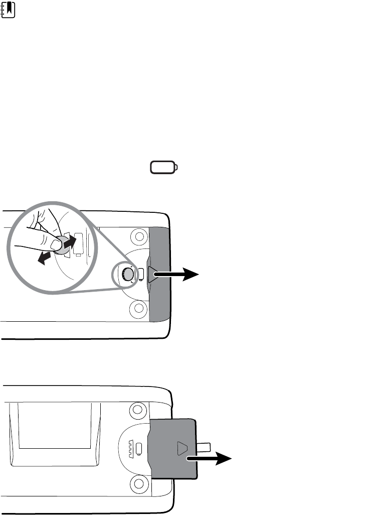
NOTE The next three sections address disassembly and repair steps you can
complete without removing the device from the wall or removing the battery. All
steps presented after “Remove the system from the wall and remove the battery”
require powering down as well as removing the device from the wall and
removing the battery.
Remove the battery
Before removing the battery, power down the monitor as described in this manual and disconnect
the AC power cord.
1. Turn the monitor upside down to access the battery cover.
2. Locate the battery cover, indicated by .
3. Insert a coin into the slot and push to open. Choose a coin that fits comfortably into the slot.
4. Pull the battery out by pulling the battery label, which is visible when you open the battery
cover.
Service manual Section B 155

Remove the rear housing
No. Item No. Item
1 Rear housing 7 Communications door captive screw
2a USB label 4 USB host 8 IEC connector
3a Nurse call label 14 Screw, M4 X 10 pan head with NYLOC
6 Communications door
Before you begin, power down the device, disconnect the AC power cord, and remove the battery
as described in this manual.
1. Lay the monitor face down on the antistatic mat.
2. Loosen the screw (7) to open the communications door (6).
3. Open the communications door (6) to access the rear housing screw.
4. Remove the four rear housing screws (14).
5. Stand the monitor on its feet with the display facing away from you.
6. Pull the top of the rear housing away from the monitor to access the rear housing cable
connections.
7. While supporting the rear housing, disconnect the following from the communications
module:
156 Section B

a. The Ethernet cable from J9.
b. The small USB connector from J4.
c. The large USB connector from J8.
d. The communications power cable from J50.
8. Continuing to support the rear housing, do the following at the power-supply cover:
a. Free the power supply and fan cable from the wire guide on the side of the power-supply
cover.
b. Disconnect the power supply cable from the power supply board at J2.
c. Disconnect the fan cable (A) from the main harness.
d. Disconnect the LCD ground wire from the IEC power harness.
Service manual Section B 157

e. Separate the rear housing (1) from the monitor.
Once the rear housing is removed, choose which part of the monitor to work on:
• Rear housing components. For details, see “Disassemble the rear housing.”
• Main chassis. For details, see “Disassemble the main chassis.”
Reassembly notes
• Route the power cable and fan harness cables in the channel on the side of the power-supply
cover.
• Some communications boards have two large USB connectors. The large USB connector J8 is
the one closest to the mini USB connector J4. For reference, see the communications board
diagram in the appendices.
• When closing the case, verify that no wires are crushed or pinched before securing with
screws. After tightening the screws, examine the seam between the rear housing and the main
chassis to verify that there is no bulging. Bulging indicates that something is preventing the
mating surfaces from seating properly.
When replacing the rear housing
NOTE Use 3rd edition service kit 106840. The rear housing replacement service kit
is assembled with the comms door, ground stud, ground lug plate, IEC connector,
and 3rd edition AC power harness. It is unnecessary to transfer these components
from the old rear housing.
1. Follow the procedures to disassemble the rear housing and remove any components that you
intend to transfer to the replacement housing.
2. Connect the AC power harness to the IEC connector (8). See the reassembly notes for the
power supply.
3. Install the rear housing gasket (15), included in the rear housing service kit, into the slot in the
outer edge of the rear housing. To ease installation, use a small flat-blade screwdriver to assist
in pushing the seal into the channel.
4. Install any components removed from the old rear housing in the reverse order of the
disassembly instructions.
5. After reassembling the rear housing, install the USB client cover (40) as follows:
a. Place the USB client cover on a USB mini B cable with the tape facing out.
b. Peel off the tape to expose the adhesive.
158 Section B

c. Insert the USB cable into the client USB connection, press and remove the cable to adhere
the cover to the rear housing.
6. Install these labels:
• USB label (2a) in the communications door opening.
• Nurse call label (3a) (Serv Kit 106837 CVSM Nurse call label 3rd Ed) over the nurse call
connection.
Remove the communications door
NOTE If the communications door is missing or already removed from the device,
proceed to "When replacing the communications door."
WARNING Personal injury risk. Because removing the door might propel the pin
and spring into the air, wear safety glasses to complete these steps.
Before removing the communications door, power down the monitor, remove the battery, and
remove the rear housing as described.
1. Position the rear housing with the Ethernet connection side down on an antistatic mat.
2. Open the communications door perpendicular to the rear housing.
3. Use a spudger to push the pin upward until the pin clears the hinge.
Service manual Section B 159

4. Carefully remove the door from the rear housing.
When replacing the communications door
WARNING Personal injury risk. Because attaching the door might propel the pin
and spring into the air, wear safety glasses to complete these steps.
1. Insert a spring and two pins into the communications door as shown.
2. With the bottom of the door on the antistatic mat, insert the pin on the right side of the door
into the hinge of the rear housing.
160 Section B

3. Press the pin into the left side of the door and slide the door into the hinge of the rear housing
until it snaps into place.
Service manual Section B 161

Disassemble the rear housing
No. Item No. Item
1 Rear housing 20c Communications board for Newmar radio
(Models 6400, 6500, 6700, and 6800)
8 IEC connector 21a Radio board, Lamarr, 802.11a/b/g
10 Screw, plastite #4-20 X 0.500 Torx-pan head 21b Radio board, Newmar, 802.11a/b/g/n
15 Rear housing gasket (Norprene tubing) 22 Screw, M3 X 0.5, Phillips pan head
16 Antenna board 23 Power supply board
17b AC power harness 24 Antenna mounting foam block
18 Power supply cover 39 Antenna cable
19 Fan 40 USB client cover
20b Communications board (Models 6400, 6500,
6700, and 6800)
97 Screw, M3x0.5x8, Pan Phillips (Small Phillips
screw)
162 Section B

No. Item No. Item
20c Communications board for Newmar radio
(Models 6400, 6500, 6700, and 6800)
98 Nomex ESD shield, CVSM power supply (4th
edition only)
Service manual Section B 163
Remove the communications board
Before you begin, remove the following as described in this manual:
• Battery
• Rear housing
1. Lay the rear housing on its back on the antistatic mat.
2. Remove the four Torx screws (10) that secure the communications board (20a or 20b) to the
rear housing.
3. Remove the communications board by doing the following:
a. Lift the inside edge of the board until the USB connector clears the wire channel on the
power-supply cover.
b. Slide the board slightly toward the power supply and lift until the board contacts the wire
channel on the power-supply cover.
c. Lift the outside edge of the board until the side connectors clear the rear housing.
d. For monitors with a radio: rotate the board (without pulling on the antenna cable) slightly
counter-clockwise, pivoting on the upper left-hand corner. Turn the board over and set it
down outside the top of the case.
4. If replacing the communications board, remove the radio board (21) as described in “Remove
the radio board and antenna.”
Reassembly notes
• If the radio board was removed, reinstall it before reinstalling the communications board.
• To install the communications board, do the following:
1. Position the board over the standoffs with the inside edge of the board under the wire
channel on the power-supply cover until the outer edge drops into the rear housing.
2. Align the mini-USB external connector with the opening in the side of the rear housing.
3. Slide the mini-USB connector into the opening until the board rests on the standoffs.
When replacing the communications board
Install the radio board on the new communications board before installing the communications
board on the rear housing.
164 Section B

Remove the radio board and antenna
CAUTION Do not remove the radio antenna from the rear housing unless
replacing the radio and antenna or the rear housing.
Before you begin, remove the following as described in this manual:
• Battery
• Rear housing
• Communications board
1. If the monitor has a radio:
a. Turn the communications board over to access the radio board, taking care to avoid
straining the antenna cable.
b. If the original Lamarr radio (a/b/g band) is installed, remove the four small Phillips
(machine) screws securing the radio board to the communications board, as shown on
the left. If the Newmar radio (a/b/g/n band) is installed, remove the three small Phillips
(machine) screws securing the radio board to the communications board, as shown on
the right.
c. Hold the communications board with one hand while grasping the radio board at the
opposite end from the antenna connection and pull the radio board away from the
communications board.
2. (Perform this step only if you are replacing the radio or antenna.) Disconnect the radio antenna
cable from the radio board.
3. Remove the four Torx screws (10) securing the power-supply cover.
4. Remove the power-supply cover (18).
5. Use a soft tool such as a spudger to separate the foam block (24) from the inside of the rear
housing.
Service manual Section B 165

Reassembly notes
Route the antenna cable in the channel located at the top of the rear housing.
When replacing the radio board and antenna
1. If the antenna is removed, clean the rear housing and mounting surface with isopropyl alcohol.
2. The following illustration shows both Lamarr and Newmar radio and antenna boards. Attach
the antenna cable to terminal G on the radio board. Attach the other end of the cable to the
antenna on terminal PG.
3. Peel the backing off the foam block (24) and affix the foam block to the rear housing.
4. Expose the adhesive on the foam block. Mount the antenna (16) on the foam block with the
antenna cable (39) oriented under the board and in the wire channel above the power supply.
5. Route the antenna cable in the channel located at the top of the rear housing.
166 Section B

Remove the fan
Before you begin, remove the following as described in this manual:
• Battery
• Rear housing
1. Press the flanges on the sides of the fan harness connector and separate the fan connector
from the power-supply cover (18).
2. Depress the tab on the power-supply cover and slide the fan (19) over the tab and out of the
housing.
Reassembly notes
CAUTION Ensure that the fan is properly oriented. Air must flow toward the
power supply.
NOTE If the fan is dirty, use canned air to remove dust. Do not bend the fan
blades or otherwise damage the fan. If the fan is noisy and cleaning does not
reduce the noise, replace the fan.
• With the label facing down, slide the fan into the housing on top of the power-supply cover
until the tab on the cover holds it in place.
• Clip the fan harness into the power-supply cover so that the connector is oriented toward the
fan, as shown in the following figure.
Service manual Section B 167

Remove the power supply
Before you begin, remove the following as described in this manual:
• Battery
• Rear housing
1. Remove the four Torx screws (10) securing the power-supply cover.
2. Remove the power-supply cover (18).
3. Disconnect the following from the power supply:
• The (green) ground cable
• The AC power harness (17b)
NOTE See "Remove the AC power harness" for instructions.
4. Remove the power supply and Nomex shield if present.
168 Section B

Remove the AC power harness
NOTE Do not disconnect the AC power harness from the IEC connector unless
you are replacing it. Once you disconnect the AC power harness, you cannot reuse
it.
Before you begin, remove the following as described in this manual:
• Battery
• Rear housing
• Power supply
1. Disconnect the AC power harness from the IEC connector.
2. Remove the metal grounding plate from the housing rib.
3. Remove the two screws securing the ground stud assembly to the rear housing.
4. Remove the ground stud AC power harness assembly.
Reassembly notes
When replacing the rear case or AC power harness, route the wiring as follows:
• Connect blue to neutral (N), green to ground (GND), and brown to line (L).
Service manual Section B 169

NOTE The power supply harness to IEC connector is rated for a single connection.
Replace the power supply harness if it has been disconnected from the IEC
connector.
• Ensure that the grommet on the AC power harness is in the slot in the power supply cover.
• Place ferrite on the AC power harness assembly into the molded feature on the back housing
and then check the following details:
○ Ensure that the edge of the ferrite is inside the edge of the molded feature.
○ Ensure that the wires on the power supply wire harness ferrite are on the sides of the
ferrite.
○ Confirm that the wires to the power supply and the LCD ground wire pass over the top of
the wires to the ferrite.
○ Confirm that the power cables are not pinched by the power supply cover.
• When replacing the power supply cover, ensure that the antenna cable is routed in the
channel located at the top of the rear housing.
170 Section B
• When replacing the power supply, if the a Nomex ESD shield was installed, inspect the ESD
shield and replace as needed. Replace the shield if you see any degradation of the material.
Service manual Section B 171

Disassemble the main chassis
Disassembly and reassembly procedures are the same for the standard chassis and extended
chassis, unless otherwise noted.
Configuration options
Standard chassis (left side)
Supports a maximum of two modules
Extended chassis (left side)
Supports a maximum of three modules
Components (back to front):
SpO2, NIBP
Blank, NIBP (6300, 6400, and 6500 only)
Components (back to front):
CO2, SpO2, NIBP
Blank, SpO2, NIBP
172 Section B

Extended chassis (right side) Supports a maximum of one module
NOTE The standard chassis is the same as extended chassis minus space for an EarlySense
module, so it is not presented here.
Components (front to back):
Power button, EarlySense, Ethernet RJ-45, USB client, Nurse call
Power button, Blank, Ethernet RJ-45, USB client, Nurse call
NOTE Monitors configured with RRa, SpHb, or CO2 cannot be configured with EarlySense.
NOTE Ethernet RJ-45 provides a hardwired connection to the computer network. USB
client provides a connection to an external computer for testing and software upgrades.
Nurse call provides a connection to the hospital nurse call system.
Service manual Section B 173

Main chassis exploded view
More detailed views of main chassis components and tables identifying specific parts appear later
in this section preceding the associated disassembly and repair instructions.
No. Item No. Item
10
Screw, plastite #4-20 X 0.500 Torx-pan head
54
Probe well seal
14
Screw, M4 X 10 pan head with NYLOC
55
Horizontal struts
25
Bottom housing metal chassis
56
Temperature mounting cover
174 Section B

No. Item No. Item
26
Speaker
60
HSG clamp
27
Bottom housing
62b
LCD frame
28
Battery connector board
63
Grommet, ear - G411-1
30
Battery door
64
Shoulder screw, ear G-411-1 metric
31
Handle insert
67
Left insert
32
Top housing
68
Paper-feed roller
33
Light bar
69
Printer
34
Light-bar board
71
Temperature connection access cover
35
Printer door
72
Screw, M2.2X8, THRDFORM, PNH, TRX
37
Right side panel
73
Extended bottom housing
38
Power button and flex cable
74
M4 standoff
42
Front housing
75
Housing top extension
44
Temperature blanking panel
79
Top housing gasket
45
Thermal shield
83
CO2 module assembly
46b
Main board
84
EarlySense module assembly
47
Screw, M3 x 5 pan head
85
Blank faceplate
48b
LCD bezel
86
SpO2 module assembly
49c
LCD with touchscreen
87
USB cable retaining clip
51
Foam pad
88
NIBP module assembly
52
Temperature module
95
LCD frame ground wire
Service manual Section B 175

No. Item No. Item
53
Temperature housing
96
Lock washer
Remove the CO2 module
Before you begin, remove the following as described in this manual:
• Battery
• Rear housing
1. Disconnect the two USB cables from the CO2 module.
2. Slide the CO2 module out of the case.
Reassembly notes
• Do the following before installing the CO2 module:
○ Install the NIBP module (the module closest to the display).
○ Install the SpO2 module.
• Insert the CO2 module into the housing with the serial number label facing up.
• Connect the two USB cables to the CO2 module.
NOTE You may connect the CO2 USB cables in any order in either
CO2 FSS USB socket.
Replace the CO2 module faceplate
Before you begin, remove the following as described in this manual:
176 Section B

• Battery
• Rear housing
• CO2 module
1. Remove the two blank labels securing the clear housing cover to the module housing.
2. Using a slotted screwdriver, release the three plastic clips from the module rear housing, and
remove the clear housing cover.
3. Disconnect the exhaust tube from the exhaust port on the faceplate.
4. Remove the spring clip from the input port, and slide the input port away from the faceplate.
5. Remove the faceplate:
a. Disengage one plastic clip on the module rear housing from the faceplate.
Service manual Section B 177

b. Remove the faceplate by pivoting it away from the rear housing.
6. Inspect the new faceplate before installing it:
a. Verify that the spring is attached to the door latch.
b. Verify that the door opens and closes freely.
7. Slide the new faceplate onto the module rear housing until both plastic clips lock in place.
8. Install the input port and spring clip:
a. Slide the input port into the faceplate receptacle until the port is flush with the faceplate.
b. While holding the port in place, install the spring clip over the port and receptacle as
shown in the figure below. The spring clip is secured by pushing on the clip from the
direction of the exhaust fitting towards the faceplate door. Make sure the spring clip is
fully seated.
NOTE Do not reuse the spring clip. Replace the spring clip with the
new one provided in the kit.
9. Connect the exhaust tube to the exhaust port.
10. Verify that all hoses and wires are routed as shown in the figure below. Also verify that the
tubing is free of kinks.
178 Section B

NOTE The exhaust tube runs along the back of the module and
gradually bends to the exhaust fitting. The inlet tube and wire run
around the molded feature and boss to the large connector.
11. Install the clear housing cover onto the module rear housing, and press the cover into place
until the three plastic clips lock.
12. Apply the two new blank labels to the locations shown in the figure below.
Remove the EarlySense module
Before you begin, remove the following as described in this manual:
• Battery
• Rear housing
1. Disconnect the USB cable from the EarlySense module.
Service manual Section B 179

2. Slide the EarlySense module out of the case.
Reassembly notes
Insert the EarlySense module into the housing with the serial number label facing down.
When replacing the EarlySense module or adding an EarlySense module
Use 106838 SK CVSM Early Sense Module 3rd Ed.
• Insert the EarlySense module into the housing with the serial number label facing down.
• Connect the USB cable to the EarlySense module.
• When adding an EarlySense module, the bottom housing and SureTemp cover must have
ventilation holes. Use the bottom housing from service kit 105504 and the SureTemp cover
from service kit 103542.
Remove the SpO2 module
Before you begin, remove the following as described in this manual:
• Battery
• Rear housing
• CO2 module or blank faceplate
• EarlySense module (optional)
1. Disconnect the USB cable from the SpO2 module.
2. Remove the USB cable from the retaining clip on the SpO2 module.
3. Slide the SpO2 module out of the case.
Reassembly notes
• Install the NIBP module (the module closest to the display) before installing the SpO2 module.
180 Section B

• Insert the SpO2 module into the housing with the serial number label facing up.
When replacing the SpO2 module or adding an SpO2 module
CAUTION Ensure that your module has the correct option (Masimo or Nellcor).
• On the back of the SpO2 module, clean the surface to which the retaining clip will be applied
(see figure below) and apply the clip.
• Insert the SpO2 module into the housing with the serial number label facing up.
• Connect the USB cable to the SpO2 module.
• Secure the USB cable to the retaining clip on the SpO2 module.
Remove the NIBP module
Before you begin, remove the following as described in this manual:
• Battery
• Rear housing
• CO2 module or blank faceplate
• EarlySense module (optional)
• SpO2 module or blank faceplate
1. Disconnect the USB cable from the NIBP module.
2. Slide the NIBP module out of the case.
Service manual Section B 181

Reassembly notes
• Install the NIBP module (the module closest to the display) before installing the SpO2 and CO2
modules.
• Insert the NIBP module into the housing with the serial number label facing up.
• Connect the USB cable to the NIBP module.
• If originally installed, install the blanking panel by sliding it into the housing.
Remove the bottom housing
Bottom housing for the standard chassis
No. Item No. Item
10 Screw, plastite #4-20 X 0.500 Torx-pan
head
30 Battery door
25 Bottom housing metal chassis 95 LCD frame ground wire
27 Bottom housing 96 Lock washer
28 Battery connector board
Extended bottom housing for the extended chassis
182 Section B

No. Item No. Item
10 Screw, plastite #4-20 X 0.500 Torx-pan
head
73 Extended bottom housing
25 Bottom housing metal chassis 74 M4 standoff
26 Speaker 95 LCD frame ground wire
28 Battery connector board 96 Lock washer
30 Battery door
Before you begin, remove the following as described in this manual:
• Battery
• Rear housing
• CO2 module or blank faceplate
• EarlySense module
• SpO2 module or blank faceplate
• NIBP module
1. Remove the insert circled in the figure below.
Service manual Section B 183

2. If your model has an extended chassis, remove the insert shown below.
3. If your model has a printer, do the following:
a. Remove the drain tube located between the printer and the bottom plate.
b. Disconnect the printer ground wire from the ground lug on the bottom plate.
184 Section B

4. Cut the tie wrap that secures the main harness to the bottom bracket. This tie wrap is located
below the tie wrap on the main harness.
5. Pull the speaker wire out from behind the bottom bracket and disconnect the speaker cable
(26) from the main harness.
6. Disconnect the following on the battery connector board:
a. The battery power harness from J2.
b. The smart-battery harness from J3.
7. Remove the Pro Gaff tape securing the Ethernet cable and the LCD ground wire to the metal
chassis.
NOTE Observe the locations of the Pro Gaff tape so that you can
replace it properly during reassembly.
Service manual Section B 185

8. Remove the following screws:
• The bottom housing screw.
• The two screws that secure the bottom housing assembly to the front housing.
9. Remove the bottom housing.
a. Pivot the bottom housing along the edge shared with the front housing and lay it on the
work bench.
b. Remove the screw securing the LCD frame ground wire to the LCD frame.
186 Section B

10. Disassemble the bottom housing:
NOTE Disassemble the bottom housing only if you plan to
replace the battery connector board or the speaker. See the
instructions for removing these components later in this section.
Reassembly notes
• When reassembling the bottom housing of an extended chassis, use an 8mm socket and a
Torque driver calibrated for 12.0 inch-pound ±1.0 inch-pound to secure the standoffs (74).
• Plug the speaker cable into the shortest cable of the main harness (the cable closest to the
wire tie). Tuck the cable behind the ground-wire stud. Ensure that the speaker cable is
positioned in the channel.
• If a printer is installed, route the printer ground wire through the channel on the printer
housing and wrap the printer ground cable once around the printer drain tube.
• Tie wrap the smart harness, battery, and speaker wires together.
Service manual Section B 187

• Route the main harness wires over the USB cables and cable separator.
• Replace the Pro Gaff tape securing the LCD ground wire to the battery frame. Tape the ground
wire to the battery frame between the center rib and the holes on the right end.
• If the Ethernet cable was removed, connect it to the MCE board. Route the Ethernet cable from
the MCE diagonally across the bottom housing metal chassis to the metal bracket above the
battery board and use a 2'' piece of Pro Gaff tape to tape it to the edge of the metal chassis.
Bend the Ethernet cable to parallel the right side of the SureTemp housing, passing over the
power button flex cable and under the SureTemp USB cable to the tie wrap anchor on the
SureTemp housing's upper right side.
188 Section B

• Secure the main harness to the bracket on the bottom housing. Position the Ethernet cable
behind the bracket and secure both with a tie wrap. Use the tie-wrap tool to secure the tie
wrap.
• If the tie wrap securing the Ethernet cable to the tie wrap anchor on the SureTemp housing
was removed, use a tie wrap to secure the Ethernet cable to the tie wrap anchor. As noted
previously, route the Ethernet cable over the power button flex cable and under the SureTemp
USB cable to the tie wrap anchor.
When replacing the bottom housing
NOTE The bottom housing, or extended bottom housing, must be replaced by a
Welch Allyn service center to ensure proper labeling.
Remove the speaker
Before you begin, remove the following as described in this manual:
• Battery
• Rear housing
• CO2 module or blank faceplate
• EarlySense module
• SpO2 module or blank faceplate
• NIBP module
• Bottom housing
1. Remove the metal chassis to more easily access the speaker.
2. Remove the speaker (26) from the bottom housing.
Service manual Section B 189

3. Remove any remaining gasket material and clean the surface with 70 percent isopropyl
alcohol.
When replacing the speaker
1. Remove the paper to expose the adhesive on the gasket.
2. Align the holes in the speaker with the pins on the bottom housing and press the speaker into
place.
3. Apply pressure to the outer radius of the speaker to ensure good adhesion with the bottom
housing.
Remove the battery connector board
Before you begin, remove the following as described in this manual:
• Battery
• Rear housing
• CO2 module or blank faceplate
• EarlySense module
• SpO2 module or blank faceplate
• NIBP module
• Bottom housing
Remove the two Torx screws (10) that secure the battery connector board (28) to the bottom
housing using a no. 10 Torx driver.
190 Section B

Remove the top housing
Top housing
No. Item No. Item
14 Screw, M4 X 10 pan head with NYLOC 68 Paper feed roller
31 Handle insert 69 Printer housing
32 Top housing 72 Screw, M2.2X8, Thrdform, PNH, TRX
35 Printer door Not shown Printer door blank
Service manual Section B 191

Housing top extension (extended chassis only)
No. Item No. Item
74 M4 standoff 79 Top housing gasket
75 Housing top extension
Before you begin, remove the following as described in this manual:
• Battery
• Rear housing
• CO2 module or blank faceplate
• EarlySense module
• SpO2 module or blank faceplate
• NIBP module
• Bottom housing
NOTE Do not remove the side panel that contains the power button.
1. If your model has an extended chassis, remove the housing top extension.
a. Use an 8mm socket and driver to remove the two standoffs (74) that secure the housing
top extension (75).
b. Remove the housing top extension.
2. Cut the tie wrap securing the smart battery harness to the main harness.
192 Section B

3. Lay the main harness over the top of the unit to clear the USB cables.
4. Disconnect the power connector on the main harness from J30 on the main board.
5. For models that include the temperature option, disconnect the USB cable connected to the
temperature module from J1 on the main board and free the USB cable from the cable
separator.
NOTE Do not remove the USB cable from the temperature
module unless you plan to replace the module. If you disconnect
the USB cable, the retaining clip must be replaced upon
reassembly.
6. For models that include a printer, unhook the plastic latch to disconnect the USB cable from
the printer.
7. Disconnect the USB cables from the main board.
8. Remove the USB cables and the cable separator.
Service manual Section B 193

9. Disconnect and then remove the following:
a. The fan cable on the main harness from J45 on the main board.
b. The communications power cable on the main harness from J49 on the main board.
c. The battery power harness from J29 on the main board.
d. The smart-battery harness from J34 on the main board.
e. The printer harness from J17 on the main board.
f. The speaker cable on the main harness from J12 on the main board.
NOTE Use extra care when disconnecting J12 to avoid
pulling the connector off the board.
10. Remove the two screws (14) that secure the handle insert and remove the insert.
11. Remove the four Torx screws that secure the handle.
12. Remove the Pro Gaff tape securing the printer harness (if present) and light bar harness to the
LCD frame. Note the location of the Pro Gaff tape for placement during reassembly.
194 Section B

13. Remove the top housing.
Reassembly notes
• Ensure that the printer is installed in the top housing. See the reassembly notes for the printer.
• For devices equipped with a printer, position the top housing close to the main chassis,
connect the printer harness, and secure both the light bar harness and the printer harness to
the LCD frame with approximately 2 inches of Pro Gaff tape.
• Before installing the USB cables, install the following:
○ The fan cable on the main harness to J45 on the main board.
○ The communications power cable on the main harness to J49 on the main board, with the
ferrite bead closest to the main board.
○ The battery power harness to J29 on the main board.
○ The smart-battery harness to J34 on the main board.
○ The printer harness to J17 on the main board.
○ The speaker cable on the main harness to J12 on the main board.
NOTE First inspect J12 for bent pins before installing the
speaker cable.
• Install the USB cables based on the instructions below.
USB cable locations—9-hole cable separator
• Place the USB cables in the cable separator.
NOTE If the USB cable was not removed from the temperature
module, leave the J1 position in the figure below vacant until the
cable separator is placed in the case and the other USB cables
have been connected to the main board. When the cable
separator is in the case, connect the USB cable from the
temperature module to J1 on the main board and snap the cable
into the J1 position in the cable separator.
NOTE The cable with right-angle connectors at both ends is in
the J14 position in the figure below.
NOTE If the option is not included, leave the separator position
empty.
• Position each cable to extend approximately 2 inches past the separator.
Service manual Section B 195

• When positioning the separator in the device, place the feet in the marked areas of the MCE
board as shown.
J1 J2 J24J21 J23 J8 J14J26J3
• Plug the USB cables into the main board as follows:
No. Item No. Item
J1 Temperature J23 SpO2
J2 Printer J26 NIBP
J3 EarlySense J8 COMMS J4
J21 CO2 J14 COMMS J8
J24 CO2
• For models with a temperature module, if you disconnected the USB cable from the
temperature module during disassembly, you must replace the retaining clip. (See the topic
"When replacing the temperature module" for specific instructions.)
• For models with a printer, plug the other end of the USB cable into the printer while pulling
the plastic latch away from the connector. Once the connector is seated, push the plastic latch
over the connector to secure it.
196 Section B

• Verify that the Ethernet cable passes freely through the space between the temperature
housing and the printer board, exiting the case in the space between the top of the
temperature housing and beneath the top housing.
• If the Ethernet cable was removed, re-install it when re-installing the bottom housing.
• When installing the top housing on the chassis, line up the slots on the top housing with the
ends of the horizontal struts on the chassis to ensure proper seating.
• When installing the housing top extension (75), verify that the top housing gasket is in place.
Use an 8mm socket and Torque driver calibrated for 12.0 inch-pound ±1.0 inch-pound to
secure the standoffs (74).
When replacing the top housing
For models without a printer, install the printer door blank as follows:
1. Remove the paper backing from the gasket on the door blank.
2. Install the door blank into the top housing, pressing to secure the door blank to the top
housing.
Remove the printer
Before you begin, remove the following as described in this manual:
• Battery
• Rear housing
• CO2 module or blank faceplate
• EarlySense module
• SpO2 module or blank faceplate
• NIBP module
• Bottom housing
• Top housing
Service manual Section B 197

1. Remove the two Torx screws that secure the printer housing to the top housing.
2. Remove the printer from the top housing:
a. Hold the printer housing while opening the printer door.
b. Separate the printer and printer door from the top housing.
Reassembly notes
1. Verify that the ground wire exits from the side opposite the printer board in the notched area.
2. Place the printer door into the top housing assembly and hold it in place while performing the
next step.
3. Install the printer in the top housing by sliding the tabs into the slots.
4. Snap the printer door shut to hold the printer in place while securing it into the housing with
two screws.
5. Connect the printer ground wire to the bottom housing. (See the bottom housing reassembly
notes.)
When replacing the printer or adding a printer
• If adding a printer, remove the printer door blank. Remove any remaining gasket material and
clean the surface with 70 percent isopropyl alcohol.
1. Separate the door from the printer assembly.
2. Follow the reassembly notes above to install the printer.
3. Connect the printer ground wire to the bottom housing. (See the bottom housing reassembly
notes.)
198 Section B

Disassemble the front housing
No. Item No. Item
10
Screw, plastite #4-20 X 0.500 Torx-pan head
52
Temperature module
33
Light bar
53
Temperature housing
34
Light-bar board
54
Probe well seal
37
Right side panel
55
Horizontal struts
38
Power button
56
Temperature mounting cover
42
Front housing
60
HSG clamp
44
Temperature blanking panel
62b
LCD frame
45
Thermal shield
63
Grommet, ear - G411-1
46b
Main board
64
Shoulder screw, ear G-411-1 metric
47
Screw, M3 x 5 pan head
67
Left insert
Service manual Section B 199

No. Item No. Item
48b
LCD bezel
71
Temperature connection access cover
49c
LCD with touchscreen
95
LCD frame ground wire
51
Foam pad, top and bottom
96
Lock washer
Remove the light bar
Before you begin, remove the following as described in this manual:
• Battery
• Rear housing
• CO2 module or blank faceplate
• EarlySense module
• SpO2 module or blank faceplate
• NIBP module
• Bottom housing
• Top housing
1. Remove the three screws (10) that secure the horizontal strut (located on the right side when
facing the device from the back) to the front housing.
2. Remove the strut.
3. Remove the tape that secures the light-bar harness to the LCD frame.
200 Section B

4. Disconnect the light-bar harness from J46 on the main board.
5. Remove the light-bar board (34) and light bar (33) from the front housing.
6. Remove the light-bar board from the light bar.
7. Disconnect the light-bar harness from the light-bar board.
Reassembly notes
• Insert the light-bar board into the light bar as follows:
1. Place the end without the connector into the closed end of the light bar, with the LEDs
facing into the light bar.
2. Ensure that you slide the non-connector end of the light-bar board to the end of the slot
in the light bar.
• Using the end furthest from the ferrite bead, plug the light-bar harness into the light-bar
board.
• Route the light-bar harness as follows:
○ Through the slot in the front housing, underneath the horizontal strut.
○ In the channel and between the top of the housing and the LCD frame standoffs.
• Secure the light-bar harness with tape, making sure that the ferrite bead is between the main
board and the tape.
Remove the temperature module or housing
NOTE These instructions also apply to removing the temperature housing for
models without the temperature option.
NOTE Do not disconnect the USB cable from the temperature module unless you
plan to replace the module and/or the USB cable. Disconnect the USB cable at the
main board when removing the module.
Before you begin, remove the following as described in this manual:
• Battery
• Rear housing
• CO2 module or blank faceplate
• EarlySense module
• SpO2 module or blank faceplate
Service manual Section B 201

• NIBP module
• Bottom housing
• Top housing
NOTE You can remove and replace the temperature module without
disconnecting the main harness, battery harnesses, USB cables, or light-bar harness
from the main board.
1. Remove the probe well from the temperature module.
NOTE Disconnect the Ethernet cable from the MCE board or cut
the wire tie securing the Ethernet cable to the SureTemp housing.
2. Disconnect the power button flex cable from the J6 ZIF locking connector on the main board
and remove the securing tape.
3. Remove the right side panel (37).
4. Remove the two Torx screws (10) from the HSG clamp (60).
202 Section B

5. Remove the two Torx screws (10) that secure the top of the temperature module or empty
housing.
6. Remove the temperature module or empty housing.
NOTE If you are replacing only the temperature module without
replacing the temperature mounting cover, stop here. Install the
replacement module in the reverse order of disassembly procedure.
7. Complete the following steps that apply to your monitor:
• If your monitor has a temperature module, remove the temperature mounting cover:
a. Remove the screw that secures the temperature mounting cover to the front
housing.
b. Remove the temperature mounting cover (56) from the front housing.
• If your monitor does not have a temperature module, remove the temperature blanking
panel:
a. Remove the two screws that secure the blanking panel to the front housing.
b. Remove the blanking panel (44).
Reassembly notes
• Before installing the temperature module into the front housing, ensure that the probe well
seal is installed with the tab aligned with the slot or notch in the probe well housing.
Service manual Section B 203

• Route the power button flex cable up and over the temperature module and plug the cable
into the J6 ZIF locking connector on the main board.
When replacing or adding a temperature module
Follow these instructions when replacing temperature modules and when installing them in the
device for the first time.
1. Prepare the temperature module housing: Attach the cable tie mount (113P463) with a .75-
inch square foam strip (78P567) to the SureTemp housing near the top corner of the housing
as shown.
2. Connect the USB cable to the temperature module.
3. Position the retaining clip on the USB cable against the shoulder of the mini-B connector with
the adhesive pad facing away from the temperature module and toward the bottom.
4. Remove the backing on the retaining clip to expose the adhesive.
5. Rotate the clip on the USB cable to fasten the clip to the temperature module housing.
204 Section B

6. Secure the USB cable with a piece of tape as shown.
When adding a temperature module
In addition to completing the steps in the previous section, follow these instructions when
installing a temperature module in the device for the first time.
1. Follow the instructions to remove the temperature housing, main board, and LCD.
2. Replace the temperature blanking panel (44) with the temperature mounting cover (56).
3. Install the thermal shield (45) on the front housing, aligning the notch on the shield with the
housing.
4. Reinstall the LCD in the reverse order of disassembly.
5. Reinstall the main board in the reverse order of disassembly.
6. Install the probe well seal onto the probe well as described in the reassembly notes for the
temperature module.
7. Insert the temperature module into the front housing aligning the probe well with the access
hole in the front housing.
Service manual Section B 205

8. Secure the top of the temperature module to the front housing with two screws included with
the kit.
9. Place the HSG clamp on the bottom of the temperature module and secure with two screws.
10. Connect the USB cable to the module as described in the instructions for replacing the
temperature module.
Remove the main board
NOTE If you are replacing this board, you must have the service tool, Gold
licensed edition, to re-enter the serial number of the monitor and the main board.
NOTE If you are replacing the display, you must replace the bezel, LCD with
touchscreen, and foam pads with the replacement parts in Service kit 106825. The
bezel and foam pads are designed to match the display.
No. Item No. Item
10 Screw, plastite #4-20 X 0.500 Torx-pan
head
51 Foam pads, top and bottom
42 Front housing 62b LCD frame
46b Main board 63 Grommet, ear - G411-1
47 Screw, M3 x 5 pan head 64 Shoulder screw, ear G-411-1 metric
48b LCD bezel 95 Ground wire
49c LCD with touchscreen 96 Lock washer
Before you begin, remove the following as described in this manual:
206 Section B

• Battery
• Rear housing
• CO2 module or blank faceplate
• EarlySense module
• SpO2 module or blank faceplate
• NIBP module
• Bottom housing
• Top housing
NOTE It is not necessary to remove the temperature module or light bar to
remove the main board or LCD.
1. Disconnect the following on the main board:
a. The power button flex cable from the J6 ZIF locking connector.
b. The light-bar harness from J46.
c. The LCD harness from J19.
d. The LCD flex cable from J48.
CAUTION The solder joint of the LCD connector (J48) is fragile.
When inserting or removing the flex cable, do not stress the
solder joint.
2. Disconnect the Ethernet cable from the Ethernet connector (J11) on the main board and
remove it.
Service manual Section B 207

3. Remove the eight screws that secure the main board to the LCD frame.
4. Remove the main board.
Reassembly notes
• Ensure that the LCD flex cable is not under the main board.
CAUTION The solder joint of the LCD connector (J48) is fragile.
When inserting or removing the flex cable, do not stress the solder
joint.
• Remove the LCD frame as described in "Remove the LCD." Once the LCD frame has been
removed, install approximately 3 inches of Pro Gaff tape (M11580) to cover the bottom of the
two standoffs as indicated (see “When replacing the LCD frame”). Do not cover any portion of
the large openings. Replace any Pro Gaff tape on the LCD frame that shows signs of wear or
that was removed during reassembly.
• Re-install the Ethernet cable (see Reassembly notes for the bottom housing).
• If the light bar is not installed, install the light-bar harness into the housing, positioning the
ferrite bead near the main board.
When replacing the main board
• Use service kit 1068939 on IEC 60601 3rd edition-compliant devices.
• When ordering the replacement main board, order the standard license for the model being
serviced. You will receive an authorization code to enter in the service tool to reactivate the
licenses included with the original configuration.
• After reassembling the monitor, use the service tool to provision the monitor as follows:
○ Enter the monitor’s serial number. This can be found on the bottom of the monitor.
○ Restore any previously licensed features by entering the authorization code in the service
tool. Use the authorization codes that accompanied the replacement board, along with
any additional license authorization codes previously installed. Record the device serial
number on the license Authorization Code cards received with the replacement board
and retain for future use. If the license is lost, you can reuse the authorization code on the
same device.
○ Update the host controller software to the current version. If the current version of the
host software is not available after connecting the device to the service tool, contact
Welch Allyn Technical Support.
208 Section B

Remove the LCD
Before you begin, remove the following as described in this manual:
• Battery
• Rear housing
• CO2 module or blank faceplate
• EarlySense module
• SpO2 module or blank faceplate
• NIBP module
• Bottom housing
• Top housing
• Main board
NOTE It is not necessary to remove the temperature module or light bar to
remove the main board or LCD.
1. Disconnect the LCD harness from the LCD. For easier access to the connector, you can slide
the ferrite bead closest to the connector up the harness.
2. Remove the four shoulder screws that secure the LCD frame.
3. Remove the LCD frame.
NOTE Be sure to support the LCD if you are removing it with the
frame. The foam strips on the LCD might cause the LCD to stick to
the frame.
4. Remove the LCD.
Reassembly notes
CAUTION The solder joint of the LCD connector (J48) is fragile. When inserting or
removing the flex cable, do not stress the solder joint.
• Verify that the LCD flex cable feeds through the bezel’s clearance feature. Insert the LCD into
the bezel in the front housing with the LCD flex cable on the lower right.
Service manual Section B 209

• Position the display ground wire just below the LCD flex cable.
• Place the LCD frame over the LCD. Verify that the LCD frame does not cover the LCD flex cable.
When replacing the LCD frame
• Install the LCD frame with shoulder screws and washers.
• Install a 3-inch strip of Pro Gaff tape over the top part of the LCD harness cutout to protect the
LCD harness from abrasion.
• Install the LCD harness. If it was removed from the frame, use isopropyl alcohol to clean the
area in the scribed boxes where you will mount the harness's ferrite beads. Expose the sticky
backing on the ferrite beads and mount them in the scribed rectangles.
NOTE If you don't place the ferrites correctly in marked areas,
they will obstruct the placement of other components like the
MCE board.
• Attach a piece of tape to the top of the LCD harness to secure it to the frame.
• Install approximately 1.25 inches of Pro gaff tape (M11580) on the front of the LCD frame near
the LCD flex cable.
210 Section B

• Attach the LCD frame ground wire to the frame.
• Remove the ground wire from the old frame and install it on the new frame.
When replacing the LCD
• Peel the protective sheet from the LCD.
• Verify that the foam strips are installed on the back of the LCD near the top and bottom edges.
• Verify that the LCD ground wire is positioned just below the LCD flex cable.
Service manual Section B 211

• Verify that the LCD flex cable feeds through the bezel's clearance feature.
• Add a 1.25-inch strip of tape to the edge of the LCD frame where the LCD flex cable and
ground come around it.
• Insert the LCD into the bezel in the front housing with the LCD flex cable on the lower right as
shown.
• Add a 1.25-inch strip of tape to the edge of the LCD frame, where the harness passes through
to connect to the LCD, to prevent abrasion of the LCD harness.
• When adding the ferrite beads, align the beads with the marks on the LCD frame.
• Add tape to secure the harness to the LCD frame where the harness passes through.
Remove the front housing
Before you begin, remove the following as described in this manual:
• Battery
• Rear housing
• CO2 module or blank faceplate
• EarlySense module
• SpO2 module or blank faceplate
• NIBP module
• Bottom housing
• Top housing
• Light bar
• Temperature module and mounting cover
• Main board
• LCD
To complete disassembly, remove the remaining strut from the front housing.
When replacing the front housing
For models with the temperature option, replace the thermal shield (45).
212 Section B

Functional verification and calibration
Functional verification tests
The functional verification tests help to confirm the proper operation of the device and its options.
The tests may also be useful as a diagnostic tool to help isolate a malfunction. It is not necessary to
disassemble the device to perform these tests.
For periodic service, you can—at a minimum—perform the basic functional verification tests
described in this manual. These tests are for customers who have the Standard unlicensed edition
of the Welch Allyn Service Tool. If you have the Gold licensed edition of the service tool, use the
tool to perform a complete functional verification and calibration of the device in lieu of
performing the basic tests.
NOTE To document basic functional verification tests, print out the "Service
record" sheets at the end of this manual and record the test results.
Any time you open the case, you must use the service tool, Gold licensed edition, to perform a
complete functional verification and calibration of the device before returning the device to
service.
NOTE For instructions on using the Gold licensed edition, see the service tool
help files.
About the Welch Allyn Service Tool
The service tool is required to complete functional verification and calibration tests. The service tool
is available in the following editions:
• Standard unlicensed edition: Enables NIBP functional verification tests to satisfy the
recommended annual service. If any Standard unlicensed edition testing shows an out-of-
specification result, use the Gold licensed edition to perform a full calibration.
• Gold licensed edition: Checks the functionality and calibration of the device. As it checks the
device, the Gold licensed edition also performs any needed calibration to bring the device
within specifications. This full suite of tests is required to complete a repair. Each time you
open the case, you must use the Gold licensed edition to test the device before returning the
device to normal use.
For information about the service tool, see the following:
• For instructions on installing and using the service tool, see the Welch Allyn Service Tool
Installation and Configuration Guide.
• To use the Standard unlicensed edition to test the NIBP module, follow the instructions in this
service manual.
213

• For instructions on using the Gold licensed edition, see the service tool help files.
Standard unlicensed edition service tool tests performed
The service tool performs the following functions on the host device and installed options.
Test Description NIBP Temp SpO2 SpHb RRa CO2 Host EarlySense
Reads
firmware
Displays the
firmware version
Firmware
upgrade
Loads the latest
firmware into the
module
Leak test Verifies leaks
using 100 cc
volume
Accuracy test
(NIBP)
Checks the
accuracy of
transducers
across the
pressure range
Overpressure
test
Verifies the
maximum cuff
pressure for
adults and
neonates
Test Description NIBP Temp SpO2 SpHb Host
Reads firmware Displays the firmware
version
Firmware upgrade Loads the latest
firmware into the
module
Leak test Verifies leaks using 100
cc volume
Accuracy test
(NIBP)
Checks the accuracy of
transducers across the
pressure range
Overpressure test Verifies the maximum
cuff pressure for adults
and neonates
Gold licensed edition service tool tests performed
The service tool tests the host device and installed options as listed in the following table.
214 Functional verification and calibration

Test Description NIBP Temp SpO2 SpHb RRa CO2 Host EarlySense
POST Performs the power-on
self test (POST)¹
Firmware
version
Checks the firmware
version
Firmware
upgrade
Loads the latest
firmware into the
module
Leak Verifies leaks using 100
cc volume
AD noise Checks noise on the
pressure channel
Calibration Calibrates pressure
transducers
Accuracy
(NIBP)
Checks the accuracy of
transducers across the
pressure range
Dump Checks dump valves
Inflation Verifies the pneumatic
pump
Valve control Verifies control of the
system valve
Overpressure Verifies pump limits
Probe detect Verifies the operation of
the probe detect switch²
Accuracy
(Temp)
Verifies the accuracy of
the thermometer across
range
Functional
check
Verifies module
operation with cal-key²
Masimo SpO2
and SpHb
functional
check
Verifies module
operation with rainbow
SET tester
Calibration Calibrates CO2 sensor
Printer Prints the sample patient
record and test pattern
Display Verifies video output
Service manual Functional verification and calibration 215

Test Description NIBP Temp SpO2 SpHb RRa CO2 Host EarlySense
Back light
interface
Verifies display LED back
light
Touchscreen
interface
Verifies touchscreen
calibration
LED Verifies the light bar
amber and red LED
strings
Fan interface Verifies fan operation
Beeper Verifies the buzzer
Nurse call
relay
Verifies the nurse call
relay
Battery
operation
Verifies the internal
battery
Speaker Verifies the speaker
USB host port
communicati
on
Verifies the USB ports
Ethernet
communicati
on
Verifies the Ethernet port
¹ POST testing checks the following:
• NIBP: ROM, RAM, A/D channels, calibration, and user configuration.
• Temperature: ROM, RAM, calibration, and heater.
• EarlySense: ROM and RAM, and connection to the EarlySense board.
• SpO2: ROM and RAM, and connection to the SpO2 board.
• CO2: RAM, Flash, ADC, Bias Validation, EEPROM, Flow, Optics.
• Printer: ROM and RAM, and connection to the printer.
² SureTemp Plus only.
³ Normal mode.
Test Description NIBP Temp SpO2 SpHb Host
POST Performs the power-on self test
(POST)¹
Firmware version Checks the firmware version
Firmware upgrade Loads the latest firmware into the
module
216 Functional verification and calibration

Test Description NIBP Temp SpO2 SpHb Host
Leak Verifies leaks using 100 cc volume
AD noise Checks noise on the pressure
channel
Calibration Calibrates pressure transducers
Accuracy (NIBP) Checks the accuracy of
transducers across the pressure
range
Dump Checks dump valves
Inflation Verifies the pneumatic pump
Valve control Verifies control of the system
valve
Overpressure Verifies pump limits
Probe detect Verifies the operation of the probe
detect switch²
Accuracy (Temp) Verifies the accuracy of the
thermometer across range
Functional check Verifies module operation with
cal-key²
Masimo SpO2 and
SpHb functional
check
Verifies module operation with
rainbow SET tester
Display Verifies video output
Back light interface Verifies display LED back light
Touchscreen
interface
Verifies touchscreen calibration
LED Verifies the light bar amber and
red LED strings
Fan interface Verifies fan operation
Beeper Verifies the buzzer
Nurse call relay Verifies the nurse call relay
Battery operation Verifies the internal battery
Service manual Functional verification and calibration 217

Test Description NIBP Temp SpO2 SpHb Host
Speaker Verifies the speaker
USB host port
communication
Verifies the USB ports
Ethernet
communication
Verifies the Ethernet port
¹ POST testing checks the following:
• NIBP: ROM, RAM, A/D channels, calibration, and user configuration.
• Temperature: ROM, RAM, calibration, and heater.
• SpO2: ROM and RAM, and connection to the SpO2 board.
² SureTemp Plus only.
³ Normal mode.
Basic functional verification checks
NOTE Calibration is available only with the service tool, Gold licensed edition.
The basic functional verification test using the Welch Allyn Service Tool Standard edition meets the
minimum requirements for routine preventive maintenance. These tests verify basic functionality of
the NIBP, SpO2, SpHb, RRa, CO2, and thermometry parameters. Welch Allyn recommends using the
service tool, Gold licensed edition, to perform verification of the device when completing a repair.
The basic functional verification test using the Welch Allyn Service Tool Standard edition meets the
minimum requirements for routine preventive maintenance. These tests verify basic functionality of
the NIBP, SpO2, SpHb, and thermometry parameters. Welch Allyn recommends using the service
tool, Gold licensed edition, to perform verification of the device when completing a repair.
Basic functional verification check tools
Listed below are the all the tools required to perform the basic functional test.
Material no. Description Qty Component
407672 BP test volume repair fixture 113670 1 NIBP
N/A SpO2 simulator 1 Masimo and Nellcor
SpO2
DOC-10 Cable, SpO2 extension, Nellcor 1 Nellcor SpO2
06138-000 Cal-key, assembly, M690/692 1 SureTemp Plus
Thermometry
Module
218 Functional verification and calibration

Material no. Description Qty Component
01802-110 Tester, calibration, 9600 Plus 3 Braun ear and
SureTemp
Thermometry Probe
411690 PRO 6000 calibration fixture*
*Use with older models have a dust cover screw that
rises above the O-ring washer. Newer models have a
dust cover screw that is recessed into the washer.
3 Braun ear
N/A Pressure meter (must include at least two decimal
points and be accurate to within ±0.5 mmHg)
1 NIBP
4500-925 USB 2.0/5-pin Mini-B cable, gold, 6 ft. 1 NIBP, Software
updates
6000-30 Single tube blood pressure hose, 5 ft. 1 NIBP
N/A PC running the Welch Allyn Service Tool on Windows
10
1 ALL
web download Welch Allyn Service Tool
https://www.hillrom.com/en/services/welch-allyn-
service-tool/
1 NIBP, Software
updates and
calibration
N/A Blood pressure Y-tube 1 NIBP
4500-30 Blood pressure hose, 5 ft. 1 NIBP
620216 Fitting "Y" 1/8 X 1/8 X 1/8 1 NIBP
N/A ECG patient simulator calibrated to ISO/IEC standards
with defined amplitudes for Lead I, Lead II, Lead III, and
Lead IV when using a 5-lead patient cable -OR- an ECG
patient simulator with defined amplitudes for Lead I,
Lead II, and Lead III when using a 3-lead patient cable.
1 ECG
Full functional verification check and calibration tools
The list of tools below is what is required to perform a full device functionality check and
calibration. The tools are used in conjunction with the Welch Allyn service tool, Gold licensed
edition, to perform a device calibration.
Material no. Description Qty Component
01802-110 Tester, calibration, 9600 Plus 3 Braun ear and
SureTemp
Thermometry Probe
407672 BP test volume repair fixture 113670 1 NIBP
411690 PRO 6000 calibration fixture* 3 Braun ear
Service manual Functional verification and calibration 219

Material no. Description Qty Component
*Use with older models have a dust cover screw that
rises above the O-ring washer. Newer models have a
dust cover screw that is recessed into the washer.
N/A SpO2 simulator 1 Masimo and Nellcor
SpO2
LNCS-DC1 SpO2 cable and finger sensor 1 Masimo SpO2
DS-100A SpO2 finger sensor 1 Nellcor SpO2
DOC-10 Cable, SpO2 cable extension, Nellcor 1 Nellcor SpO2
06138-000 Cal-key, assembly, M690/692 1 SureTemp
Thermometry
Module
N/A Pressure meter (must include at least two decimal
points and be accurate to within ±0.5 mmHg)
1 NIBP
4500-925 USB 2.0/5-pin Mini-B cable, gold, 6 ft. 1 NIBP
106270 Service test box 1 Nurse Call, USB
ports
660-0138-00 Cable, patch 5 feet RJ45, T568B 1 Ethernet Test
407022 Assy, MMF Nurse call cable - service 1 Nurse Call (Service
Test Box Required)
N/A USB cable Type A to Type B (3 ft.) 1 USB Ports (Service
Test Box Required)
6000-30 Single tube blood pressure hose, 5 ft. 1 NIBP
N/A Wireless router, a/b/g or equivalent 1 Wired & Wireless
Test
N/A PC running Windows 10 1 All
web download Welch Allyn Service Tool (version 1.8 or later)
Click this link
1 NIBP, Software
updates
N/A Blood pressure Y-tube 1 NIBP
4500-30 Blood pressure hose, 5 ft. 1 NIBP
620216 Fitting "Y" 1/8 X 1/8 X 1/8 1 NIBP
220 Functional verification and calibration

Create a blood pressure Y-tube
The blood pressure Y-tube is a piece of custom test equipment that connects the device to the test
setup. The Y-tube is composed of a modified blood pressure hose and a Y-type fitting. Follow these
instructions to create a Y-tube.
1. Cut a 4500-30 blood pressure hose approximately 6 inches from the connector that connects
to the device.
2. Split the end of the dual-lumen hose to create two separate hoses. Make sure not to puncture
either hose.
3. Insert one end of the Y-type fitting into each end of the hose.
NIBP test setup
For the NIBP leak test, overpressure test, or accuracy check, connect the test equipment shown
below. Connect the manifold to the volume repair fixture as indicated by the service tool or the test
procedure.
1
2
3
4
5
6
No. Item No. Item
1 Test volume repair fixture with test manifold,
bulb, and valve
4 Device
2 Pressure meter 5 USB 2.0/5-pin type A to mini-B cable
3 Blood pressure Y-tube 6 PC
Service manual Functional verification and calibration 221

NIBP leak test (Standard unlicensed edition)
The NIBP leak test is performed automatically using the service tool. The leak test pressurizes the
system with a start pressure (P
s
) of 250 mmHg ± 10 mmHg. After 15 seconds (T
t
) the end pressure
(P
e
) is measured. The leak rate is calculated using the formula L = (P
s
– P
e
)/ T
t
. The test fails if the
leak rate exceeds 5 mmHg in 15 seconds.
Perform an NIBP leak test
1. Set up the test equipment.
2. Launch the service tool on the PC.
3. If the simplified interface is active, choose the Service option.
4. Log on with your user ID and password or with ADMIN as the user ID and leave the password
field blank.
5. Power on the device.
6. Select the device you want to test from the device list.
7. Click NIBP Sensor under the Device Information tab.
8. Click Leak Test in the NIBP Sensor pane on the right side of the window.
9. Follow the prompts until the test completes.
10. Click Close.
11. To view the results, open the active log file by selecting File > View Log File > Active log file
> Ok.
12. To record the results of your test, go to “Service record.”
NIBP overpressure test (Standard unlicensed edition)
The NIBP overpressure test is performed automatically using the service tool. The overpressure test
verifies that the NIBP system will prevent the pressure from exceeding 329 mmHg in adult mode
and 164 mmHg in neonate mode. To pass this test, the device must shut down the pump and
open the valves when the pressure is between 280 mmHg and 329 mmHg in adult mode, or 130
mmHg to 164 mmHg in Neonate mode.
Perform an NIBP overpressure test
NOTE If you are performing this test after performing the NIBP leak test, skip to
step 7.
1. Set up the test equipment.
2. Launch the service tool on the PC.
3. If the simplified interface is active, choose the Service option.
4. Log on with your user ID and password or with ADMIN as the user ID and leave the password
field blank.
5. Power on the device.
6. Select the device you want to test from the device list.
7. Click NIBP Sensor under the Device Information tab.
8. In the NIBP Sensor pane on the right side of the window, click Over Pressure Test.
9. Follow the prompts until the test completes.
10. Click Close.
222 Functional verification and calibration

11. To view the results, open the active log file by selecting File > View Log File > Active log file
> Ok.
12. To record the results of your test, go to “Service record.”
NIBP accuracy check (Standard unlicensed edition)
The NIBP accuracy check is performed manually using the service tool to control the valves. The
accuracy check compares the reading from the primary transducer pressure shown in the service
tool window with the reading from an external calibrated digital pressure meter. The results of this
check are not recorded in the service tool log file. To record the results for your records, copy the
table in the service record section of the service manual. If a calibration is required, run the NIBP
calibration included with the Gold licensed edition of the service tool.
WARNING Patient safety risk. If the primary transducer fails, the system might not
identify an overpressure condition at the right limit, causing injury when the
device is re-connected to a patient. To ensure patient safety, Welch Allyn
recommends that a qualified service technician perform a full functional
verification and calibration on an annual basis.
CAUTION Equipment calibration error can occur. This accuracy check verifies only
the accuracy of the primary transducer. If the safety transducer is out of calibration,
a calibration error can occur due to the pressure difference between the primary
transducer and the safety transducer. To avoid equipment calibration errors, Welch
Allyn recommends that a qualified service technician perform a full functional
verification and calibration on an annual basis.
Perform an NIBP accuracy check
NOTE If you are performing this test after performing a previous NIBP check, skip
to step 7.
1. Set up the test equipment.
2. Launch the service tool on the PC.
3. If the simplified interface is active, choose the Service option.
4. Log on with your user ID and password or with ADMIN as the user ID and leave the password
field blank.
5. Power on the device.
6. Select the device you want to test from the device list.
7. Click NIBP Sensor under the Device Information tab.
8. Click Accuracy Check in the NIBP Sensor pane on the right side of the window.
9. Connect the 500cc volume.
10. Turn on the pressure meter and zero if necessary.
11. Check the accuracy at 0 mmHg.
12. Record the reading on the pressure meter and the service tool and compare the results.
13. Using the hand bulb, pressurize the NIBP system to 50 mmHg ± 5 mmHg and allow 10
seconds for the pressure to stabilize.
14. Record the reading on the pressure meter and the service tool and compare the results.
15. Using the hand bulb, pressurize the NIBP system to 150 mmHg ± 5 mmHg and allow 10
seconds for the pressure to stabilize.
16. Record the reading on the pressure meter and the service tool and compare the results.
Service manual Functional verification and calibration 223
17. Using the hand bulb, pressurize the NIBP system to 250 mmHg ± 5 mmHg and allow 10
seconds for the pressure to stabilize.
18. Compare the reading on the pressure meter to the service tool reading and record the results.
19. Click Open valve to open the NIBP valves. Verify that the pressure on the meter and service
tool change to zero.
20. Click Done to complete the check.
21. To record the results of your test, go to “Service record.”
SpO2, SpHb, and RRa tests
Use this procedure to test the device's SpO2, SpHb, RRa functions, if included.
Perform a Masimo SpO2 and SpHb test
1. Power on the device.
2. Touch the Settings tab.
3. Touch the Device tab.
4. Touch Intervals Monitoring.
5. Touch the Home tab.
6. Connect the SpO2 simulator to the device.
7. Verify the following on the simulator:
• The default pulse rate is 61 bpm and the default SpO2 is 81%.
8. Give the device up to 30 seconds to stabilize and then verify a displayed pulse rate of 61 bpm
± 1 bpm and a displayed SpO2 of 81% ± 3%.
9. If the SpHb option is active, verify that the parameter is displayed with a reading of 14 g/dL ± 1
g/dL.
Perform a Masimo RRa test
1. Power on the device.
2. Touch the Settings tab.
3. Touch the Device tab.
4. Touch Continuous Monitoring.
5. Touch the Home tab.
6. Connect the Masimo RRa simulation tool to the device.
7. Verify that measurements appear in the RRa frame. The tool provides 30 minutes of trending
data, so the values will change.
8. Touch the averaging selector in the RRa frame to verify that you can cycle through the options:
off, slow, medium, fast, and trending.
Perform a Nellcor SpO2 test
Use this procedure to test only the device SpO2 function.
1. Power on the device.
2. Connect the SpO2 simulator to the SpO2 input connector through a Nellcor DOC-10 extension
cable.
224 Functional verification and calibration

NOTE In the following tests, if the defaults are outside the device
alarm limits, readjust the limits or silence the alarms.
3. Verify the following on the simulator:
• The default pulse rate is 60 bpm and the default SpO2 is 90%.
4. Give the device up to 30 seconds to stabilize, and verify a displayed pulse rate of 60 ±1 bpm
and a displayed SpO2 of 90% ±1 sat point.
5. Disconnect the SpO2 simulator.
Perform an EarlySense test
NOTE The following test confirms that data can pass to the device from the
sensor. The device performs a self-test upon power up. If the tiles show on the
device, then the module is functional.
1. Power on the device.
2. Touch the Settings tab.
3. Touch the Device tab.
4. Touch Continuous Monitoring.
5. Touch the Home tab.
6. Connect the EarlySense sensor to the device, and then wait approximately 40 seconds for the
Movement frame to appear.
7. Verify that the bed exit sensitivity graphic is lighted and active.
SureTemp temperature system test
The SureTemp temperature system test is performed using a calibration key (cal-key). The
calibration key tests the system using a fixed resistance to display a temperature of 97.3 ± 0.2 °F
(36.3 ± 0.1 °C).
Perform a SureTemp temperature system test
1. With the system power on and the temperature probe in the well, disconnect the probe cable
from the temperature input connector on the front of the device.
2. Connect the calibration key to the temperature input connector.
3. Remove the probe from the well.
4. Verify that the displayed temperature is 97.3 ± 0.2 °F (36.3 ±0.1 °C).
SureTemp temperature probe and system test
Use this procedure to test the temperature function while verifying the temperature probe. To
achieve accurate results, you must perform this test with the device in Direct mode.
Test each probe at the low, medium, and high set points on the tester. Repeat the procedure for
each thermometer and temperature to test.
Set up the 9600 Plus calibration tester
Place the tester on a level surface away from sunlight, drafts, and other sources of heat or cold.
Service manual Functional verification and calibration 225

The tester takes approximately 20 minutes to heat to the lowest set point.
To expedite testing, Welch Allyn recommends the following practices:
• To eliminate waiting for the tester to heat to the next set point, use three testers, each set to
one of three different set points.
• When using only one tester to test several thermometers at all three temperatures, test all
thermometers at one set point before proceeding to the next set point.
• To eliminate waiting for the tester to cool down, start at the lowest set point. Because the
tester does not have an internal fan, it requires more time to cool down than to heat up.
Change the 9600 Plus set point
To scroll from one set point to the next, press and hold the Temperature Selection button until a
beep sounds.
The new set point appears in the upper left corner of the display. The device’s current temperature
appears, flashes, and continues flashing until the cavity reaches equilibrium at the new set point.
The 9600 Plus beeps when the set point is reached.
Perform a SureTemp temperature probe and system test
1. Set the 9600 Plus to the desired set point and wait for the display to stop flashing.
2. Insert the temperature probe, without a probe cover, into the thermistor device port on the
tester.
3. When appears on the display, touch it to switch to Direct mode.
4. Wait for up to two minutes for the temperature reading to stabilize.
5. Record the results in the temperature service record.
6. Return the temperature probe to the probe well on the device.
7. Repeat the procedure as necessary until all thermometers are tested at each temperature.
To record the results of your test, go to "Service record."
Braun ThermoScan PRO thermometer tests
This explains how to perform a functional verification on the Braun ThermoScan PRO 6000
thermometer using the 9600 Plus Calibration Tester.
NOTE Use this procedure in place of the verification and calibration test for the
Braun PRO 6000 in the Welch Allyn Service Tool version 1.0.2.0 and earlier.
CAUTION Before the test, place thermometers and tester in the same room for
approximately 30 minutes so that they adjust to the ambient temperature.
CAUTION Set the temperature scales on the 9600 Plus to match the Braun
Thermoscan PRO's default temperature scale.
CAUTION Set up the 9600 Plus away from sunlight, drafts, and other sources of
heat or cold. Fluctuations will impact the calibration check.
CAUTION The ambient temperature must be stable and within the range of
18.3°C (65.0°F) to 26.7°C (80.0°F).
For more information, see the Welch Allyn 9600 Plus Calibration Tester Directions for use.
226 Functional verification and calibration

Perform a Braun ThermoScan PRO 6000 functional verification test
1. Complete the following pre-check steps:
a. Check the probe tip lens window with a magnifying glass for signs of displacement. Any
gaps in the seam between bezel and the lens window indicate a displaced lens window. If
you see a gap, the unit is damaged and must be replaced.
b. Gently wipe the probe tip with a cotton swab slightly moistened with 70 percent
isopropyl or ethyl alcohol taking care not to displace the lens window. Remove excess
alcohol with a clean cotton swab, and let air dry for 5 minutes. Do not use any chemical
other than alcohol to clean the probe window.
c. Verify that the thermometer is fully charged.
2. Place the thermometer in calibration mode:
a. With the thermometer in sleep mode, press and release the C/F button.
b. Immediately (while all segments of the LCD are illuminated during self-test), press and
hold the C/F button and the Mem button.
After 5 seconds the thermometer begins a long beep.
c. During the beep, release the Mem button and the C/F button.
The thermometer is now in Calibration check mode. (“CAL” flashes on the screen for 0.25
seconds every second.)
3. Return the thermometer to the dock or a flat surface and wait for 1 minute before taking the
first temperature.
NOTE Holding the thermometer could raise the temperature of the
thermometer. Put the thermometer down while waiting so that the
thermometer remains at ambient room temperature.
4. Apply a new probe cover.
When the probe cover is applied properly, the flashing probe cover icon disappears from the
display and a short beep sounds.
5. Wait for the screen to flash three dashes (---) alternating with “CAL.”
6. Place the probe firmly into the ear device port or Braun 6000 test fixture. Firmly push the
device down into the well to ensure perpendicularity and that the probe is fully seated in the
device port. Visually check the thermometer and fixture to ensure proper alignment.
NOTE When using the Braun 6000 test fixture, follow the
instructions provided with the fixture to position the PRO 6000 in
the test fixture.
NOTE If you are not using the Braun 6000 test fixture, ensure that
the device is perpendicular in the port, directly aligned with the
calibration tester sensor, and not at an angle or tilted.
NOTE Once the device is firmly seated, do not apply additional
pressure. Doing so may cause your hand to waver and tilt or move
the device during testing.
7. Wait 5 seconds, press the thermometer measure button, and watch for the green ExacTemp
light to flash.
8. Leave the thermometer in the 9600 Plus Calibration Tester until the ExacTemp light stops
flashing and you hear a beep.
9. Remove the Braun PRO 6000 thermometer from the 9600 Plus Calibration Tester and compare
the temperature displayed on the tester with the temperature on the thermometer’s display.
Service manual Functional verification and calibration 227

If the temperatures are within ±0.2 ºC (±0.4 ºF), the thermometer is within calibration.
10. Replace the probe cover to reset, and wait for the thermometer screen to flash three dashes
(---) alternating with “CAL.”
NOTE Replace the probe cover before each reading to remove any
residual heat absorbed from the 9600 Plus Calibration Tester.
11. Return the thermometer to the dock or a flat surface and wait 1 full minute before taking
another reading with the same thermometer.
NOTE Repeated measurements in short sequence might cause
higher readings.
NOTE Holding the thermometer could raise the temperature of the
thermometer. Put the thermometer down while waiting so that the
thermometer remains at ambient room temperature.
12. Test all available thermometers for calibration verification at the current calibration set point
temperature before proceeding to the next calibration set point temperature.
13. See the 9600 Plus Calibration Tester DFU to change the set point temperature.
NOTE The device will exit CAL mode after 10 minutes of inactivity or can be
forced to exit by holding both C/F and Mem for 5 seconds. After exiting
Calibration Check Mode, the thermometer returns to Sleep Mode.
To record the results of your test, go to "Service record."
Perform a CO2 calibration or calibration check
You can use the etCO2 parameter advanced settings to check the CO2 sensor for proper calibration
and to calibrate the sensor when calibration is due. Check calibration helps you verify whether the
module is calibrated at the time of the calibration check. Calibrate launches the calibration
process.
Passing a calibration check could be misleading, especially if calibration is due in the near future. A
sensor that is calibrated today might not remain calibrated over the next 4000 operating hours.
Check calibration at the intervals recommended here to ensure proper calibration. Initially calibrate
the CO2 sensor after 1,200 operating hours, then once a year or after 4,000 operating hours,
whichever comes first. The initial calibration should not occur before 720 hours of use unless a
calibration check shows the sensor to be out of calibration.
NOTE If you perform the initial calibration before 720 hours of use, the module
will reset to require its next calibration after only 1200 hours rather than 4000
hours.
The calibration kit provides the appropriate gas mix (5% CO2, 21% O2, Balance N2) with an
accuracy of 0.03% volume percent. The gas canister has a calibrated orifice to allow the gas to flow
at approximately 1 liter per minute, the flow rate necessary to perform the calibration.
Before you begin, verify the time and date setting on the device is correct to correctly calculate
when the next calibration is due. Then connect the CO2 calibration kit to the device as shown in
the diagram:
228 Functional verification and calibration

2
1
No. Item No. Item
1 CO2 calibration kit 2 Device
1. Power on the device.
2. Touch the Settings tab.
3. Touch the Advanced tab.
4. Enter the configured Advanced settings code and touch OK.
5. Touch the Parameters tab.
6. Touch the etCO2 tab.
7. Scroll to the bottom of the screen and touch Check calibration or Calibrate.
8. Enter the calibrated CO2 concentration to the nearest tenth of a percent.
9. Open the gas supply and touch Start.
10. When prompted, close the gas supply.
If the calibration or calibration check is successful,
• Touch OK to complete the calibration process.
• Disconnect the calibration line from the device.
• Dispose of or store the pressurized calibration gas container in accordance with your local
regulations.
If the calibration or calibration check is unsuccessful,
• Verify that the test CO2 concentration is correct according to the certificate of analysis
provided by the vendor.
• Check the sample line for occlusions or leaks.
• Verify that the sample line is firmly attached to the input connector.
• Check that the filter is not blocked.
• Rerun the calibration check or calibrate procedure.
To record the results of your test, go to "Service record."
ECG functional test
The ECG module does not require any calibration or routine maintenance other than cleaning. This
functional test should be performed to verify the ECG module is functioning properly after the
Connex device case has been opened or you suspect a problem.
Service manual Functional verification and calibration 229

Required equipment
• Connex device with software version 2.30.01 or later
• Welch Allyn Connex Devices ECG module
• 5-lead AHA or IEC cables
• Stopwatch
• Clinical Dynamics AccuSim patient simulator or equivalent
ECG simulator requirements:
• Supports outputs for Lead RA, Lead LA, Lead LL, Lead RL, and Lead V when using a 5-lead
patient cable
• Generates heart rate between 20 and 300, inclusive
• Generates ECG amplitude between 0.5 mV and 5.0 mV, inclusive
• Generates ECG width between 40 ms and 120 ms, inclusive
• Generates irregular rhythms (Asystole, V-Tachycardia, V-Fib)
General acceptance criteria
• Heart Rate: within +/- 3 beats per minute or +/- 3%, whichever is greater
• Respiration Rate: within +/- 2 breaths per minute or +/- 2%, whichever is greater
• Asystole alarm triggers in 4 seconds or longer
Test setup
Configure the ECG simulator
1. Normal Sinus Rhythm (NSR)
a. Heart rate 80 beats per minute
b. Amplitude 1.00 mV
c. Mode Continuous (AccuSim simulators)
2. Respiration
a. Rate 15 breaths per minute
b. ΔR: 1.5 ohms
c. Base impedance 250 ohms
d. Apnea: Off
Connex device and ECG module
1. Disconnect all parameter sensors from the device, if connected.
2. Connect the Connex device to AC power and power on.
3. Restore settings on the Connex device to factory default and restart the device.
a. Touch the Settings tab.
b. Touch the Advanced tab.
c. Enter 6345 or the custom password for the device.
NOTE Restoring factory defaults will not reset the password.
d. Touch the Service tab.
e. In the Restore factory defaults pane, touch All settings.
f. Touch OK to confirm the change and restart the device.
4. If the device does not open to Advanced settings after restart, repeat substeps 3a. through 3c.
230 Functional verification and calibration
5. Touch the Device tab and adjust settings as follows:
a. Set the power line frequency to match your AC power frequency (50Hz or 60Hz).
b. Set the default profile to Continuous monitoring.
6. Touch the Parameters tab and then the ECG vertical tab.
7. Configure ECG settings as follows:
a. Set Cable selection to 5 Lead.
b. Set electrode configuration to match the patient cable used with this test.
c. Enable Allow impedance respiration.
d. Enable V-Tach, V-Fib, Asystole detection.
e. Enable Automatic print on ECG alarm.
f. Set Default lead to II.
g. Set the V-Tach threshold to 120.
8. Touch Exit to leave Advanced settings.
9. Connect the ECG module to one of the USB host ports on the Connex device.
10. Touch the Settings tab, then the Device tab, then the Profiles vertical tab.
11. Set the profile to continuous monitoring.
12. Touch the Settings tab, then the Setup tab, then the ECG vertical tab.
13. Configure ECG settings as follows:
a. Set ECG gain to 20 mm/mv.
b. Set sweep speed to 25 mm/s.
c. Enable Filter.
14. Touch the Device tab, then the Defaults vertical tab.
15. Touch Save as default in the Current settings pane.
16. Power off the Connex device.
17. Use either a 5-lead AHA or IEC ECG cable to connect the ECG module to the corresponding
AHA or IEC connections on the simulator.
ECG test procedure
Inspect the ECG module and cables. Capture the results in the ECG Test Record worksheet and
compare results to the acceptance criteria to determine if the step passes or fails. If you determine
that the cable is faulty, replace it with a known good cable and repeat the test.
Inspect the ECG module and cables
Before performing a functional test, inspect the module and cables.
1. Inspect the ECG patient cables for the following:
a. Cuts to insulation or connectors
b. Cracks or discoloration of the plastic
c. Missing or loose rubber or plastic
d. Missing or damaged labels
2. Inspect the ECG USB cable for the following:
a. Cuts to insulation or connectors
b. Cracks or discoloration of the plastic
c. Missing or loose rubber or plastic
d. Missing or damaged labels
3. Inspect the ECG module for the following:
a. Broken plastic
b. Cracks
Service manual Functional verification and calibration 231

c. Discoloration
d. Missing or damaged fasteners
e. Missing or damaged labels
f. Broken internal parts as evidenced by rattles
g. Broken, bent, burnt, contaminated, or corroded connector pins
h. Discoloration around connector pins
ECG module and LED test
1. Verify that the LED on the ECG module is off. Record result.
2. Power on the Connex device and observe the LED on the ECG module.
3. Verify that the LED on the ECG module initially lights up amber then changes to steady green.
Record result.
4. On the Connex device Home tab, touch Start in the ECG frame.
5. Verify that the LED on the ECG module is flashing green. Record result.
Waveform and heart rate test
1. Touch the ECG frame on the Connex device display until the selected lead is Lead I.
2. Touch Start in the ECG frame.
3. Verify that a waveform appears and that heart rate is 80 beats per minute +/- 3 beats per
minute. Record result.
The ECG NSR waveform for Lead I and HR/PR should appear as shown.
ECG Lead I
4. Touch the ECG frame to change the ECG lead.
5. Repeat steps 3 and 4 for Leads II, III, and V.
NOTE The waveform will vary for each lead, as shown.
ECG Lead II
ECG Lead III
ECG Lead V
232
Functional verification and calibration

Lead-off alarm test
1. Remove one lead from the simulator and verify that the monitor displays an equipment alert
identifying the failed lead. Record result.
2. Replace the lead and wait for the waveform to stabilize again.
3. Repeat steps 1 and 2 for each lead (AHA or IEC leads RA/R, LA/L, RL/N, LL/F, V/C).
Respiration test
1. Touch the Settings tab, then the Setup tab, then the ECG vertical tab.
2. Configure ECG settings as follows:
a. Set ECG gain to 20 mm/mv.
b. Set sweep speed to 25 mm/s.
c. Enable Filter.
d. Disable Patient has a pacemaker.
e. Enable Use ECG as an RR source when available.
3. Touch the Home tab.
4. Touch the ECG frame on the Connex device display until the lead switches to Lead II.
5. Allow 3 minutes for the ECG signal to stabilize before observing heart rate and respiration rate.
6. Verify that the respiration rate is 15 breaths per minute +/- 2 breaths per minute. Record result.
Arrhythmia alarm test
1. On the Connex device display, touch Stop in the ECG frame.
2. Set the ECG simulator to trigger an Arrhythmia.
3. Touch Start in the ECG frame.
4. Trigger the Asystole on the ECG simulator and start the stop watch to capture the time elapsed
between triggering the Asystole and the Asystole alarm appearing on the Connex device.
5. Verify that the Asystole alarm triggers after ≥ 4 seconds. Record result.
6. Touch Stop in the ECG frame.
7. Turn off Asystole on the ECG simulator and resume a normal sinus rhythm.
Pacemaker detection test
1. Touch the Settings tab, then the Setup tab, then the ECG vertical tab.
2. Enable Patient has a pacemaker.
3. Touch the Home tab.
4. Observe the PACER DETECTION ON label in the ECG frame.
5. Turn on the Pacemaker signal on the ECG simulator.
6. Set the following Atrial Pacer settings:
a. Polarity ve+
b. Width 1 ms
Service manual Functional verification and calibration 233
c. Amp 5.0 mv
d. Pacer and ECG synced
7. Set the ECG channel to Lead I.
8. Touch Start in the ECG frame.
9. Wait a few seconds and observe the waveform in the ECG frame.
10. Verify that the Pacer spike marker appears before the QRS complex in the ECG frame. Record
result.
11. Repeat steps 7 through 10 for Lead II, Lead III, and Lead V.
End of test.
234 Functional verification and calibration

Electrical safety testing
Welch Allyn recommends performing only ground continuity and leakage current tests after all
open-case repairs. Dielectric strength testing is not recommended.
NOTE Perform dielectric strength testing only if there is a reason to doubt the
integrity of the electrical insulation (e.g. multiple trips of a residual-current device
or liquid ingress of a saline solution). If you determine this test should be
performed, return the device to Welch Allyn for service.
These recommendations trace to EN/IEC 60601-1 – Medical Electrical Equipment – Part 1: General
Requirements for Basic Safety and Essential Performance or EN/IEC 62353 – Medical Electrical
Equipment – Recurrent Test and Test After Repair of Medical Electrical Equipment.
Because of the variability of test equipment in the field, Welch Allyn does not include specific
instructions to perform electrical safety tests. When performing electrical safety tests, refer to your
test equipment manuals for detailed instructions to ensure proper test equipment setup that aligns
with the appropriate standard. The following table provides connections and test limits to assist
you in performing these tests.
Test Limits
Ground continuity (see Note above) Ground continuity from EP stud (equipotential terminal)* to the Gnd pin
of the IEC power connector shall be no greater than 0.1 ohms.
Leakage current (see Note above) Leakage current shall be less than 500 µA from EP stud* to mains (Line
and Neutral pins of the IEC power connector).
Insulation resistance Dielectric strength shall be 500 V (DC) EP stud* to IEC mains (Line and
Neutral pins of the IEC power connector), and insulation resistance is
measured.
* To locate the equipotential terminal, see “Controls, indicators, and connectors."
Devices with an external power supply
The power bricks are CB Certified and UL Listed; they meet ALL of the requirements that the
Medical Device standard requires for power supplies. The manufacturer is required to perform
100% electrical safety testing on all of their power bricks prior to shipment. Welch Allyn does not
perform nor recommend testing on these external power bricks because additional testing would
put undue stress on the insulation system and possibly cause premature failures in the field. Open
case repairs of devices with external power supplies are only dealing with DC circuitry and robust
isolation circuits built into the printed circuit boards. No additional after-servicing testing is
235

required in that instance. The patient isolation systems within the device (Temperature Probe,
SpO2 sensor, CO2 sensor, ECG sensor, etc.) all have visible isolation gaps built into the printed
circuit board. The quality control on the PCB and the thorough type-testing performed by the
testing agency (ETL) eliminates the need for further testing on the devices that are downstream
from the mains isolation device.
Devices with an internal power supply
The internal power supplies are CB Certified and UL Registered. These power supplies are an open
frame style (no protective enclosure). Therefore, the products that contain an internal power supply
require electrical safety testing. Open case repairs of devices with an internal power supply require
the recommended testing because those devices contain the open frame power supply, and the
testing involves the manipulation of wiring that carries 120 or 240 volts AC. Welch Allyn does not
recommend HiPot / Dielectric Withstand testing because of a potential stress on the insulation
system, which could cause premature failures.
Ground stud connector
This device is equipped with a ground stud (equipotential terminal) for electrical safety testing, and
to connect a potential equalization conductor. To ensure use of the proper connector for safety
testing, the ground stud is recessed into the system’s housing. Do not use “alligator” style clamps or
connectors. The mating electrical connector requires self assembly by crimping it to appropriate
connecting leads.
The mating connector (Type POAG-KBT6DIN, order number 15.0010) consists of the right-angled
socket and insulator, as shown in the next figure. You can purchase the mating connector and the
crimping pliers from the manufacturer, Multi-Contact:
http://www.multi-contact.com.
1
2
Item Description Type Order no.
1
The mating electrical connector, a right-angled socket made of
nickel-plated brass with Multilam™ made of gold-plated, hard-
drawn copper alloy.
POAG-WB6DIN 01.0404
2
Insulator T-POAG6 15.5004-24
Crimping pliers with mandrel crimp for 4 mm² and 6mm²
flexible conductors.
POAG-PZ-N 14.5009
236 Electrical safety testing

Options, upgrades, and licenses
Welch Allyn supports option, software, and license upgrades for all models.
Option upgrades for devices still under warranty that require any installation inside the device must
be performed by a Welch Allyn service center unless you participate in the Partners in Care Biomed
Partnership Program. If you want to install internal options, we recommend you attend either the
classroom or online technical training course for the device. The training is required to be eligible
to receive the Welch Allyn Service Tool Gold licensed edition. The Gold licensed edition is required
to verify that the device is functioning correctly after it has been serviced. Although all of the
option upgrades are calibrated and tested before leaving the factory, Welch Allyn recommends
performing a complete functional test whenever the device is serviced.
Software upgrades, when available, can be purchased or provided at no charge if your device is
covered by a Welch Allyn Service Agreement. The upgrades can be installed by either a Welch Allyn
service center or by using the service tool, Standard unlicensed edition or Gold licensed edition.
If you choose to install software upgrades on your own, you will receive the software through the
internet. When ordering software, provide the serial number of the device you want to install the
software on.
Licenses are available for purchase to turn on additional software features or communication
options. If you want to install licenses, you will need the service tool, Standard unlicensed edition or
Gold licensed edition, and an internet connection. If you purchase a license, you will receive a code
to enter in the service tool running on a PC connected to the internet that will contact a server and
download the license file. The service tool connects with the device to install the license to turn on
the advanced feature. A more detailed description of the license process can be found in the
service tool help files.
NOTE When a license authorization code is used to activate the license, the
authorization code is tied to the device’s serial number. Save the license
authorization code with the serial number for future use. If the main board is
replaced, you will need the authorization code to reactivate the license files.
237

Available options, upgrades, and licenses
The following options, upgrades, and licenses can be added to each model’s base configuration.
CAUTION Before installing any option, disconnect the patient from the monitor
and power down the device.
Options
Model 6400 6500 6700 6800
Masimo
Nellcor
SureTemp Plus
Braun ThermoScan PRO 6000
1
Masimo with SpHb enabled
2,
3
Masimo with RRa enabled
4,
4,
5, 10
Oridion CO2
5, 6,6, 10
EarlySense
6, 7,
7,
8,
9
EarlySense safety
10
ECG
6,
11,
12
Printer
Radio
1
Requires host software version 2.30.00 or higher.
2
Requires host software version 1.70.03 or higher.
3
Requires applicable UI license.
4
Requires host software version 2.00.00 or higher.
5
Requires the Continuous Monitoring profile license.
6
Requires the extended chassis.
7
Requires host software version 2.10.00 or higher.
8
Requires Motion pulse/respiration license to display pulse and respiration.
9
Not compatible with other respiration options.
10
Requires host software version 2.20.00 or higher.
11
Requires LTA license for arrhythmia analysis.
238 Options, upgrades, and licenses

Model 6400 6500 6700 6800
12
Requires host software version 2.30.01 or higher.
Model 6400 6500 6700 6800
Masimo
Nellcor
SureTemp Plus
Braun ThermoScan PRO 6000
1
Masimo with SpHb enabled
2,
3
Masimo with RRa enabled
4,
4, 5, 10
Oridion CO2
5, 6, 6, 10
EarlySense
6, 7, 7, 8, 9
EarlySense safety
10
Printer
Radio
1
Requires host software version 2.30.00 or higher.
2
Requires host software version 1.70.03 or higher.
3
Requires applicable UI license.
4
Requires host software version 2.00.00 or higher.
5
Requires the Continuous Monitoring profile license.
6
Requires the extended chassis.
7
Requires host software version 2.10.00 or higher.
8
Requires Motion pulse/respiration license to display pulse and respiration.
9
Not compatible with other respiration options.
10
Requires host software version 2.20.00 or higher.
Standard with this model. Available hardware/software
upgrade for this model.
X Not an available hardware/software
upgrade for this model.
Service manual Options, upgrades, and licenses 239

Licensed features
Model 6400 6500 6700 6800
Vitals communication
Barcode scanner
Weight scale
1
Total hemoglobin (Masimo SpHb)
2
Acoustic respiration rate (Masimo RRa)
3
Motion pulse/respiration
4, 5
ECG LTA
6
Profiles
Spot Check
Office
7
Triage
8
X X X X
Intervals Monitoring
9
Continuous Monitoring ³
1
Requires host software version 1.70.00 or higher.
2
Requires host software version 1.70.03 or higher.
3
Requires host software version 2.00.00 or higher.
4
Requires EarlySense; not compatible with RRa or etCO2.
5
Requires host software version 2.20.00 or higher.
6
Requires host software version 2.30.01 or higher.
7
Requires host software version 1.71.00 or higher.
8
Triage is not available in host software 2.30.00 and higher
9
In host software versions 1.X, this profile was called Monitor.
Model 6400 6500 6700 6800
Vitals communication
Barcode scanner
240 Options, upgrades, and licenses

Model 6400 6500 6700 6800
Weight scale
1
Total hemoglobin (Masimo SpHb)
2
Acoustic respiration rate (Masimo RRa)
3
Motion pulse/respiration
4, 5
Profiles
Spot Check
Office
6
Triage
7
X X X X
Intervals Monitoring
8
Continuous Monitoring ³
1
Requires host software version 1.70.00 or higher.
2
Requires host software version 1.70.03 or higher.
3
Requires host software version 2.00.00 or higher.
4
Requires EarlySense; not compatible with RRa or etCO2.
5
Requires host software version 2.20.00 or higher.
6
Requires host software version 1.71.00 or higher.
7
Triage is not available in host software 2.30.00 and higher.
8
In host software versions 1.X, this profile was called Monitor.
Standard with this model. Available hardware/software
upgrade for this model.
X Not an available hardware/software
upgrade for this model.
Check the Connex device software version
Verify that the firmware version supports an option using one of the two methods described in this
section.
Check the firmware version on the device
1. If the device is not running, power it on.
2. Touch the Settings tab.
3. Touch the Advanced tab.
4. In the right pane, check the number under Software version to identify the version currently
running on your device.
Service manual Options, upgrades, and licenses 241
Check the firmware version using the Service Tool
1. Connect the Connex device to a PC running the Service Tool with a type A to type B mini USB
cable.
2. Launch the Welch Allyn Service Tool.
3. In the startup screen, click Service.
4. Either log in as ADMIN with no password or use any account you previously created.
5. Select the model of your device from the Device list tab.
The Device Information tab opens.
6. Locate the host controller in the Device Name column and follow the row across to the
Available firmware column to identify the version currently running on your device.
Install options
Install internal options
All internal option installations entail opening the device case and performing some disassembly.
Whenever you repair, replace, or install internal components, Welch Allyn requires that the device
undergo a full functional test and electrical safety test before placing the device back in service.
Before installing an internal option, read the information about removing the option in
“Disassembly and repair.” After familiarizing yourself with the process, follow the instructions in the
disassembly section to remove currently installed components or empty housings as needed, and
then proceed to install new options.
Install external options
External options include ECG, Braun thermometers, barcode readers, and scales. Perform any
required software upgrades and install any required licenses before connecting the option to the
Connex device. Follow any instructions included with the option to set up or mount the option
before connecting it to the Connex device.
External options include Braun thermometers, barcode readers, and scales. Perform any required
software upgrades and install any required licenses before connecting the option to the Connex
device. Follow any instructions included with the option to set up or mount the option before
connecting it to the Connex device.
1. Power down the Connex device and remove the A/C power cord.
2. Access the back panel of the Connex device
3. Locate the USB connector door.
4. Loosen the captive screw in the access door until you can open the door.
5. Plug the USB connector of the module external option (e.g., barcode reader) into any available
USB port. Check that the connector is fully inserted.
6. Align the external option's USB cable with the corresponding slot in the USB access door and
close the door.
7. Tighten the captive screw to secure the access door.
8. Connect the A/C power cord to the device.
9. Power on the device.
242 Options, upgrades, and licenses

10. After the device boots up, follow the instructions in the device and/or option's Instructions for
use to configure the option as necessary.
Upgrade software
If the current software version does not meet the minimum required version, update the Connex
device firmware to the latest version that supports the option. To update the software, you will
need the latest version of the Welch Allyn Service Tool, available from https://www.hillrom.com/en/
services/welch-allyn-service-tool/l. If necessary, follow the instructions in the Welch Allyn Service
Tool Installation and Configuration Guide, available from https://www.hillrom.com/en/services/
welch-allyn-service-tool/. Contact Hillrom Technical Support: hillrom.com/en-us/about-us/
locations/ to obtain the latest version of Connex device software. Follow these steps to update the
Connex device firmware using the Welch Allyn Service Tool:
1. Connect the Connex device to a PC running the Service Tool with a type A to type B mini USB
cable.
2. Connect the AC power plug to an AC power outlet and power on the Connex device.
3. Launch the Welch Allyn Service Tool.
4. If the startup screen with the “Add new features” and “Service” button appears, click Service.
5. Either log in as ADMIN with no password or use any account previously created.
6. Select your Connex device from the Device list tab.
The Device Information tab opens.
7. Click the Upgrade tab.
8. Locate the host controller in the device column and follow the row across to the Available
firmware column.
• If a version number is present, click to select it.
• If no upgrade available is shown, click Check for upgrades.
• If no upgrade appears, contact Hillrom Technical Support: hillrom.com/en-us/about-us/
locations/.
9. Click View release notes for information about this version.
10. Click Upgrade all.
11. In the dialog that appears asking if you want to continue, click Yes to continue or No to return
to the Upgrade tab.
NOTE Once the upgrade starts, do not shut down or disconnect
the device until the process is complete. The device will reboot and
begin the upgrade process. The host controller software and any
subsystem firmware will be upgraded with available firmware
versions. The device will reboot multiple times depending on the
number of subsystems requiring an update. For each subsystem,
the progress spinner will progress from 0 to 100 percent.
When the upgrade is complete, the device returns to the Upgrade tab, and the Available
firmware column will show NA for the host controller.
If the Chinese fonts and IME tables appear in the list of items to add to the device, you must install
them to print charts as follows:
1. Complete steps 1 through 6 at the beginning of this topic.
2. Select Chinese fonts and IME tables from the list of items to add to the device.
3. Click Add selected.
Service manual Options, upgrades, and licenses 243

4. In the dialog that asks if you want to continue, click Yes to continue or No to return to the
Upgrade tab.
When the installation in complete, the device returns to the Upgrade tab.
Activate licenses
Licensed features are enabled using the licensing application in the Welch Allyn Service Tool. When
you purchase a licensed upgrade for the Connex device, you receive an authorization code from
Welch Allyn Customer Service. This code enables you to activate the new features through Service
Tool's Install License feature.
1. Connect the Connex device to a PC running the Service Tool with a type A to type B mini USB
cable.
2. Launch the Welch Allyn Service Tool.
3. If the startup screen with the “Add new features” and “Service” buttons appears, click Add new
features.
4. Either log in as ADMIN with no password or use any account previously created.
5. Click on the Administration menu and select Install license.
6. Select Medical device license for the type of license you want to activate.
7. Enter your authorization code.
8. Select the device from the Device list.
NOTE The device must either be connected or on the maintained
device list to appear.
9. Click Activate.
NOTE If the license you are activating is for a connected device, the
license is installed immediately. If the license is for an offline
(maintained) device, the license will be installed the next time the
device is connected to the Service Tool. A new license activation
action will be added to your work list.
10. After installing the license, power down and restart the Connex device to load the license and
activate the new licensed features.
NOTE If a forced shutdown occurred immediately after installing
the license, you might need to reinstall the license.
11. If you observe any issues or errors in the activation process, confirm that you entered the
correct authorization code, check your Internet connection, and repeat the installation process.
Confirm with your systems administrator that ports 5093 and 5094 on your firewall are open
for TCP/IP communications. If you cannot resolve the issue, contact Hillrom Technical Support:
hillrom.com/en-us/about-us/locations/.
NOTE Masimo SpHb requires an additional license that is installed
as a software upgrade using the Service Tool. Additional instructions
for installing the Masimo licenses are included with the Masimo
parameter upgrade kits.
244 Options, upgrades, and licenses

Host firmware requirements
This section lists the host firmware requirements for each parameter. If your device does not meet
the minimum requirements, you can upgrade the host firmware with the Welch Allyn Service Tool.
• SpHb requirement: host firmware version 1.70.03 or later
• RRa requirement: host firmware version 2.00.00 or later
• CO2 requirement: host firmware version 2.00.00 or later
• EarlySense requirement: host firmware version 2.10.00 or later
• Braun ThermoScan PRO 6000 requirement: host firmware version 2.30.00 or later
• ECG requirement: host firmware version 2.30.01 or later
NOTE The EarlySense module software does not support downgrading. The
following error message appears in the device log file NAK: "FmFLASH/GnSTATUS/
1."
This section lists the host firmware requirements for each parameter. If your device does not meet
the minimum requirements, you can upgrade the host firmware with the Welch Allyn Service Tool.
• SpHb requirement: host firmware version 1.70.03 or later
• Braun ThermoScan PRO 6000 requirement: host firmware version 2.30.00 or later
• ECG requirement: host firmware version 2.30.01 or later
Masimo parameter upgrades
Masimo parameter upgrades are available for device models 6400, 6500, 6700, and 6800. Available
upgrades are as follows:
• Hemoglobin (SpHb)
• Acoustic respiration (RRa)
NOTE SpHb and RRa are not compatible with EarlySense. RRa is not compatible
with CO2.
A Hemoglobin parameter upgrade is available for models 8400 and 8500 with Masimo SpO2.
Upgrading devices configured without Masimo SpO2
You can upgrade devices configured without Masimo SpO2 by adding Masimo SpO2 or by
replacing the Nellcor SpO2 module with a Masimo SpO2 module.
If you participate in a SmartCare™ Biomed program, you can purchase an upgrade kit and complete
the installation on your own. Upgrade kits contain a Masimo module with the desired parameters, a
user interface license authorization code, and instructions for installing and licensing the upgrade.
To complete the installation, you also need the tools listed in the “Disassembly and repair” section
of this manual.
If you do not participate in a SmartCare™ Biomed program, contact Welch Allyn to order a Masimo
hardware upgrade and arrange for Welch Allyn to perform the upgrade. Customers performing
hardware upgrades without participating in a SmartCare™ Biomed program void the device
warranty.
Service manual Options, upgrades, and licenses 245
Upgrading devices configured with Masimo SpO2
If your device has a Masimo SpO2 module, you can enable new parameters by upgrading the
module firmware. All customers can perform firmware upgrades on their own by using the service
tool. To upgrade your module, purchase a firmware upgrade kit and follow the instructions
provided with the kit.
Each parameter firmware upgrade is custom-built for a specific device and cannot be transferred to
another device.
Configure options
When connected and powered on, the monitor recognizes all options. When the option
successfully passes the POST, all software controls in the monitor’s user interface are activated,
enabling you to configure option settings.
Option parameters are initially set at factory default values. To change these settings go to
Advanced Settings. The configuration screens for IPI, SpO2, SpHb, Pulse rate, etCO2, NIBP, RRa,
Temperature, and Manual parameters are on the Parameters tab. The configuration screens for the
radio are on the Network tab. For more information about the Advanced Settings menu, see the
device’s directions for use.
Option parameters are initially set at factory default values. To change these settings go to
Advanced Settings. The configuration screens for SpO2, SpHb, Pulse rate, NIBP, Temperature, and
Manual parameters are on the Parameters tab. The configuration screens for the radio are on the
Network tab. For more information about the Advanced Settings menu, see the device’s
Instructions for use.
Chinese fonts and input method editor (IME) tables
Chinese fonts
Chinese fonts require a lot of memory because each font size includes thousands of Chinese
characters. The fonts are loaded separately to the Connex device to reduce the size of the binary
image (the *.pim file). The fonts are stored to non-volatile memory to preserve them through
power cycles and software upgrades.
Chinese IME
IME is a component of the device software that allows users to input text in Chinese using a
standard keyboard. The software translates multiple keystrokes to characters that otherwise could
not be represented individually on keyboards.
IME technology relieves end users of the need to remember all possible ideographic character
values. Instead, the IME monitors user keystrokes as they type Chinese character sounds in phonetic
English and anticipates the Chinese characters the user might want. When several similar choices
are available, the IME presents a list of candidate characters, giving the user an opportunity to
choose the appropriate one.
Load Chinese font and IME tables
1. Open the WAST on your PC.
246 Options, upgrades, and licenses
2. Connect a mini-USB cable to the PC and the Connex device.
3. On the Device list tab, click on the device name to select it and then click Select.
A new detailed device tab appears with the Device Information subtab selected.
4. Click on the Upgrade subtab.
The Upgrade subtab appears with two panes of upgrade options.
5. In the pane on the right, click Chinese Fonts and IME Tables, and then click Add selected.
A dialog appears asking if you want to continue the upgrade process.
6. Click Yes and wait for firmware update to complete.
A dialog presenting an instruction to wait appears and remains onscreen until the installation
is complete. Then the dialog closes and the pane on the right of the Upgrade subtab
disappears (assuming no other items populated that pane initially).
Service manual Options, upgrades, and licenses 247
248 Options, upgrades, and licenses

Field replaceable units
This section of the manual addresses only field-replaceable service parts. Product accessories—
including patient sensors, probes, cables, batteries, probe covers, printer paper and other
consumable items—are listed separately in the accessories list in the user documentation or repair
parts/kits can be purchased through Hillrom sales channels. You can also visit the Hillrom Parts
Store online to purchase replacement parts and accessories for your Welch Allyn device.
Table for service kits
The following table provides an at-a-glance view of service kits.
Material Material Description IEC 60601 compatibility
2nd edition
1
Serial numbers
prior to
100043244817
3rd edition
2
Serial numbers
100043244817 to
100072205218
4th edition
3
Serial numbers
100072205218 and
above
103573 VSM 6000 LCD frame X X X
104269 Serv Kit, Chassis X X X
105362 Serv Kit, VSM 6000,
Labels, Models 6700,
6800
X X X
105480 Serv Kit, EarlySense
module
X X X
105504 Serv Kit, Extended
chassis upgrade
X X X
105611 Serv Kit, VSM 6000, ES
Module w/ Bed Sensor
X X X
105792
(SERVICE
ONLY)
Oridion CO2 Extended
chassis upgrade kit
X X X
105793 Oridion CO2 Extended
chassis Nellcor SpO2
upgrade kit
X X X
249

Material Material Description IEC 60601 compatibility
2nd edition
1
Serial numbers
prior to
100043244817
3rd edition
2
Serial numbers
100043244817 to
100072205218
4th edition
3
Serial numbers
100072205218 and
above
106821 Serv Kit, CVSM power
supply 3rd Ed
X X
106822 Serv Kit, CVSM printer
module 3rd Ed
X X
106823 Serv Kit, CVSM AC power
harness 3rd Ed
X X
106824 Serv Kit, CVSM LCD frame
to chassis harness 3rd Ed
X X
106825 Serv Kit, CVSM LCD
display 3rd Ed
X X
106831 Serv Kit, CVSM/CIWS USB
cable separator 3rd Ed
X X
106832 Serv Kit, CVSM/CIWS
Ethernet cable 20" 3rd Ed
X X
106835 Serv Kit, CVSM Extended
bottom housing 3rd Ed
X X
106838 Serv Kit, CVSM
EarlySense module 3rd
Ed
X X X
106839
4
Serv Kit, CVSM/CIWS
Mainboard MCE 3rd Ed
X X
106840 Serv Kit, CVSM Rear
housing 3rd Ed
X X
107123 Serv Kit, power supply
ESD shield
X
107124
5
Serv Kit, CVSM SpO2
module, Nellcor 4th Ed
X X X
107166 Serv Kit, PLFM Comms
PCBA, Newmar
X X
107167 Serv Kit, CVSM Newmar
antenna
X X
107169 Serv Kit, CVSM Newmar
radio
X X
250 Field replaceable units

Material Material Description IEC 60601 compatibility
2nd edition
1
Serial numbers
prior to
100043244817
3rd edition
2
Serial numbers
100043244817 to
100072205218
4th edition
3
Serial numbers
100072205218 and
above
107171 Serv Kit, CVSM Newmar
radio upgrade (radio and
comms board)
X X
107231
6
Serv Kit, CVSM main
board MCE with inbound
X X
107256 Serv Kit, CVSM R side
panel with power button
4th Ed
X X X
107258 Serv Kit, CVSM SureTemp
module 4th Ed
X X X
107281 Serv Kit, CVSM MODPG
module assembly 4th Ed
X X X
107282 Serv Kit, CVSM SpO2
module, Masimo 4th Ed
X X X
107283 Serv Kit, CVSM Masimo
SpHb module 4th Ed
X X X
107285 Serv Kit, CVSM Masimo
SpHb module repair 4th
Ed
X X X
107288 Upgrade Kit, Masimo
module SpO2 and RRa
4th Ed
X X X
107289 Serv Kit, Masimo module
SpO2 and RRa repair 4th
Ed
X X X
107290
7
Serv Kit, Oridion CO2
module 4th Ed
X X X
103388
(SERVICE
ONLY)
Serv Kit, SpO2 module,
Nellcor
X X
108610 Serv Kit, NIBP pump
assembly ROHS3
X X X
103995 Serv Kit, VSM 6000,
screws and fasteners
X X X
106193
(SERVICE
ONLY)
Serv Kit, CVSM housing
templess
X X X
Service manual Field replaceable units 251

Material Material Description IEC 60601 compatibility
2nd edition
1
Serial numbers
prior to
100043244817
3rd edition
2
Serial numbers
100043244817 to
100072205218
4th edition
3
Serial numbers
100072205218 and
above
106194
(SERVICE
ONLY)
Serv Kit, CVSM housing
SureTemp
X X X
103550 PLFM Light bar board X X X
103551 Serv Kit, PLFM display X X X
103569 VSM 6000 Light bar
harness
X X X
104027 Braun dock cradle ring X X X
103557 VSM 6000 Temp acess
cover
X X X
104028 Braun dock base X X X
104912 Serv Kit, Oridion CO2
module faceplate
X X X
103545 VSM 6000 Temp housing
(Templess)
X X X
105637 Serv Kit, EarlySense cable X X X
105948 Serv Kit, Braun PRO 6000
thermometer
X X X
106320 Serv Kit, VSM 6000
comms door
X X X
106462 VSM 6000 LCD bezel for
9" display
X X X
106512 Serv Kit, ECG module
USB cable
X X X
106743 Braun PRO 6000 dock X X X
106834 Serv Kit, VSM 6000,
Bottom housing 3rd Ed
X X
103353 Serv Kit, VSM 6000 LED
Light bar
X X X
6000-
CBL3A
Serv Kit, Patient cable 3L
AHA
X X X
252 Field replaceable units

Material Material Description IEC 60601 compatibility
2nd edition
1
Serial numbers
prior to
100043244817
3rd edition
2
Serial numbers
100043244817 to
100072205218
4th edition
3
Serial numbers
100072205218 and
above
6000-
CBL3I
Serv Kit, Patient cable 3L
IEC
X X X
6000-
CBL5A
Serv Kit, Patient cable 5L
AHA
X X X
6000-
CBL5I
Serv Kit, Patient cable 5L
IEC
X X X
6000-
ECG3A
Serv Kit, ECG module,
USB, Patient cable 3L
AHA
X X X
6000-
ECG3I
Serv Kit, ECG module,
USB, Patient cable 3L IEC
X X X
6000-
ECG5A
Serv Kit, ECG module,
USB, Patient cable 5L
AHA
X X X
6000-
ECG5I
Serv Kit, ECG module,
USB, Patient cable 5L IEC
X X X
105294
(Required
software
version
2.42 auto
enabled)
Office Profile license X X X
105363
(Required
software
version
2.42 auto
enabled)
Continuous Profile
license
X X X
105364
(Required
software
version
2.42 auto
enabled)
CVSM 6700/6800
Standard license
X X X
105870
(Required
software
version
2.42 auto
enabled)
Motion, Pulse, and
Respiration license
X X X
Service manual Field replaceable units 253

Material Material Description IEC 60601 compatibility
2nd edition
1
Serial numbers
prior to
100043244817
3rd edition
2
Serial numbers
100043244817 to
100072205218
4th edition
3
Serial numbers
100072205218 and
above
103910
(Required
software
version
2.42 auto
enabled)
CVSM 6300 Standard
license
X X X
103371
(Required
software
version
2.42 auto
enabled)
Bar code reader license X X X
103372
(Required
software
version
2.42 auto
enabled)
Spot profile Standard
license
X X X
103373
(Required
software
version
2.42 auto
enabled)
Triage profile Standard
license
X X X
103911
(Required
software
version
2.42 auto
enabled)
CVSM 6400/6500
Standard license
X X X
104560 Serv Kit, PLFM, Radio X X
1
CVSM and CIWS hardware and software has been modified to comply with IEC 60601 3rd Edition. All CVSM and CIWS
software will be harmonized starting with host software version 2.30.01.
2
CVSM and CIWS hardware and software has been modified to comply with IEC 60601 3rd Edition. All CVSM and CIWS
software will be harmonized starting with host software version 2.30.01.
3
All IEC 60601-1-1-2 4th edition compliant devices must be maintained with 4th edition compliant materials. All CVSMs
manufactured from serial number 100072205218 and later and all CIWS manufactured from serial number 100025445218
and later will be serviced as 4th edition complaint devices.
4
Requires 2.41.01 firmware or higher comms module to be replaced to 410389-04, Housing to 106835, LCD screen kit
106825, Printer kit (new cabling) {If the device had a printer} 411695-01 and Nellcor module 412896 when replacing
mainboard from second edition device.
5
Needs Host Firmware 2.41.01 to work with newer mainboards.
6
Requires 2.41.01 firmware or higher comms module to be replaced to 410389-04, Housing to 106835, LCD screen kit
106825, Printer kit (new cabling) {If the device had a printer} 411695-01 and Nellcor module 412896 when replacing
mainboard from second edition device.
7
407574/407574-02 2nd edition MCE boards only
254 Field replaceable units

Licenses
Material no. Item Notes
103371 Bar code reader
103372 Spot profile 6300 only
103373 Triage profile 6300 only
105294 Office profile Requires
software
version 1.71.03
or 2.20.XX and
later
105363 Continuous Monitoring profile 6400, 6500,
6700, and 6800
only
103910 CVSM 6300 standard license 6300 only
103911 CVSM 6400/6500 standard license 6400 and 6500
only
105364 CVSM 6700/6800 standard license 6700 and 6800
only
104197 Weight scale
105870 Motion pulse and respiration 6400, 6500,
6700, and 6800
with EarlySense
only; not
compatible
with RRA or
etCO2
106553 VTach, VFib, Asystole license ECG module
only
Material no. Item Notes
103371 Bar code reader
103372 Spot profile 6300 only
103373 Triage profile 6300 only
105294 Office profile Requires
software
version 1.71.03
or 2.20.XX and
later
Service manual Field replaceable units 255

Material no. Item Notes
105363 Continuous Monitoring profile 6400, 6500,
6700, and 6800
only
103910 CVSM 6300 standard license 6300 only
103911 CVSM 6400/6500 standard license 6400 and 6500
only
105364 CVSM 6700/6800 standard license 6700 and 6800
only
104197 Weight scale
105870 Motion pulse and respiration 6400, 6500,
6700, and 6800
with EarlySense
only; not
compatible
with RRA or
etCO2
SmartCare services for maintenance and repair
SmartCare protection plans
Material no. Item
S1-CVSM-PRO-1 CVSM SmartCare Protection 1YR
S1-CVSM-PRO-3 CVSM SmartCare Protection 3YR
S1-CVSM-PRO-PS CVSM SmartCare Protection 3YR POS
SmartCare protection plus plans
Material no. Item
S9-CVSM-PROPLUS-1 CVSM SmartCare Protection Plus 1YR
S9-CVSM-PROPLUS-3 CVSM SmartCare Protection Plus 3YR
S9-CVSM-PROPLUS-PS CVSM SmartCare Protection Plus 3YR POS
SmartCare biomed plans
256 Field replaceable units

Material no. Item
S2-6000 CVSM, Bio-Med Partner Pgm 1yr
S2-6000-2 CVSM, Bio-Med Partner Pgm 2yr
S2-6000-5 CVSM, Bio-Med Partner Pgm 5yr
S2-6000-ES CVSM ES, Bio-Med Partner Pgm 1YR
S2-6000-ES-2 CVSM ES, Bio-Med Partner Pgm 2YR
S2-6000-ES-5 CVSM ES, Bio-Med Partner Pgm 5YR
S2-6000-O2 CVSM, Bio-Med Partner Pgm with CO2
S2-6000-O2-2 CVSM, Bio-Med Partner Pgm 2yr with CO2
S2-6000-O2-5 CVSM, Bio-Med Partner Pgm 5yr with CO2
Other service plans
Material no. Item
PRV–001 Preventive SVC WA Bench per unit
PRV–002 Preventive SVC Planed on site per unit
PRV-ESS Preventive Annual Sensor Replacement Agreement
S4–6000 CVSM, Warranty Extension 1 year
S4-6000- 5 CVSM, Warranty Extension 5 yr
S4-6000-2 CVSM, Warranty Extension 2 yr
S4-6000ES CVSM ES, Warranty Extension 1 yr
S4-6000ES-2 CVSM ES, Warranty Extension 2 yr
S4-6000ES-5 CVSM ES, Warranty Extension 5 yr
S4-6000-O2 CVSM, Warranty Extension 1 yr with CO2
S4-6000-O2-2 CVSM, Warranty Extension 2 yr with CO2
S4-6000-O2-5 CVSM, Warranty Extension 5 yr with CO2
Service and repair training
NOTE Required to be eligible to receive the service tool, Gold licensed edition.
Service manual Field replaceable units 257

Material no. Item
VSM6000SERREP-TRN VSM 6000 series repair training
VSM6000SERREPW-TRN VSM 6000 series repair web training
VSM6000REPRCW-TRN VSM 6000 series repair recertification web training
Service tools
Material no. Item Qty
103396 Welch Allyn Service Tool Gold license key (VSM6000) 1
web download Welch Allyn Service Tool 1
258 Field replaceable units

Appendix
Decontamination and cleaning requirements for returns
As a general safety precaution, the Connex device must undergo decontamination before being
returned to Welch Allyn for service, repair, inspection, or disposal.
NOTE Contaminated items must not be returned without prior, written
agreement.
NOTE Decontaminate the device according to your facility’s procedures and local
regulations.
Cleaning is an essential prerequisite for effective disinfection or decontamination.
Clean the monitor
WARNING Electric shock hazard. Before cleaning the device, disconnect the AC
power cord from the power outlet and the device.
WARNING Electric shock hazard. DO NOT autoclave the device or accessories. The
device and the accessories are not heat-resistant.
WARNING Electric shock hazard. Do not open the monitor or attempt repairs.
Only perform routine cleaning and maintenance procedures specifically described
in this manual. Inspection and servicing of internal parts shall only be performed
by qualified service personnel.
259

WARNING Liquids can damage electronics inside the device. Prevent liquids from
spilling on the device.
If liquids are spilled on the device:
1. Power down the device.
2. Disconnect the power plug.
3. Remove battery pack from the device.
4. Dry off excess liquid from the device.
NOTE If liquids possibly entered the device, remove the device from use
until it has been properly dried, inspected, and tested by qualified service
personnel.
5. Reinstall battery pack.
6. Power on the device and verify device functions normally before using it.
If liquids enter the printer housing (Connex VSM only):
1. Power down the device.
2. Disconnect the power plug.
3. Remove battery pack from the device.
4. Remove and discard the paper roll.
5. Clean and dry the inside of the printer housing.
NOTE The printer housing has a drain tube that directs liquids down and
out the bottom of the device. If liquids possibly entered other openings in
the device, remove the device from service until it has been properly dried,
inspected, and tested by qualified service personnel.
6. Install a new roll of paper.
7. Power on the device and verify that the device functions normally before using it.
CAUTION Sterilizing the monitor could damage the device.
NOTE Disinfect according to your facility's protocols and standards or local
regulations.
NOTE See separate instructions for cleaning accessories.
Prepare to clean the equipment
CAUTION Some cleaning agents are not compatible with all components of the
device. Use only approved cleaning agents. Using unapproved cleaning agents
may cause damage to components.
CAUTION Do not use bleach solutions of any kind when cleaning metal electrical
contacts. They will damage the device.
CAUTION When cleaning the device, do not use incompatible cloths or solutions
that include quaternary ammonium compounds (ammonium chlorides) or
glutaraldehyde-based disinfectants.
Select an approved cleaning agent from the following table.
260 Appendix

Approved for the Connex Vital Signs Monitor and Connex Integrated Wall System main
housings except as noted in Additional information
Cleaning agent Additional information
Clorox HP Wipes
Dispatch Hospital Cleaner Disinfectant Towels
with Bleach (Clorox Healthcare®)
Not compatible with Braun dock
CleanCide Wipes (Wexford Labs)
70 percent isopropyl alcohol solution Applied to a clean cloth
10 percent bleach solution (.5% - 1% sodium hypochlorite) applied to a clean cloth
NOTE To see the current list of cleaning agents that have been tested and
identified as non-compatible and unapproved, see Customer Service Bulletin
"CSM/CVSM Cleaning and Disinfection Compatibility," DIR 80023964.
Clean the accessories
1. Wipe the NIBP hose and any reusable cuffs with a damp cloth moistened in a mild detergent
solution.
2. Wipe the temperature probe with a cloth dampened with alcohol, warm water, or an
appropriately diluted, nonstaining disinfectant solution.
3. Clean the pulse oximetry sensors with a cloth dampened with 70 percent isopropyl alcohol or
10 percent chlorine bleach solution.
4. Clean the RRa cable and the SpO2/RRa dual cable with a cloth dampened with 70 percent
isopropyl alcohol.
5. Clean the EarlySense sensor by gently wiping with a soft, slightly damp cloth or wipes
containing antiseptic substances (alcohols, Chlorohexidine, and bleach material up to 5%
concentration). Ensure that the sensor is dry before re-use. Avoid excessive liquids.
6. To clean the ECG module, follow the instructions provided in the ECG module instructions for
use.
7. (Connex IWS only) To clean Welch Allyn 3.5V instrument heads attached to the physical
assessment handles, follow the instructions provided in their instructions for use.
CAUTION Never immerse any monitor accessories.
Clean the CO2 input connector
If a new sampling line is securely connected to the device, but the pump does not activate, clean
the CO2 input connector on the device as part of your troubleshooting.
1. Remove the sampling line from the device.
2. Using compressed air supplied in a can with a nozzle, clean the threads on the inside surface of
the CO2 input connector (the gray area in the figure below). Do not clean the inner ring and
interior of the inner ring.
Service manual Appendix 261

Identifying the monitor and subsystems
This explanation of the monitor labeling is provided to assist you in identifying these particular
parts by serial number. The part numbers appearing on the labels are internal part numbers and
will not be found in the list of field replaceable units (FRUs) included in this manual.
Future revisions of a part may not always be backward compatible with a legacy part. To determine
the correct replacement part for your unit always provide the serial number and model when
ordering.
Monitor serial number and model label
The model number and serial number can be found on the label on the bottom of the monitor and
to the right.
Serial number and format code
Serial number MMMMXXXXWWYY
MMMM Manufacturing plant
XXXX Sequential number
WW Week of manufacture
YY Year of manufacture
262 Appendix

Model number format and code
Model configurations
NOTE For more configuration options, including approved accessories, see the
accessories list in the Instructions for use or visit the Hillrom Parts Store.
NOTE If options have been added to the device, the actual configuration will not
match the model description.
NOTE A monitor with an R (RRa) is always configured with M for Pulse Oximetry.
NOTE RRa is a licensed feature sold in new configurations or as an upgrade.
Upgrades include new UI (User Interface) license and addition of the CM
(Continuous Monitoring) profile.
NOTE Model 6300 has been discontinued.
The device is available in multiple configurations. Use the following table to determine available
6400, 6500, 6700, and 6800 model configurations:
Model Parameter
One item from each column, based on Model Number
Examples: 64MTPE-B (North America); 67NSTP-4 (United Kingdom)
64 = 6400
Standard
65 = 6500
Wireless
N = Nellcor
M = Masimo
H = Hemoglobin
/ Masimo
X = None
T = SureTemp
X = None
P = Printer
X = None
E = Braun
X = None
A = Denmark
B = North America
C = China
G = Argentina
K = South Korea
N = India / UAE
P = Thailand
T = Taiwan
Y = Italy
Z = Brazil
2 = Europe
3 = Israel
4 = United Kingdom
5 = Switzerland
6 = Australia / New
Zealand
66 = Australia / New
Zealand (orange)
7 = South Africa
B2 = Canada
67 = 6700
Standard
68 = 6800
Wireless
N = Nellcor
M = Masimo
H = Hemoglobin
/ Masimo
C = CO2
R = RRa
X = None
S = ES
F = ES Safety
T = SureTemp
E = Braun
X = None
D = Both
P = Printer
X = None
Service manual Appendix 263

Model Parameter
2R = Russia
2T = Turkey
4S = Singapore
Monitor circuit board and internal options label
Circuit board and internal option labels
PCBA identifier XXXXXX BOM Y DWG Z
XXXXXX Welch Allyn material number
Y Bill of material (BOM) revision
Z Assembly drawing version from current version of
drawing
Circuit board and internal option labels
Serial number XXXXWWYYID
XXXX Sequential number
WW Week of manufacture
YY Year of manufacture
ID Unique vendor identifier
NIBP, EarlySense, and SpO2 module labels
Circuit board and internal option labels
Module identifier XXXXXX
XXXXXX Welch Allyn material number
Module serial number XXXXWWYYID
XXXX Sequential number
WW Week of manufacture
YY Year of manufacture
ID Unique vendor identifier
264 Appendix

Factory defaults
General alarm
Settings Default value
General
Display alarm limits Enabled
Alarm audio on Enabled
Alarm audio off Disabled
Volume Medium
Patient rest mode on Off
Advanced
General
Allow user to disable alarms Enabled
Nurse call threshold Medium
Audio
Allow user to turn off general audio Enabled
Minimum alarm volume Low
Audio pause time 2 minutes
Allow user to enable patient rest mode Enabled
Allow host to enable patient rest mode Enabled
Delays
SpO2 alarm condition delay 10 seconds
SpO2 pulse rate alarm condition delay 3 seconds
Motion pulse rate alarm condition delay 3 seconds
Motion respiration alarm condition delay 180 seconds
Motion low confidence RR/PR alarm condition delay 3 minutes
etCO2 alarm condition delay 15 seconds
Respiration alarm condition delay 10 seconds
Service manual Appendix 265

Settings Default value
No breath detected alarm delay
Adult: 30 seconds
Pediatric: 20 seconds
Neonate: 15 seconds
SpHb alarm condition delay 10 seconds
Settings Default value
General
Display alarm limits Enabled
Alarm audio on Enabled
Alarm audio off Disabled
Volume Medium
Patient rest mode on Off
Advanced
General
Allow user to disable alarms Enabled
Nurse call threshold Medium
Audio
Allow user to turn off general audio Enabled
Minimum alarm volume Low
Audio pause time 2 minutes
Allow user to enable patient rest mode Enabled
Allow host to enable patient rest mode Enabled
Delays
SpO2 alarm condition delay 10 seconds
SpO2 pulse rate alarm condition delay 3 seconds
Respiration alarm condition delay 10 seconds
No breath detected alarm delay
Adult: 30 seconds
Pediatric: 20 seconds
266 Appendix

Settings Default value
Neonate: 15 seconds
SpHb alarm condition delay 10 seconds
NIBP
Settings Default value
Alarms
Systolic and diastolic alarm limits on/off control On
Systolic: Upper limit Adult: 220 mmHg (29.3 kPa)
Pediatric: 145 mmHg (19.3
kPa)
Neonate: 100 mmHg (13.3
kPa)
Systolic: Lower limit Adult: 75 mmHg (10.0 kPa)
Pediatric: 75 mmHg (10.0 kPa)
Neonate: 50 mmHg (6.7 kPa)
Diastolic: Upper limit Adult: 110 mmHg (14.7 kPa)
Pediatric: 100 mmHg (13.3
kPa)
Neonate: 70 mmHg (9.3 kPa)
Diastolic: Lower limit Adult: 35 mmHg (4.7 kPa)
Pediatric: 35 mmHg (4.7 kPa)
Neonate: 30 mmHg (4.0 kPa)
MAP alarm limits on/off control Off
MAP: Upper limit Adult: 120 mmHg (16 kPa)
Pediatric: 110 mmHg (14.7
kPa)
Neonate: 80 mmHg (10.7 kPa)
MAP: Lower limit Adult: 50 mmHg (6. 7 kPa)
Pediatric: 50 mmHg (6.7 kPa)
Neonate: 35 mmHg (4.7 kPa)
Intervals
Interval Automatic
Service manual Appendix 267

Settings Default value
Minutes 15 minutes
Automatic print on interval Disabled
Advanced
Display MAP Enabled
SYS/DIA as primary Enabled
MAP as primary Disabled
Tube type 2 tubes
Unit of measure mmHg
Algorithm default SureBP
Cuff inflation target (step algorithm)
Adult 160 mmHg (21.3 kPa)
Pediatric 140 mmHg (18.7 kPa)
Neonate 90 mmHg (12.0 kPa)
Allow interval program changes Enabled
Programs (NIBP Averaging) Programs 1 to 6 (default
settings are empty)
SpO2
Settings Default value
Alarms
Alarm limits on/off control On
Upper limit Adult: 100%
Pediatric: 100%
Neonate: 100%
Lower limit Adult: 90%
Pediatric: 90%
Neonate: 90%
SatSeconds™ (Nellcor only) 0
268 Appendix

Settings Default value
Advanced
Default view % SpO2
Default response Normal
Sweep speed default 25 mm/s
Allow low perfusion alarm Enabled
SpHb
Settings Default value
Alarms
Alarm limits on/off control On
Upper limit 17.0 g/dL (11.0 mmol/L)
Lower limit 7.0 g/dL (4.0 mmol/L)
Setup
Trend period 1 hr
Advanced
Default view Numeric
Reference Venous
Unit of measure g/dL
Default averaging Medium
Temperature
Settings Default value
Alarms
Alarm limits on/off control Off
Upper limit 101 °F (38.3 °C)
Lower limit 94 °F (34.4 °C)
Service manual Appendix 269

Settings Default value
Advanced
Unit of measure °F (Fahrenheit)
Display temperature conversion Enabled
Default SureTemp Plus site Oral
Braun 6000
Anti-theft return time out Disabled
Mode Technique compensation
Enable pulse timer Enabled
Enable Celsius only selection Disabled
Pulse rate
Settings Default value
Alarms
Alarm limits on/off control On
Upper limit Adult: 120 bpm
Pediatric: 150 bpm
Neonate: 200 bpm
Lower limit Adult: 50 bpm
Pediatric: 50 bpm
Neonate: 100 bpm
Setup
Tone volume Off
Advanced
Display source Enabled
270 Appendix

EarlySense
Settings Default value
Patient Motion General
Patient not admitted delay 15 minutes
Patient not measured delay 12 hours
Low motion alert time 23400 seconds
EarlySense sensor selection Bed
Patient turn interval Off
Patient Motion Alarms
Exit sensitivity enabled On
Exit sensitivity 3
Motion alarm enabled On
etCO2
Settings Default value
Alarms
etCO2 alarm limits on/off control On
etCO2: Upper limit Adult: 60 mmHg (8.0 kPa)
Pediatric: 60 mmHg (8.0 kPa)
Neonate: 50 mmHg (6.7 kPa)
etCO2: Lower limit Adult: 15 mmHg (2.0 kPa)
Pediatric: 15 mmHg (2.0 kPa)
Neonate: 20 mmHg (2.7 kPa)
FiCO2 alarm limits on/off control On
FiCO2: Upper limit Adult: 8 mmHg (1.1 kPa)
Pediatric: 8 mmHg (1.1 kPa)
Neonate: 5 mmHg (0.7 kPa)
High alarm delay 15 seconds
Setup
Service manual Appendix 271

Settings Default value
Pump standby time 15 minutes
Advanced
etCO2 view default Numeric
Display FiCO2 Enabled
Waveform scale default 50 mmHg
Unit of measure mmHg
Enable sampling line dialog Enabled
Sweep speed default 6.25 mm/s
BTPS compensation Enabled
RR
Settings Default value
Alarms
Alarm limits on/off control On
Upper limit (etCO2) Adult: 30 breaths per minute
Pediatric: 40 breaths per minute
Neonate: 65 breaths per minute
Upper limit (ECG) Adult: 30 breaths per minute
Pediatric: 40 breaths per minute
Lower limit (etCO2) Adult: 5 breaths per minute
Pediatric: 10 breaths per minute
Neonate: 25 breaths per minute
Lower limit (ECG) Adult: 5 breaths per minute
Pediatric: 10 breaths per minute
High alarm delay for CO2 10 seconds
Patient motion respiration alarm delay 180 seconds
No breath alarm Adult: 30 seconds
Pediatric: 20 seconds
Neo: 15 seconds
272 Appendix

RR
Settings Default value
Alarms
Alarm limits on/off control On
Upper limit (ECG) Adult: 30 breaths per minute
Pediatric: 40 breaths per minute
Lower limit (ECG) Adult: 5 breaths per minute
Pediatric: 10 breaths per minute
No breath alarm Adult: 30 seconds
Pediatric: 20 seconds
Neo: 15 seconds
IPI
Settings Default value
Alarms
Alarm limits on/off control On
Lower limit Adult: 4
Pediatric: 4
Neonate: Not applicable
Advanced
Display IPI On
IPI view default Numeric
Trend period default 30 minutes
RRa
Settings Default value
Alarms
Alarm limits on/off control On
Service manual Appendix 273

Settings Default value
Upper limit 30 breaths per minute
Lower limit 6 breaths per minute
Alarm delay 10 seconds
No breath alarm 30 seconds
Advanced
RRa averaging default Slow
Freshness timeout 5 minutes
ECG
Settings Default value
Alarms
Alarm limits on/off control On
Upper limit 120
Lower limit 50
Setup
ECG gain 10mm/mV
Sweep speed 25 mm/s
Filter Enabled
Pacemaker detection Disabled
Use ECG as an RR source when available Disabled
Advanced
Enable cardiac high priority tone Enabled
Cable selection 3 lead
Electrode configuration AHA
Allow impedance respiration Enabled
V-Tach, V-Fib, Asystole detection enable Enabled
Automatic print on ECG alarm Enabled
274 Appendix

Settings Default value
Default lead II
V-Tach threshold 120
Custom scores
Settings Default value
Advanced
Default score summary view Condensed
Incomplete score save options Allow
Patient manual parameters
NOTE Defaults appear in software versions lower than 2.30.00 when you open the
keypad or use the up/down arrow keys for entry. In software versions 2.30.00 and
higher, the manual parameter fields are blank (no defaults set).
Settings Default value
Height 70 in (177.8 cm)
Weight 150 lb (68.0 kg)
Pain 0
Respiration 12
Temperature 98.6 °F (37 °C)
Advanced
1
Display height Enabled
Display weight Enabled
Display pain Enabled
Display respiration Enabled
Display temperature
2
Disabled
Display BMI Disabled
Height units in
Service manual Appendix 275

Settings Default value
Weight units lb
Enable manual override NIBP Default value Enabled
Enable manual override Pulse rate Enabled
Enable manual override Temperature Default Enabled
Enable manual override RR Default Enabled
Enable manual override SpO2 Default Enabled
1
You can enable only four manual parameters.
2
If a temperature module is available, manual temperature selection is not available.
Patient manual parameters
NOTE In software versions 2.30.00 and higher, the manual parameter fields are
blank (no defaults set).
Settings Default value
Height
Weight
Pain
Respiration
Temperature
Advanced
1
Display height Enabled
Display weight Enabled
Display pain Enabled
Display respiration Enabled
Display temperature
2
Disabled
Display BMI Disabled
Height units in
Weight units lb
276 Appendix

Settings Default value
Enable manual override NIBP Default value Enabled
Enable manual override Pulse rate Enabled
Enable manual override Temperature Default Enabled
Enable manual override RR Default Enabled
Enable manual override SpO2 Default Enabled
1
You can enable only four manual parameters.
2
If a temperature module is available, manual temperature selection is not available.
Device
Settings Default value
Temporarily pause patient monitoring
1
10 minutes
Display brightness 6
Allow display lock timeout Enabled
Profiles Spot Check
Advanced
Language English
Date/time
Date format mm/dd/yyyy
Time zone UTC
Automatically adjust clock for daylight saving time, reported by host Disabled
Allow users to change date and time Enabled
Display date and time Enabled
Display
Display lock Never
Display power saver 2 minutes
Device power down 20 minutes
Device
Service manual Appendix 277

Settings Default value
Enable save as default Enabled
Standby Mode timeout 10 minutes
Allow profile change Enabled
Power line frequency 60 Hz
Demo
Type Normal values
1
Continuous mode only
Data management
Settings Default value
Advanced
Patient
Default patient type Adult
Name format Full name
Primary label Name
Secondary label Patient ID
Printout label Name and patient ID
Require patient ID to save readings Disabled
Search by patient ID Disabled
Clear patient information on manual save Enabled
Retrieve list Disabled
Clinician
Label Clinician ID
Require clinician ID to save readings Disabled
Search by clinician ID Disabled
Require password Disabled
Clear clinician information on manual save Disabled
278 Appendix

Settings Default value
Clinical data
Automatically send on manual save Disabled
Delete readings after successful send Disabled
Emulate Spot Vital Signs LXi Enabled
Connect to Connex CS Enabled
Network
NOTE Unless otherwise noted, the numbers in parentheses presented in the
Options column indicate the maximum number of alphanumeric characters you
can enter in the field for that setting.
Radio (Newmar)
Settings Comments
Options / Data
type / Length Default value
Radio n/a Enabled, Disabled Enabled
Radio alarms n/a Enabled, Disabled Disabled
Radio ESSID
selection
n/a (32) com.welchallyn
Radio band n/a a, a/n, a/b/g, a/b/g/n,
b/g/n
a/b/g/n
Dynamic frequency
selection
n/a Enabled, Disabled Enabled
Authentication/
Encryption
n/a Open, WPA-Personal,
WPA-Enterprise,
WPA2-Personal,
WPA2-Enterprise, WEP
64, WEP 128
WPA2-Personal
Pre-shared key
method type
Only available when WPA-Personal or
WPA2-Personal is selected.
Network Key,
Passphrase
Network Key
Method
Only available when WPA-Personal or
WPA2-Personal is selected.
If Pre-Shared Key Method Type is
Passphrase, UI must only allow 8-63 ASCII
characters.
(64) 1234567890ABCDEF
1234567890ABCDEF
1234567890ABCDEF
1234567890ABCDEF
Service manual Appendix 279

Radio (Newmar)
Settings Comments
Options / Data
type / Length Default value
If Pre-Shared Key Method Type is Network
Key, UI must require exactly 64
hexadecimal characters.
EAP type Only available when WPA-Enterprise or
WPA2-Enterprise is selected.
TLS, TTLS, PEAP-
MSCHAPv2, PEAP-GTC,
PEAP-TLS, EAP-FAST
PEAP-MSCHAPv2
EAP identity Only available when WPA-Enterprise or
WPA2-Enterprise is selected.
(32) vitalsigns
EAP password Only available when WPA-Enterprise or
WPA2-Enterprise is selected and EAP type
is NOT TLS or PEAP-TLS.
Up to 32 printable
ASCII characters, U
+0020 to U+007E
password
Roam type Only available when WPA-Enterprise or
WPA2-Enterprise is selected.
PMK Caching, OKC,
CCKM
OKC
Server validation Only available when WPA-Enterprise or
WPA2-Enterprise is selected and EAP type
is NOT EAP-FAST.
Enabled, Disabled Disabled
Allow anonymous
identity
Only available when WPA-Enterprise or
WPA2-Enterprise is selected and EAP type
is NOT TLS or TTLS.
Enabled, Disabled Disabled
PAC provisioning
field
Only available when WPA-Enterprise or
WPA2-Enterprise is selected and EAP type
is EAP-FAST.
Auto, Manual Auto
Inner EAP setting Only available when WPA-Enterprise or
WPA2-Enterprise is selected and EAP type
is EAP-FAST.
Auto, PAP Auto
WEP 64 Key number
Only available when WEP 64 is selected.
0-3 range within object presented as 1-4
on UI.
1, 2, 3, 4 1
WEP 64 Key 1
Only available when WEP 64 is selected.
WEP 64 requires 10 hexadecimal chars
(0-9, A-F).
(10) 0123456789
WEP 64 Key 2
Only available when WEP 64 is selected.
WEP 64 requires 10 hexadecimal chars
(0-9, A-F).
(10) 0123456789
WEP 64 Key 3
Only available when WEP 64 is selected.
WEP 64 requires 10 hexadecimal chars
(0-9, A-F).
(10) 0123456789
280 Appendix

Radio (Newmar)
Settings Comments
Options / Data
type / Length Default value
WEP 64 Key 4
Only available when WEP 64 is selected.
WEP 64 requires 10 hexadecimal chars
(0-9, A-F).
(10) 0123456789
WEP 128 Key
number
Only available when WEP 128 is selected.
0-3 range within object presented as 1-4
on UI.
1, 2, 3, 4 1
WEP 128 Key 1
Only available when WEP 128 is selected.
WEP 128 requires 26 hexadecimal chars
(0-9, A-F).
(26) 0123456789ABCDEF
0123456789
WEP 128 Key 2
Only available when WEP 128 is selected.
WEP 128 requires 26 hexadecimal chars
(0-9, A-F).
(26) 0123456789ABCDEF
0123456789
WEP 128 Key 3
Only available when WEP 128 is selected.
WEP 128 requires 26 hexadecimal chars
(0-9, A-F).
(26) 0123456789ABCDEF
0123456789
WEP 128 Key 4
Only available when WEP 128 is selected.
WEP 128 requires 26 hexadecimal chars
(0-9, A-F).
(26) 0123456789ABCDEF
0123456789
FIPS mode Only available when (WPA2-Personal) or
(WPA2-Enterprise and TLS EAP type and
Roam Type != CCKM) is selected.
Enabled, Disabled Enabled
Radio (Lamarr)
Settings Comments
Options / Data
type / Length Default value
Radio n/a Enabled, Disabled Enabled
Radio alarms n/a Enabled, Disabled Disabled
Radio ESSID
selection
This setting can be controlled through the
UI only when the value is part of the list
and will take effect on a reboot.
(32) com.welchallyn
Radio band n/a a, b/g b/g
Service manual Appendix 281

Radio (Lamarr)
Settings Comments
Options / Data
type / Length Default value
Authentication/
Encryption
n/a Open, WPA2-PSK,
WPA2-AES, WEP 64,
WEP 128
WPA2-PSK
Pre-shared key
method type
Only available when WPA2-PSK is
selected.
Network Key,
Passphrase
Network Key
Method
Only available when WPA2-PSK is
selected.
If Pre-Shared Key Method Type is
Passphrase, UI must only allow 8-63 ASCII
characters.
If Pre-Shared Key Method Type is Network
Key, UI must require exactly 64
hexadecimal characters.
(64) 1234567890ABCDEF
1234567890ABCDEF
1234567890ABCDEF
1234567890ABCDEF
Security protocol Only available when WPA2-PSK or WPA2-
AES is selected.
CCMP, CCMP, and TKIP CCMP
EAP type Only available when WPA2-AES is
selected.
TLS, TTLS, PEAP, Auto
(TLS, TTLS, or PEAP)
TLS
EAP identity Only available when WPA2-AES is
selected.
(32) vitalsigns
EAP password Only available when WPA2-AES is
selected.
Up to 32 printable
ASCII characters, U
+0020 to U+007E
password
WEP 64 Key number
Only available when WEP 64 is selected.
0-3 range within object presented as 1-4
on UI.
1, 2, 3, 4 1
WEP 64 Key 1
Only available when WEP 64 is selected.
WEP 64 requires 10 hexadecimal chars
(0-9, A-F).
(10) 0123456789
WEP 64 Key 2
Only available when WEP 64 is selected.
WEP 64 requires 10 hexadecimal chars
(0-9, A-F).
(10) 0123456789
WEP 64 Key 3
Only available when WEP 64 is selected.
WEP 64 requires 10 hexadecimal chars
(0-9, A-F).
(10) 0123456789
WEP 64 Key 4
Only available when WEP 64 is selected.
(10) 0123456789
282 Appendix

Radio (Lamarr)
Settings Comments
Options / Data
type / Length Default value
WEP 64 requires 10 hexadecimal chars
(0-9, A-F).
WEP 128 Key
number
Only available when WEP 128 is selected.
0-3 range within object presented as 1-4
on UI.
1, 2, 3, 4 1
WEP 128 Key 1
Only available when WEP 128 is selected.
WEP 128 requires 26 hexadecimal chars
(0-9, A-F).
(26) 0123456789ABCDEF
0123456789
WEP 128 Key 2
Only available when WEP 128 is selected.
WEP 128 requires 26 hexadecimal chars
(0-9, A-F).
(26) 0123456789ABCDEF
0123456789
WEP 128 Key 3
Only available when WEP 128 is selected.
WEP 128 requires 26 hexadecimal chars
(0-9, A-F).
(26) 0123456789ABCDEF
0123456789
WEP 128 Key 4
Only available when WEP 128 is selected.
WEP 128 requires 26 hexadecimal chars
(0-9, A-F).
(26) 0123456789ABCDEF
0123456789
Server
Settings Comments
Options / Data
type / Length Default value
Server
determination type
n/a Manual Entry, NRS IP,
DNS, DHCP43
Lamarr: Manual
Entry
Newmar: DNS
Network
Rendezvous Server
IP
Only used if Server Determination Type is
NRS IP.
IP Address
Array of 4 numbers,
each byte's range is
0-255
0.0.0.0
Network
Rendezvous Server
port
Only used if Server Determination Type is
Broadcast, NRS IP, DNS, or DHCP43.
Integer (0-65535) 7711
Service manual Appendix 283

Server
Settings Comments
Options / Data
type / Length Default value
DNS hostname
Only used if Server Determination Type is
DNS.
Only enabled on the UI if radio version
supports DNS.
(128) WANRS
DHCP option 60
vendor string
Only used if Server Determination Type is
DHCP43.
Only enabled on the UI if radio version
supports DHCP option 43.
Currently visible but not configurable
from the UI; only the default value is used.
(128) welchallyn-nrs
Call home enable
Has no effect if call home is disabled by
upgrade.
Does not affect ability to manually initiate
a call home session.
Enabled, Disabled Enabled
Data encryption
enable
n/a Enabled, Disabled Disabled
Server
authentication
enable
n/a Enabled, Disabled Disabled
Episodic WACP
server address
Used when server determination type is
Manual entry
(128) hostname
Episodic WACP
server port
Used when server determination type is
Manual entry
Integer (0-65535) 281
Continuous WACP
server address
Used when server determination type is
Manual entry
(128) hostname
Continuous WACP
server port
Used when server determination type is
Manual entry
Integer (0-65535) 291
Service WACP server
address
Used when server determination type is
Manual entry
(128) hostname
Service WACP server
port
Used when server determination type is
Manual entry
Integer (0-65535) 283
284 Appendix

Service
Settings Default value
Advanced
General
PartnerConnect enable auto sync Enabled
Enable external USB ports Enabled
Password
Settings Default value
Advanced
Change password 6345
Enable failed attempt lockout Disabled
Enable password expiration Disabled
Password expiration 730 days
Service manual Appendix 285

Disassembly and repair reference
Screws
Quantity Location Type Size/length Torque Bit type
2 Comms connection
cover
Pan head machine M4x10 7.5 in-lb ± 0.5 in-lb #2 Phillips
1 Module cover Pan head machine M4x10 7.5 in-lb ± 0.5 in-lb #2 Phillips
2 Braun housing or end
cap
Pan head machine M4x10 7.5 in-lb ± 0.5 in-lb #2 Phillips
4 Module retaining plate Pan head machine M4x10 7.5 in-lb ± 0.5 in-lb #2 Phillips
10 Handle module
assembly housing
Pan head machine M4x10 7.5 in-lb ± 0.5 in-lb #2 Phillips
3 767 controller PCBA Plastite #4-20 x 0.500 7.5 in-lb ± 0.5 in-lb Torx T10
2 Top housing extension 8mm hex standoff M4x0.7 12 in-lb ± 1.0 in-lb 8mm
socket
6 Main housing Pan head machine M4x10 7.5 in-lb ± 0.5 in-lb #2 Phillips
4 Power supply Plastite #4-20 x 0.500 7.5 in-lb ± 0.5 in-lb Torx T10
4 Comms PCBA Plastite #4-20 x 0.500 7.5 in-lb ± 0.5 in-lb Torx T10
4 Radio board (Lamarr) Pan head machine M3x0.5x8 6.0 in-lb ± 0.5 in-lb #1 Phillips
3 Radio board (Newmar) Pan head machine M2x6 2.5 in-lb ± 0.25 in-lb Small
Phillips
2 Light bar cover Plastite #4-20 x 0.500 7.5 in-lb ± 0.5 in-lb Torx T10
2 Power panel Plastite #4-20 x 0.500 7.5 in-lb ± 0.5 in-lb Torx T10
2 Battery board Plastite #4-20 x 0.500 7.5 in-lb ± 0.5 in-lb Torx T10
1 P-clamp, Ethernet cable Pan head machine M3x0.5x8 6.0 in-lb ± 0.5 in-lb #1 Phillips
7 Main board Pan head machine M3x0.5x8 6.0 in-lb ± 0.5 in-lb #1 Phillips
4 LCD frame Pan head machine M4x10 7.5 in-lb ± 0.5 in-lb #2 Phillips
2 Module well Plastite #4-20 x 0.500 7.5 in-lb ± 0.5 in-lb Torx T10
2 P-clamp, USB cable
bundle
Pan head machine M4x10 7.5 in-lb ± 0.5 in-lb #2 Phillips
4 Module tracks Plastite #4-20 x 0.500 7.5 in-lb ± 0.5 in-lb Torx T10
2 Blue insert Plastite #4-20 x 0.500 7.5 in-lb ± 0.5 in-lb Torx T10
286 Appendix

Quantity Location Type Size/length Torque Bit type
2 USB client cable Plastite #4-20 x 0.500 7.5 in-lb ± 0.5 in-lb Torx T10
Connectors
Connector types
Disassembly and repair procedures require that you disconnect and reconnect the following
connector types:
• Locking (squeeze-release): Locking connectors use a latching mechanism to prevent
accidental disconnection during assembly and use. The latch is located on one end of a tab so
it may flex and lock into place when coupled with its matching connector. The tab provides a
lever to release the latch. When disconnecting, squeeze to provide pressure on the tab to
unlatch. Some connectors have multiple latches that require you to press multiple tabs to
release.
To remove a locking connector, squeeze the release lever and remove the cable.
To connect a locking connector, push the mating pieces together until the latch locks in place.
• Pressure: Pressure connectors use friction to prevent accidental disconnects.
To remove a pressure connector, grasp each connector mating half and pull the halves apart.
CAUTION Do not use excessive force to disconnect the
connector. Excessive force may result in pulling the mounted
connector off the circuit board.
To connect a pressure connector, grasp each connector mating half and insert one half into
the other.
• USB: USB connectors provide communications and power connectivity between the main
board and any sub-systems and external devices. USB connectors use friction to maintain the
connection, but rarely require much force to connect or disconnect. The USB cable can safely
be removed from the mounted connector by simply pulling it out of the connector. Two types
of USB connectors are used: USB A-type and USB mini-B.
To remove a USB connector, grasp the connector and pull.
To connect a USB connector, grasp the connector and insert.
• ZIF (zero insertion force): The device uses flex cables and ZIF flex cable connectors. Flex
cables and ZIF connectors require special care when handling.
ZIF connectors use a sliding outer piece that latches and unlatches to secure and release the
flex cable. ZIF cables cannot be successfully connected or disconnected without properly
unlatching and latching the sliding outer piece.
CAUTION Do not use excessive force when releasing pressure on
the connector. Excessive force may result in breaking the sliding
outer piece.
To remove a ZIF connector
CAUTION Remove a flex cable only after the ZIF latch is open.
1. Using a suitable tool (for example, a paper clip, small flat-head screwdriver, or needle-nose
pliers), slide the latching piece of the connector away from the connector body.
Service manual Appendix 287

2. Remove the cable.
To connect a ZIF connector
1. Slide the latching piece of the connector away from the connector body.
2. Insert the flex cable into the connector. This may require using a suitable tool to keep the
latching piece elevated.
3. Slide the latching piece toward the connector body until it locks into place.
Connectors
Main board connectors
Connector Wiring harness Connects with Connector
J1 USB MCE to modules—Braun if required USB
J2 USB MCE to modules USB
J3 USB MCE to modules USB
J4 USB MCE to modules USB
J5 USB MCE to modules USB
288 Appendix

Connector Wiring harness Connects with Connector
J6 Power button Power button and LED status ZIF
J8 USB MCE to handle module PCBA USB
J11 Ethernet Communications board Locking
J12 Main harness Speaker Pressure
J14 Client USB Communications board J8 Mini USB
J17 Not used Not used Pressure
J19 LCD LCD board Pressure
J21 USB MCE to SpO2 USB
J23 USB Communications board J4 USB
J24 USB MCE to NIBP USB
J26 USB Reserved for future use USB
J29 Battery power Battery connector board J2 Locking
J30 Main harness Power supply board J2 Pressure
J34 Battery Battery connector board J3 Locking
J45 Main harness Fan connector on the power-supply cover Locking
J46 Light bar Light bar board J1 Pressure
J48 LCD flex cable LCD Pressure
J49 Main harness Communications board power Pressure
Service manual Appendix 289

Battery connector board connectors
Connector Wiring harness Connects with Connector
J1 N/A Battery Pressure
J2 Battery power Main board J29 Locking
J3 Battery Main board J34 Locking
J4 N/A Internal use only N/A
290 Appendix

Communications board connectors
Connector Wiring harness Connects with Connector
J4 USB Main board J23 Mini USB
J7 USB External (client) Mini USB
J8 USB Main board J14 USB
J9 Ethernet Main board J11 Locking (RJ45)
J10 Ethernet External Locking (RJ45)
J11 * Nurse call External Mini stereo
J12 N/A Radio (Newmar) Pressure
Service manual Appendix 291

Connector Wiring harness Connects with Connector
J50 Main Main board J49 Pressure
JB1 USB External USB
JD2 * USB External USB
JD3 * USB External USB
JD4 * USB External USB
JR1 * N/A Radio (Lamarr) Pressure
* Not available on the Basic communications board.
Radio board connectors
Connector Wiring harness Connects with Connector
B Not used Not used Pressure
G Antenna cable Antenna board PG Pressure
A (not labeled) N/A Standard communications board JR1 (Lamarr)
Standard communications board J12 (Newmar)
Pressure
292 Appendix

Antenna board connectors
Connector Wiring harness Connects with Connector
PG Antenna cable Radio board G Pressure
PB Not used Not used Pressure
767 controller board connectors
Connector Wiring harness Connects with Connector
J1 Optical assembly Handle cradle Pressure
J2 Handle assembly Handle Pressure
J3 Optical assembly Handle cradle Pressure
J5 USB Main board J8 USB (mini)
J8 Handle assembly Handle Pressure
Service manual Appendix 293

Power supply board connectors
Connector Wiring harness Connects with Connector
J1 AC to power supply IEC connector (blue: neutral, brown: line in) Pressure
J2 Main harness Main board J30 Pressure
J3 N/A Internal use only N/A
GND AC to power supply IEC connector (green: ground) via ground stud Pressure
294 Appendix

Interconnect diagram
This diagram applies to devices with the 6-hole USB cable separator.
Service manual Appendix 295

This diagram applies to devices with the 11-hole USB cable separator.
296 Appendix

This diagram applies to IEC 60601 3rd edition-compliant devices with the 9-hole USB cable
separator.
Service manual Appendix 297

Service and maintenance toolset
Connex devices
The following is the listing of tools and test equipment required to perform basic functional
verification checks, full functional verification checks and calibration, and service and maintenance
on the Welch Allyn Connex devcices (CVSM and CIWS).
NOTE Tools and test equipment must also be readily available to complete Welch
Allyn Technical Service Training for this device.
Material no. Description Qty
Usage
Full Basic
General test equipment
106270 Service test box 1 X
N/A Wireless router, a/b/g or equivalent 1 X
N/A Ethernet cable 1 X
660-0138-00 Cable, patch 5 feet RJ45, T568B 1 X
407022 Assy, MMF Nurse call cable - service 1 X
4500-925 USB 2.0/5-pin Mini-B cable, gold, 6 ft. 1 X X
N/A PC running Windows 10 1 X X
web download Welch Allyn Service Tool (version 1.8 or later) 1 X X
103396 Welch Allyn Service Tool, Gold license 1 X
NIBP testing
407672 BP test volume repair fixture 113670 1 X X
N/A Pressure meter (must include at least one decimal point
and be accurate to within ±0.5 mmHg)
1 X X
N/A Blood pressure Y-tube 1 X X
6000-30 Single tube blood pressure hose, 5 ft. 1 X X
4500-30 Blood pressure hose, 5 ft. 1 X
620216 Fitting "Y" 1/8 X 1/8 X 1/8 1 X X
Nellcor SpO2 configuration testing
N/A SpO2 simulator 1 X X
298 Appendix

Material no. Description Qty
Usage
Full Basic
DOC-10 Nellcor SpO2 extension cable 1 X X
Masimo SpO2 configuration testing
N/A SpO2 simulator 1 X X
SureTemp Plus configuration testing
06138-000 Cal-key, assembly, M690/692 1 X X
01802-110 Tester, calibration, 9600 Plus 3 X
Braun ThermoScan PRO 4000 / PRO 6000 configuration testing
01802-110 Tester, calibration, 9600 Plus 3 X
Braun ThermoScan PRO 6000 configuration testing
411690 Braun PRO 6000 calibration fixture 3 X X
Masimo RRa configuration testing
105460 Masimo RRa tester 1 X
CO2 configuration testing
N/A CO2 Calibration Kit (T46530RF-2BD) 1 X X
Notes:
• All items marked "N/A" in the Material no. column are OEM or off-the-shelf tools and equipment not
available from Welch Allyn. The remaining items are available through Welch Allyn or a Welch Allyn
distributor.
• All items marked in the Full column are required for full functional verification checks and calibration.
The Welch Allyn Service Tool software and an active Gold license is also required to perform these
checks. The Gold license is obtained upon successful completion of Welch Allyn Technical Service
Training.
• All items marked in the Basic column are required for basic functional verification checks. The Welch
Allyn Service Tool software Standard unlicensed edition can be used to perform the NIBP checks and
software upgrades/updates.
Material no. Description Qty
Usage
Full Basic
General test equipment
106270 Service test box 1 X
N/A Wireless router, a/b/g or equivalent 1 X
Service manual Appendix 299

Material no. Description Qty
Usage
Full Basic
N/A Ethernet cable 1 X
660-0138-00 Cable, patch 5 feet RJ45, T568B 1 X
407022 Assy, MMF Nurse call cable - service 1 X
4500-925 USB 2.0/5-pin Mini-B cable, gold, 6 ft. 1 X X
N/A PC running Windows 10 1 X X
web download Welch Allyn Service Tool (version 1.8 or later) 1 X X
103396 Welch Allyn Service Tool, Gold license 1 X
NIBP testing
407672 BP test volume repair fixture 113670 1 X X
N/A Pressure meter (must include at least one decimal point
and be accurate to within ±0.5 mmHg)
1 X X
N/A Blood pressure Y-tube 1 X X
6000-30 Single tube blood pressure hose, 5 ft. 1 X X
4500-30 Blood pressure hose, 5 ft. 1 X
620216 Fitting "Y" 1/8 X 1/8 X 1/8 1 X X
Nellcor SpO2 configuration testing
N/A SpO2 simulator 1 X X
DOC-10 Nellcor SpO2 extension cable 1 X X
Masimo SpO2 configuration testing
N/A SpO2 simulator 1 X X
SureTemp Plus configuration testing
06138-000 Cal-key, assembly, M690/692 1 X X
01802-110 Tester, calibration, 9600 Plus 3 X
Braun ThermoScan PRO 4000 / PRO 6000 configuration testing
01802-110 Tester, calibration, 9600 Plus 3 X
Braun ThermoScan PRO 6000 configuration testing
411690 Braun PRO 6000 calibration fixture 3 X X
300 Appendix

Material no. Description Qty
Usage
Full Basic
Notes:
• All items marked "N/A" in the Material no. column are OEM or off-the-shelf tools and equipment not
available from Welch Allyn. The remaining items are available through Welch Allyn or a Welch Allyn
distributor.
• All items marked in the Full column are required for full functional verification checks and calibration.
The Welch Allyn Service Tool software and an active Gold license is also required to perform these
checks. The Gold license is obtained upon successful completion of Welch Allyn Technical Service
Training.
• All items marked in the Basic column are required for basic functional verification checks. The Welch
Allyn Service Tool software Standard unlicensed edition can be used to perform the NIBP checks and
software upgrades/updates.
Miscellaneous Tools
• #1 Phillips bit
• #2 Phillips bit
• #10 Torx bit
• 8mm socket
• Torque driver calibrated for 2.5 in-lb ±0.25 inch-pound
• Torque driver calibrated for 6.0 in-lb ±1.0 inch-pound
• Torque driver calibrated for 7.5 in-lb ±0.5 inch-pound
• Torque driver calibrated for 12.0 inch-pound ±1.0 inch-pound
• Slotted screwdriver
• Tweezers
• Needle-nose pliers
• Spudger
• Tie-wrap tool
• Tie-wrap cutter
• Soft lens wipes
• Scissors or other cutting device
• Canned air to remove dust and debris
• A coin to open the battery door; select a size that comfortably fits the slot
• Pro Gaff tape
Service manual Appendix 301
302 Appendix

Connex Direct
Introduction
Follow these steps to:
• set up an Active Directory connection for clinician authentication
• set up an NTP connection for date/time synchronization
• install wireless network radio certificates
• set up an HL7
®
Direct Connection to enable a Welch Allyn device to directly send patient
queries and vitals to an EMR
Active Directory and HL7 (Direct EMR Connection) features are used to identify, authenticate, and
authorize users/clinicians via clinician query from the device.
These instructions apply to the following device(s):
• Connex
®
Spot Monitor (CSM), Version 1.32.01 or higher
• Connex
®
Vital Spot Monitor (CVSM), 2.43.00 or higher
• Connex
®
Integrated Wall System, 2.43.00 or higher
Related documents
When using this manual, refer to the following:
• Welch Allyn Network Installation Best Practices 80018745
• Welch Allyn Vitals Device HL7 Interface 60080809 IDS
• Welch Allyn
®
Configuration Tool Reference guide 80027311
• Welch Allyn Service Tool:
https://www.hillrom.com/en/services/welch-allyn-service-tool/
• Welch Allyn Service Tool Installation and configuration guide:
https://www.hillrom.com/en/services/welch-allyn-service-tool/
• Hillrom website: hillrom.com
303

Definitions
Acronym/Term Description
AD A directory service developed by Microsoft for providing
tree-structured information. Used for authenticating
and authorizing users of the device.
Clinician Authentication Workflow feature where a clinician is required to log in
to the device. The device will assure a clinician’s
credentials are valid by providing an interface where the
clinician logs in to the device using their ID and
password, and the ID and password are validated by an
authority system on the network (e.g. Active Directory).
Clinician Identification Workflow feature where the clinician enters their ID into
the device so the Clinician ID can be logged with the
vitals.
Clinician Identifier Configurable to be the clinician’s User name, Account
name, or Employee ID.
CSM Connex Spot Monitor: A Welch Allyn device that
supports NIBP; Temperature (SureTemp Plus and Braun);
SpO2 (Nellcor; Masimo, and Nonin); Weight, Height, and
BMI; Pain; and other configured parameters.
CVSM and CIWS Connex Vital Signs Monitor and Connex Integrated Wall
System: Welch Allyn devices that supports NIBP;
Temperature (SureTemp Plus and Braun); SpO2 (Nellcor;
Masimo, and Nonin); Respiration Rate, Weight, Height,
and BMI; Pain; CO2; and other configured parameters.
DC Domain Component – In LDAP servers and Active
Directory, a dotted domain name is split into domain
components that form “dc=component” pairs
separated by commas. Example: ad.welchallyn.com in
an AD server will be “dc=ad,dc=welchallyn,dc=com”
FQDN Fully Qualified Domain Name. The complete domain
name of a computer on the Internet. Contains the host
name and the full domain.
Gateway Software A software application that can receive data from a
device and convert the data to HL7 messages and then
transmit that data via a TCP/IP socket.
HL7 Health Level 7 – A framework for the exchange,
integration, sharing, and retrieval of electronic health
information.
Host HL7 System or Host Application Software System that receives the HL7 data from the
device.
IDS Interface Design Specification
LDAP Lightweight Directory Access Protocol – An industry
standard protocol for maintaining distributed directory
information. Often used for user names and password
information.
304 Connex Direct

Acronym/Term Description
NTP Network Time Protocol is a networking protocol for
clock synchronization between computer systems. It is
used by the devices to maintain accurate date/time in
the devices.
Patient Confirmation The act of the device configuration/behavior ensuring
that the vitals record contains the patient context.
Patient Identification The act of the device configuration/behavior that
displays the patient context on the device and that
allows the clinician to ensure the right vitals go to the
right patient.
SSL Secure Sockets Layer– A set of cryptographic protocols
to provide security of communications over a network.
SSL is a predecessor to TLS.
Vitals Device Generic names for CSM, CVSM, and CIWS.
X.509 Certificate An X.509 certificate is a digital certificate that uses the
widely accepted international X.509 public key
infrastructure (PKI) standard to verify that a public key
belongs to the user, computer or service identity
contained within the certificate.
Service manual Connex Direct 305

Architecture
*Optional setting within the device.
Server
EMR Server
1 Patient Query HL7 (QRY^A19) AES-128*
2 Patient Demographics HL7 (RSP^K22) AES-128*
3 Vitals HL7 (ORU^R01) AES-128*
DNS Server
4 DNS Lookup
Active Directory Server
5 Clinician Authentication
NTP Server
6 Date/Time Synchronization
306 Connex Direct

Technical Specifications
Ports
Listening Port(s) A single TCP/IP listening port on the EMR (or external
server) needs to be available to receive connections
from multiple devices.
Computer Requirements
NTP Message Frequency The NTP host solution(s) must be capable of processing
time synchronization requests every 36 seconds (see
IDS for calculation details).
Active Directory Message Frequency The host solution(s) must be capable of processing
clinician authentication requests every 36 seconds (see
IDS for calculation details).
Patient Lookup and/or Vitals Send The host solution(s) must be capable of processing
patient lookup requests every 1.2 seconds (see IDS for
calculation details).
Network
Internet Connection An Internet connection may be required depending on
how NTP is configured. If NTP is configured to use an
external time server (e.g., time.nist.gov), then the device
must be able to connect to the Internet.
Device Support
Quantity Some systems may scale up to and potentially beyond
400 devices, depending on the clinical environment.
Device(s)
Connex Spot Monitor (CSM) with software version 1.30
or higher
Connex Vital Spot Monitor (CVSM), 2.43.00 or higher
Connex Integrated Wall System
Active Directory setup
Prerequisites:
• Confirm that the Date and Time are set correctly on the device.
NOTE This ensures that the device Date and Time fall between
the Certificate Authority (CA) Root Certificate validity period for
successful connection.
• Load the CA Root Certificate on the device and the Server Certificate on the Active Directory
Server.
Service manual Connex Direct 307

NOTE The connection to the Active Directory Server might fail
due to a missing CA Root Certificate on the device and a missing
Server Certificate on the AD Server. (See: "Import/Install an Active
Directory server certificate on the Active Directory server" and
"Import/Install a Certificate Authority (CA Root certificate on the
Active Directory server"). A CA can be either: Third-Party (GoDaddy,
Symantec, Comodo) or Self-Signed - Internal CA (AD CS)
• Check the DNS Server IP assignment on the device via DHCP or Static configuration.
○ Make sure that the assigned DNS Server(s) on the device can successfully query for the
Domain Name entered on the Active Directory User Interface.
CA Root Certificate format
• The CA Root Certificate can be either in PEM or DER format and can have extensions: “.pem”, “.der”,
“.crt”, or “.cer”.
• These certificate files are converted into PEM format during the load process on the device.
Specify Active Directory settings
1. Access the Advanced Settings.
a. Touch the Settings tab.
b. Touch the Advanced tab.
c. Touch Enter Password.
d. Enter your password and touch OK.
The General tab appears.
2. Touch the Network tab.
3. Touch the Active Directory tab.
Active Directory settings
• Enable Active Directory (Turn the feature On or Off).
308 Connex Direct

NOTE The device always uses TLS to encrypt communications
between the Active Directory Server and the device. If an
encrypted connection cannot be established, the device will not
communicate with the server.
NOTE As part of establishing the TLS connection, the device
software requests an X.509 certificate from the Active Directory
Server and validates it against a stored CA Root certificate. If the
AD Server cannot be validated, the device will not continue
communications with the Active Directory Server.
Host name or IP address
Use the FQDN or the IP Address of the Active Directory.
1. Touch the keyboard in the Host name or IP address text field.
2. Enter a Host name (FQDN) or an IP address of the Active Directory Server in the text field.
NOTE FQDN consists of the Host name and Domain name.
Example: <Hostname>.<DomainName>
Example: SomeActiveDirectoryhost.someDomain.com
Port
The Standard LDAP Port “389” is used to Authenticate and Authorize Clinicians
1. Touch the keypad in the Port text field.
2. Enter the Port Number that is listening for the LDAP connection on the Active Directory Server.
NOTE Keep the default Port entry “389”.
Domain Name
The Domain Name is the domain namespace of the server.
1. Touch the keyboard in the Domain name text field.
FQDN consists of the Host name and Domain name.
Examples: <DomainName>
someDomain.com
hillrom.com
service.hillrom.com
Group
Select the Group to which the clinician must belong to be Authenticated.
1. Touch the keyboard in the Group text field.
• If the Group field is blank, a group will not be checked.
• If there is a value, the query will check for a Group match. This is an alpha-numeric string.
Service manual Connex Direct 309
Examples: ServiceGroup
Service Group 1
Clinician ID type
Clinician ID type is selected from a dropdown menu of the 3 listed options. (User name, Account
name, or Employee ID). These options correspond to the common fields in the Active Directory.
1. Touch the dropdown menu in the Clinician ID type field.
• The device performs a match by using the selected option when the Clinician logs into the
device.
• The setting for the Clinician ID type is based on the facility policy. The facility policy determines
how employees are expected to log into a device and what is encoded in a barcode if using
barcodes.
Examples: "userPrincipalName” (User name)
“SAMAccountName” (Account name)
"employeeid” (Employee ID)
User name A string attribute that contains the user account name and DNS Domain
name combined.
Examples:
<UserAccountName>@<DomainName>
A SINGLE-VALUE attribute that is the user account name only.
Examples:
<UserAccountName>
serviceUser
Account name
Employee ID Is the user’s employee ID stated on the Active Directory Server.
Examples:
<employeeID>
1234567890
Authentication user name
Authentication username Is the name of a user with authority to perform clinician searches on the
Active Directory Server. This is an Alpha-numeric string.
1. Touch the keyboard in the Authentication user name text field.
Examples: [email protected]
310 Connex Direct
Authentication password
Authentication password is the password of the Authentication Username. This is an Alpha-
numeric string and case sensitive.
1. Touch the keyboard in the Authentication password text field.
Example: P@ssW@rd!23
Search subtree
The Search subtree searches for a Clinician in an “Organizational Unit” (OU). An Organizational Unit
(OU) is a subdivision within an Active Directory into which you can place Users, Groups, Computers,
and other Organizational Units.
The Search subtree field should be empty if you are just querying for a Clinician in the Domain/
SubDomain Users or Group.
1. Touch the keyboard in the Search subtree text field.
Examples: OU=OUname, DC=DomainPrefix, DC=DomainSuffix
OU=someOU, DC=someDomain, DC=com
OU=serviceOU, DC=hillrom, DC=com
OU=serviceOU, DC=eastcoast, DC=hillrom, DC=com
Test network connection
Perform a lookup of the Default Naming Context to test the network connection to the Active
Directory Server and to test the use of the Administrator user name and password, and domain
lookup.
1. Touch Test network connection to test the connection from the device to the Active
Directory Server.
Test
Perform a lookup of the Default Naming Context to test the network connection to the Active
Directory Server and to test the use of the Administrator user name and password, and domain
lookup.
1. Touch Test to test the connection from the device to the Active Directory Server.
CVSM
See the section "Load a waclientcert.pim file to CVSM with a Newmar Radio to a USB flash drive" for
specific details about the CA Root Certificate loading process.
Service manual Connex Direct 311

Active Directory- setup details (Best Practices)
Prerequisites
Set up the Active Directory and the DNS Servers and ensure that your version supports this feature.
The following sections describe how to configure and use the device’s Active Directory feature for
clinician authentication.
Configuration support for the Active Directory
Install required certificates
For the device to connect to Active Directory, you need to include the Active Directory CA
(Certificate Authority) Root Certificate in the device configuration.
NOTE The connection to Active Directory Server might fail because of: A missing
CA Root Certificate on the device, an incorrect format certificate on the device
(cacert.cer certificates are not recognized by the CSM wireless radio), or by a
missing server certificate on the Active Directory Server. To authenticate with the
Active Directory Server, CSM should have a CA root certificate from the same
Certificate Authority (CA) that issued a server certificate to the Active Directory
Server.
NOTE The CA Root Certificate must be in PEM or DER formats. Failure to abide by
these restrictions will cause the device to ignore the certificate.
Examples of CA (Certificate Authority) include:
• Third party (GoDaddy, Symantec, Comodo, etc.)
or
• Internal CA (AD CS) - self-signed certificates
Import or install third-party or AD CS Certificate Authority certificates
Request and import/install the following AD CS Certificate Authority certificates:
• Server certificate on Active Directory Server via Windows Certificate Store
• CA Root Certificate on Active Directory Server via Windows Certificate Store
• CA Root Certificate on the CSM device via Config File generated by the Configuration Tool
• CA Root Certificate on the CVSM/CIWS devices via USB Drive in CA_CERTIFICATES folder
Install wireless network radio certificates
Wireless network authentication – radio certificates
Hillrom supports uploading your wireless certificates onto vital sign devices. Uploading certificates
can be done using different methods based on the product design, however the certificates must
be in a specific format and be named correctly for deployment on a device. This document does
not specify instructions for a specific server, however, it does provide information on support of
wireless client certificates and wireless client certificates supporting server authentication. This
support pertains to Hillrom products using the Newmar 802.11 a/b/g/n radio card and the Lamarr
802.11 a/b/g radio card.
NOTE Customer certificates that are uploaded to Hillrom devices must adhere to
the x.509 standard.
312 Connex Direct

Supported radio certificate formats
The 802.11 a/b/g/n radio supports a DER or PEM file format containing the CA Root certificate
chain - cacert.der or cacert.pem.
The 802.11 a/b/g/n radio also supports the P12, PFX, or PEM file formats containing the device’s
Client certificate and private key - client.p12, or client.pfx, or client.pem.
NOTE If a P12 or PFX file is supplied, the Newmar Radio will automatically convert
it to PEM format during installation.
No server validation – no certificates
Devices do not need to load the corresponding CA Root Certificate to authenticate.
A certificate does not need to be created for Server Validation (such as EAP-PEAP with Enable
Server Validation - Unchecked).
No Certificates need to be loaded onto the devices for successful PEAP authentication. Only the
following inputs are required:
• Username
• Password
The 'waclientcert.pim' file
For a certificate to be loaded to the 802.11 a/b/g/n radio using the Welch Allyn Service Tool
(WAST), the certificate must be formatted into the ‘waclientcert.pim’ file format. This ‘.pim’ file is a
Hillrom specific container that includes the customer certificates, commands, information about
how the certs are to be loaded, and information about which folders the certificate(s) will be
written to on the radio file system.
You cannot re-name an existing customer client certificate or ca certificate to 'waclientcert.pim'
and upload it because the certificate lacks information on where the certificates need to be
deployed on the radio and how the product should handle the file. The 'waclientcert.pim' file must
be created using a Welch Allyn process.
Create a waclientcert.pim file using the Welch Allyn Service Tool (WAST)
The Welch Allyn Service Tool (WAST) can create the ‘waclientcert.pim’ file using only a ‘ca cert’
(server verification), or a ‘ca cert’ and ‘client cert’ (for client authentication).
1. Create a folder on the PC or thumb drive and place the ca cert, and if needed, the client cert in
the same folder.
2. Connect a device to the PC running the WAST and allow the device to come up to a usable
state.
3. Click Select to choose the desired device from the WAST ‘Device list’ .
Service manual Connex Direct 313

4. Click the Configure tab and then click Change… in the Current settings pane.
5. Select the Network Policy Server Certificate tab.
314 Connex Direct

6. Use the Browse button to select the folder where the customer certs are kept – this will fill in
the Select Certificate Folder field with a path to the customer certificates.
Server validation only certificate
If the certificate created for Server Validation (such as EAP-PEAP with Enable Server Validation
checked), the folder created should only contain a ‘ca cert’. A client certificate is not required.
The Network Policy Server Certificate Password and Confirm Password fields are inactive for editing,
however, the device needs to load the corresponding CA Root Certificate to authenticate.
The CA Root Certificate needs to be loaded onto both the device for successful PEAP
authentication.
• Username
• Password
• CA Root Certificate (Installed - via WAST)(Installed via USB flash drive)
Service manual Connex Direct 315

Client authentication certificate
If the certificate to be created is for Client Authentication (such as EAP-TLS) the folder created
should have a ‘ca cert’ and a ‘client certificate’. The Network Policy Server Certificate Password field
and Confirm Password field will need to be filled in with the password created for the client cert at
creation time.
NOTE The WAST does not verify the client password is correct, it only loads to the
CSM radio for authentication. This password must be known for the client to
authenticate to the network.
1. Once the folder path of the certificates is entered, (and the Server Verification Only or Client
Authentication is chosen), click Generate Network Policy Server Certificate Package and a
browse to the destination folder where the written ‘waclientcert.pim’ file will appear.
For convenience, we suggest writing the ‘waclientcert.pim’ file into the same directory as the
certificate files.
2. After selecting the destination location and clicking OK, the ‘Compressing’, ‘Generating’, and
‘Success’ status windows appear.
The destination folder now contains the ‘waclientcert.pim’ file along with the certificate files.
316 Connex Direct

Load a waclientcert.pim file onto the device with a Newmar Radio via the Welch Allyn
Service Tool (WAST)
1. Disconnect the USB link between the PC and the device.
2. Launch the Welch Allyn Service Tool (WAST) on the PC.
3. Reboot the device and allow it to come up to a usable state.
4. Connect the USB link from the PC to the device.
5. Click Select to choose the desired device from the WAST 'Device list’.
6. Click the Configure tab and then click Change… in the Current settings pane.
7. Select the Network Policy Server Certificate tab.
Service manual Connex Direct 317

8. Click Browse from the Load pane and navigate to where the ‘waclientcert.pim’ file is located.
The Select existing package field displays the path to the waclientcert.pim file.
9. Click Configure to load the certificate to the device radio.
318 Connex Direct

A message box displays the installation progress. The process should take a maximum of three
minutes.
NOTE If the process moves past the 6-minute mark, disconnect the
device from USB, reboot it and begin again.
10. If the message box displays the message: Network certificate package is loaded on device, click
OK.
11. Close the Welch Allyn Service Tool application.
12. Disconnect the USB connection.
13. Restart the device.
You can now configure the device to use certificates on the wireless network.
Load a waclientcert.pim file to CVSM (with a Newmar Radio) via a USB flash drive
Loading certificates to the CVSM is currently done by using the USB ports located within the
communication panel.
Service manual Connex Direct 319

• The USB must be formatted in FAT or FAT32.
• The certificates must be in the ‘waclientcert.pim’ format – but renamed to
‘WIRELESS_CERT.pim’ in the root directory of the flash drive.
NOTE Do not place WIRELESS_CERT.pim in the CA_CERTIFICATES
folder. CA_CERTIFICATES is not used for wireless radio certificates.
The same requirements for client authentication and server validation also apply. For more
information, see "Load a waclientcert.pim file onto the device with a Newmar Radio via the Welch
Allyn Service Tool (WAST)."
1. Insert the USB drive with the certificates.
2. Navigate to the Settings > Advanced > Enter Password> General > Service screen.
3. Touch Configure from USB.
4. If the certificates are in the proper format and the USB drive is formatted properly, check the
Wireless certificate box and touch OK.
320 Connex Direct

5. Touch OK at the prompt: “Select OK to confirm overwrite of existing device configuration or
cancel.”
6. The CVSM displays the “Device will be restarted” message and the system reboots.
7. After the CVSM reboots, navigate to the Settings> Advanced > Network > Radio screen.
8. Set the network parameters as needed.
9. If the network requires server authentication, check the Server validation box.
10. Touch Configure radio. If the network settings are correct, the device authenticates to the
network.
The CVSM (Newmar) can now be configured to use certificates on the wireless network.
NOTE For CVSM (Newmar), the Restore Factory Defaults (Radio
Settings or All Settings) deletes the wireless radio certificates on the
device.
Load wireless certificates to CVSM/CIWS (with a Lamarr Radio) via the web interface
• To load wireless radio certificates onto a CVSM/CIWS (Lamarr), the CVSM/CIWS (Lamarr) first
needs to be connected to a WPA2-PSK WLAN.
• Make sure that certificates are in the valid format and that the certificates are named
appropriately:
Service manual Connex Direct 321

○ CA root certificate: cacert.pem
○ Client certificate: client.p12
Using Mozilla Firefox web browser, enter the IP address of the connected CVSM/CIWS (Lamarr)
device with WPA2-PSK WLAN as the URL:
Example: http://xxx.xxx.xxx.xxx
User Name: superadm
Password: Generated via the Password Generator with Lamarr Radio MAC address as input.
NOTE To check the status of the wireless radio certificates:
Under the Authentication and Encryption section:
a. Select the Certificate status tab.
b. Verify that Customer CA Certificate Chain> Not Present.
c. Verify that Customer Device Certificate and Private Key> Not Present.
Loading CA Root Certificate on Lamarr Radio
1. Load the CA root certificate by selecting the Customer CA certificate chain tab.
2. Click Browse to navigate to the CA Root Certificate file location on the PC.
3. Click Apply to load the CA root certificate onto the device.
4. Load the client certificate onto the Lamarr radio.
5. Under the Upload tab, click the Customer device certificate / key tab to load the client
certificate.
322 Connex Direct
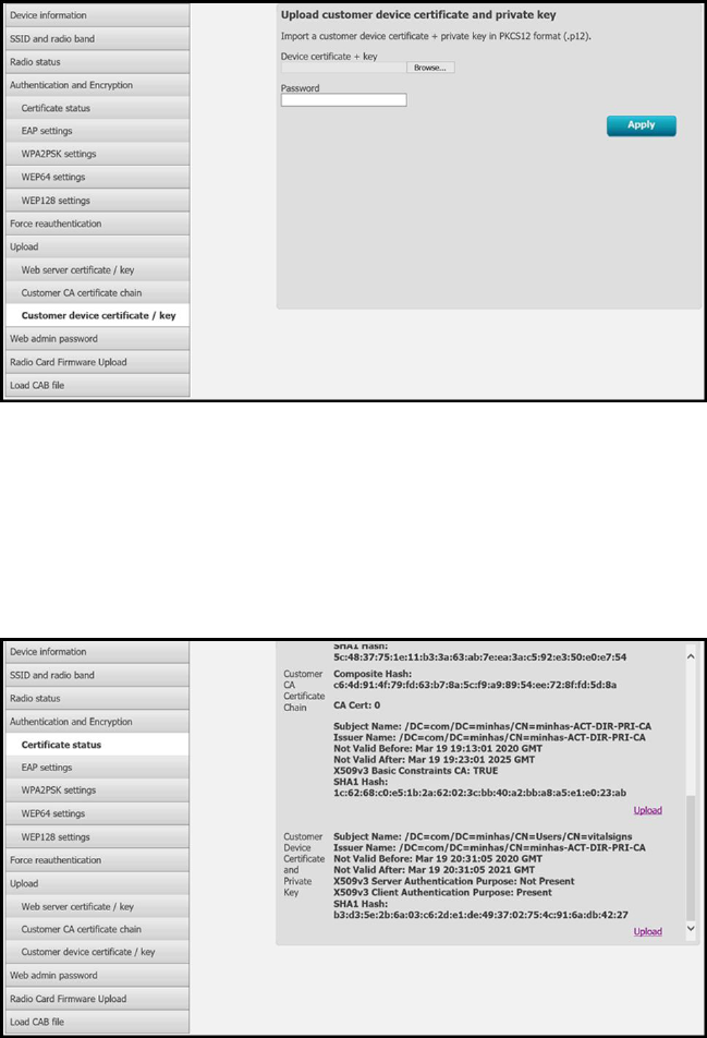
6. Click Browse to navigate to the Client Certificate file location on the PC.
7. Enter the Password for the client certificate.
8. Click Apply to load the Client Certificate onto the device.
To check the status of the wireless radio certificates:
1. Under the Authentication and Encryption section, click the Certificate status tab to view the
Customer CA Certificate Chain >CA Root Certificate and the Customer Device Certificate and
Private Key >Client Certificate details.
2. To confirm the presence of valid certificates on the CVSM/CIWS (Lamarr) device, configure the
Radio to an SSID with the authentication type: EAP-TLS.
A successful wireless connection with the SSID confirms the validity of wireless certificates.
Service manual Connex Direct 323

The CVSM/CIWS (Lamarr) can now be configured to use certificates on the wireless network.
NOTE For CVSM/CIWS (Lamarr), the Restore Factory Defaults (Radio Settings or All
Settings) does not delete the Wireless Radio Certificates on the device.
Import/Install an Active Directory server certificate on the Active Directory server
These instructions apply to Active Directory servers with Windows Server 2012 OS and above:
1. Press the Windows key + R to bring up the Run command.
2. Type mmc and press Enter to open the Microsoft Management Console.
3. Click the File menu and then select Add/Remove Snap-in....
4. Select Certificates from the list of Snap-ins, and click Add.
324 Connex Direct

5. In the next dialog box, select Computer account and click Next.
6. Select Local computer and click Finish.
7. From the “Add or Remove Snap-ins” window, click OK.
Click > to view the certificates folder. When you open any certificates folder, you will see
certificates displayed in the right pane.
8. Import/Install the AD Server Certificate into the following folder: Certificates (Local Computer)
> Personal > Certificates.
9. Right-click the Certificates folder under Personal and choose All Tasks > Import.
10. Follow the Certificate Import Wizard and provide the Active Directory Server Certificate file
path.
Service manual Connex Direct 325

NOTE An example Active Directory server certificate is shown
below.
Import/Install a Certificate Authority (CA) Root certificate on the Active Directory server
These instructions apply to Active Directory servers with Windows Server 2012 OS and above:
1. Press the Windows key + R to bring up the Run command.
2. Type mmc and press Enter to open the Microsoft Management Console.
3. Click the File menu and then select Add/Remove Snap-in....
4. Select Certificates from the list of Snap-ins, and click Add.
326 Connex Direct

5. In the next dialog box, select Computer account and click Next.
6. Select Local computer and click Finish.
7. From the “Add or Remove Snap-ins” window, click OK.
Click > to view the certificates folder. When you open any certificates folder, you will see
certificates displayed in the right pane.
8. Import/Install the CA Root Certificate into the following folder: Certificates (Local Computer) >
Trusted Root Certification Authorities > Certificates.
9. Right-click the Certificates folder under Trusted Root Certification Authorities and choose All
Tasks > Import.
Service manual Connex Direct 327

10. Follow the Certificate Import Wizard and provide the CA Root Certificate file path.
NOTE An example CA Root Certificate is shown below.
Import/Install a CA Root Certificate onto the device (includes CSM, CVSM, and CIWS)
Use the WA CSM Configuration Tool web application to install or import a CA Root Certificate onto
the device. The Config file (*-signed.waconfig) is generated by the Configuration Tool. See "Log into
the Configuration Tool" and "Configure a CA Root certificate using the Configuration Tool".
Create third party AD CS Certificate Authority Certificates
Third Party Certificates (AD Server & CA Root) need to be requested from the Third Party Certificate
Authority with the required Active Directory Server information.
AD CS Certificates (AD Server & CA Root) are auto-generated during the AC CS Role Installation and
Configuration on the AD Server. No specific process is required after the installation and
configuration of the AD CS Role on the AD Server to generate these certificates.
328 Connex Direct

HL7 out-of-box - setup details
HL7 (Direct EMR connection) setup
1. Access the Advanced Settings.
a. Touch the Settings tab.
b. Touch the Advanced tab.
c. Touch Enter Password.
d. Enter your password and touch OK.
The General tab appears.
2. Touch the Network tab.
3. Touch the Server tab.
4. Select Manual Entry from the drop-down list of the Connectivity method.
5. Select Direct EMR Connection from the Server drop-down list .
6. Select Data encryption to turn the Security on or off.
If Data encryption is enabled , then Server Authentication can be turned on or off. Data
encryption is intended to keep data secure while the data is transferred over a network.
NOTE Check or Uncheck Data encryption per the intended Secure
(TLS) or unsecure connection.
7. Select Authentication to turn the server authentication on or off.
NOTE Server Authentication is the process of confirming the
identity of the EMR Server by receiving a server certificate from the
server and checking it against the installed CA Root certificates on
the device.
• If checked, confirm that CA Root Certificate is loaded on the device and that the
Server Certificate is loaded on the EMR Server for the successful connection.
• If unchecked, the CA Root Certificate on the device and Server Certificate on the
EMR Server are not required for the successful connection.
8. Touch the keyboard to enter an IP Address, Episodic server host name, or FQDN of the EMR
Server in the Episodic server host name or IP address field.
Service manual Connex Direct 329

9. Touch the keyboard to enter an IP Address, Continuous server host name, or FQDN in the
Continuous server host name or IP Address field for the Continuous server that is listening for a
connection.
10. Touch the keyboard to enter an IP Address, Service server host name, or FQDN of the
Service server in the Service server host name or IP address field.
11. If needed, touch the keypad to enter a Port number in the Port field for the Episodic,
Continuous, or Service server that is listening for a connection.
12. Touch Test to test the connection of the device to the EMR Server.
NTP server- setup details
Set up the NTP server
1. Access the Advanced Settings.
a. Touch the Settings tab.
b. Touch the Advanced tab.
c. Touch Enter password.
d. Enter your password and touch OK.
The General tab appears.
2. Touch the Date/Time tab.
3. Touch the Enable NTP checkbox to enable NTP.
NOTE Check the Enable NTP option as the first step of connecting
with the NTP server to synchronize the device Date/Time clock over
the internal or external (Internet) network.
4. Enter the Host name or IP address of the NTP server.
To enter this information, touch the keypad in the Host name or IP address text field and enter
either the Host name or IP address of the NTP server.
5. Touch Test to test the connection of the device to the NTP Server and to synchronize the
device Date/Time.
330 Connex Direct

Project workflow
Service manual Connex Direct 331

Troubleshooting
Problem Possible cause Suggested action
Date/Time “Test network connection” failed The device is not connected
to a network and therefore
does not have an IP address
Verify that the device has an IP
address: Settings > Advanced
> “IP address”.
The device does not have a
properly configured NTP
server
Review the NTP server
configuration and make sure
NTP is properly configured.
The device does not have a
properly configured NTP
connection
Verify the Date/Time
configuration on the device:
Settings > Advanced > General
> Date/Time:
a. “Enable NTP” is checked.
b. The proper NTP server
address appears in the
“Domain” field (Domain, FQDN,
or IP Address).
The device does not have
Internet connectivity
Connect the device to the
Internet. (An Internet
connection is required when
the NTP server is outside the
local network.
Your network firewall is
blocking UDP port 123
Verify that the network’s NTP
port is open: typically, UDP 123.
The path to NTP server
cannot be reached
The path to NTP server cannot
be reached
Server “Test network connection” failed The device is not connected
to a network and therefore
does not have an IP address
Verify that the device has an IP
address: Settings > Advanced
> IP address.
The device does not have a
properly configured HL7
server connection
Verify the server configuration
on the device: Settings >
Advanced > Network > Server:
a. Server connectivity = Direct
EMR Connection.
b. Host IP is selected.
c. The proper address appears
in the Host Address field
(FQDN or IP Address).
d. The proper port appears in
the Host Port field.
Server authentication failed Load the proper Root
Certificate on the server and
the proper CA Root Certificate
in the device using the device
configuration tools.
332 Connex Direct

Problem Possible cause Suggested action
Your network firewall is
blocking the TCP port used
for the HL7 host connection
Verify that the network’s TCP
host port is open.
The path to EMR server
cannot be reached
Check network topology to
ensure there’s a valid path
from the device to the EMR
server.
Active Directory “Test network connection”
failed
The device is not connected
to a network and therefore
does not have an IP address
Verify that the device has an IP
address: Settings > Advanced
> IP address.
The device does not have a
properly configured Active
Directory server connection
Verify the server configuration
on the device: Settings >
Advanced > Network > Active
Directory:
a. “Enable Active Directory” is
selected.
b. The proper domain name
appears in the “Domain name”
field.
c. The proper group name
appears in the “Group” field.
d. You are using the proper
Clinician ID type, it matches
what you are scanning, and
the clinician is in the Active
Directory.
e. You are using the proper
Authentication User name.
f. You are using the proper
Authentication password.
Server authentication failed Load the proper Root
Certificate on the server and
the proper CA Root Certificate
in the device using the device
configuration tools.
Path to Active Directory
server cannot be reached
Check network topology to
ensure there’s a valid path
from the device to the Active
Directory server.
Date/Time is incorrect on the device Time zone is configured
incorrectly
Confirm the device’s time zone
configuration is set to the
correct time zone.
DST adjustment is not
configured correctly
Configure the DST setting
appropriately (enable or
disable DST adjustment
depending on location).
Service manual Connex Direct 333

Problem Possible cause Suggested action
The device is syncing time to
a different source than the
rest of the network
Configure the device to
configure its date and time to
the same source as the rest of
the network.
Failed to identify a patient The device is not connected
to a network and therefore
does not have an IP address
Verify that the device has an IP
address: Settings > Advanced
> IP address.
The device does not have a
properly configured HL7
server connection
Verify the server configuration
on the device: Settings >
Advanced >Network > Server:
a. “Server connectivity” = Direct
EMR Connection.
b. “Host IP” is selected.
c. The proper address appears
in the “Host Address” field
(FQDN or IP Address).
d. The proper port appears in
the “Host Port” field.
Scanned patient ID is not the
proper barcode
Verify the patient ID scanned is
a valid patient ID barcode.
Scanned patient ID could
not be found in the host
database containing the
patient census
Verify the patient ID scanned is
in the host database.
The HL7 host is not properly
configured to receive census
query requests
Verify that the host is
configured to receive census
query requests on the
configured port.
Your network firewall is
blocking the TCP port used
for the HL7 host connection
Verify that the network’s TCP
host port is open.
Server authentication failed Load the proper Root
Certificate on the server and
the proper CA Root Certificate
in the device using the device
configuration tools.
Failed to authenticate a user The device is not connected
to a network and therefore
does not have an IP address
Verify that the device has an IP
address: Settings > Advanced
> IP address.
Scanned Clinician ID is not
the proper barcode
Verify the Clinician ID scanned
is a valid Clinician ID barcode.
Scanned Clinician ID is not
contained in the user
authentication database
Verify the Clinician ID scanned
is in the user authentication
database.
334 Connex Direct

Problem Possible cause Suggested action
The device does not have a
properly configured Active
Directory server connection
Verify the server configuration
on the device: Settings >
Advanced > Network > Active
Directory:
a. “Enable Active Directory” is
selected.
b. The proper domain name
appears in the “Domain name”
field.
c. The proper group name
appears in the “Group” field.
d. You are using the proper
Clinician ID type, it matches
what you are scanning, and
the clinician is in the Active
Directory.
e. You are using the proper
Authentication User name.
User ID entered is not valid Verify that the user ID entered
is accurate and a valid ID in the
Active Directory.
Server authentication failed Load the proper Root
Certificate on the server and
the proper CA Root Certificate
in the device using the device
configuration tools.
Failed to send vitals The device is not connected
to a network and therefore
does not have an IP address
Verify that the device has an IP
address: Settings > Advanced
> IP address.
The device does not have a
properly configured HL7
server connection
Verify the server configuration
on the device: Settings >
Advanced > Network > Server:
a. Server connectivity = Direct
EMR Connection.
b. Host IP is selected.
c. The proper address appears
in the Host Address field
(FQDN or IP Address).
d. The proper port appears in
the Host Port field.
Your network firewall is
blocking the TCP port being
used for the HL7 host
connection
Verify that the network’s TCP
host port is open.
Server authentication failed Load the proper Root
Certificate on the server and
the proper CA Root Certificate
in the device using the device
configuration tools.
Service manual Connex Direct 335

Problem Possible cause Suggested action
The configured custom data
cannot be imported into the
EMR
Verify the custom data
configuration and make sure
the fields going to the EMR
match what the EMR is
expecting.
EMR response does not
match device interface
Verify EMR response to the
device’s HL7 interface
specification.
The EMR rejected the
Clinician ID
Verify Clinician ID sent from the
device is a valid Clinician ID for
the EMR.
EMR or interface engine is
down
Call your EMR or system
administrator.
Data was rejected for one of
the following reasons:
• Patient ID not found
• Clinician ID not found
• vitals date/time in the
future
• device received a
message timeout
notification
Check the EMR or interface
engine message logs to
determine root cause.
Troubleshooting the CVSM/CIWS (Newmar & Lamarr)
The CVSM/CIWS do not have a direct connection to the radio through a debug connection, so all
troubleshooting will be done on the device.
Verify if a CA Root certificate is loaded on the radio
To check if the CA Root certificate is loaded, navigate to: Advanced > Network > Radio
• Enable radio selected
• ESSID = Enter an WPA2-Enterprise SSID
• Set the Authentication type to WPA2-Enterprise (Newmar) or WPA2-AES (Lamarr)
• Set the EAP Type to PEAP-MSCHAPv2 (Newmar) or PEAP (Lamarr)
• Check the Server validation box
(Newmar Only - Lamarr doesn’t have Server validation option)
• Enter valid Identity & Password
• Touch Configure radio
Newmar
If the "Configuration invalid without certificates. Install certificates and try again." message appears in
the banner, the CA Root Certificate is not loaded.
Lamarr
If the CVSM/CIWS does not connect to the WLAN, the CA Root Certificate is not loaded.
336 Connex Direct

Verify if a Client certificate is loaded
To check if the Client certificate is loaded, navigate to: Advanced > Network > Radio
• Enable radio selected
• ESSID = Enter an WPA2-Enterprise SSID
• Set the Authentication type to WPA2-Enterprise (Newmar) or WPA2-AES (Lamarr)
• Set the EAP Type to TLS
• Check the Server validation box
(Newmar Only - Lamarr doesn’t have Server validation option)
• Enter valid Identity
• Touch Configure radio
Newmar
If the "Configuration invalid without certificates. Install certificates and try again." message appears in
the banner, the Client Certificate is not loaded.
Lamarr
If the CVSM/CIWS does not connect to the WLAN, the CA Root Certificate is not loaded.
NOTE Newmar Radio version 2.00.02 will encrypt the password file which is stored
at: /etc/welchallyn/clientpassword or /pacpasword.
Service manual Connex Direct 337
338 Connex Direct

Service record
Print theService record pages to enter and save the
results of your tests.
Date: Time:
Device name: Serial number:
Technician: Service tool version:
Leak test
Leak test Specification Actual reading Pass Fail
Leak test: Max: 5
Overpressure test
Overpressure test Specification Actual reading
Over Pressure Test: Adult mode: 280 . . . . 329
Neonate mode: 130 . . . .164
NIBP accuracy check
Target pressure ± 5 mmHg Pressure meter Service tool Specification Pass Fail
0 mmHg mmHg mmHg ± 1 mmHg
50 mmHg mmHg mmHg ± 3 mmHg
150 mmHg mmHg mmHg ± 3 mmHg
339

250 mmHg mmHg mmHg ± 3 mmHg
Masimo SpO2, SpHb, heart rate, and RRa tests
Test Specification Actual reading Pass Fail
SpO2 heart rate
61 bpm
Pulse rate 61 ±1 bpm
59 to 61 bpm
bpm
SpO2 saturation
81%
Saturation 81% ±3%
78 to 84%
%
SpHb g/dL
14 g/dL
SpHb 14 g/dL ±1 g/dL
13 g/dL to 15 g/dL
g/dL
RRa A measurement between 5
and 16 breaths per minute
breaths
per
minute
Nellcor SpO2 and heart rate test
Test Specification Actual reading Pass Fail
SpO2 heart rate
60 bpm
Pulse rate 60 ±1 bpm
59 to 61 bpm
bpm
SpO2 saturation
90%
Saturation 90% ±1 sat point
89 to 91%
%
340 Service record

Calibration key temperature test for SureTemp Plus
Temperature test Specification ± 0.2°F (± 0.1°C) Actual reading Pass Fail
97.3 °F (36.3°C) 97.1 to 97.5°F 36.2 to 36.4°C °F or °C
SureTemp Plus test
9600 Plus Calibration Tester ID
number Calibration Date Next Calibration Due Date
Temperature
tested Specification Range Actual reading Pass Fail
96.8 °F (36.0 °C) ± 0.3 °F (± 0.2 °C) 96.5 °F to 97.1
°F
35.8 °C to 36.2
°C
°F or
°C
101.3 °F (38.5 °C) ± 0.2 °F (± 0.1 °C) 101.1 °F to
101.5 °F
38.4 °C to 38.6
°C
°F or
°C
105.8 °F (41.0 °C) ± 0.3 °F (± 0.2 °C) 105.5 °F to
106.1 °F
40.8 °C to 41.2
°C
°F or
°C
Braun ThermoScan PRO 4000 or PRO 6000 test
9600 Plus Calibration Tester ID
number Calibration Date Next Calibration Due Date
Temperature tested Specification ± 0.4 °F (± 0.2 °C) Actual reading Pass Fail
96.8 °F (36.0 °C) 96.4 °F to 97.2 °F 35.8 °C to 36.2 °C °F or °C
101.3 °F (38.5 °C) 100.9 °F to 101.7 °F 38.3 °C to 38.7 °C °F or °C
105.8 °F (41.0 °C) 105.4 °F to 106.2 °F 40.8 °C to 41.2 °C °F or °C
Service manual Service record 341

ECG functional test record
Inspection of module and cables
Step Acceptance criteria Pass Fail
1 No missing parts, cuts, cracks, or discoloration to ECG patient cables
2 No missing parts, cuts, cracks, or discoloration to USB cable
3 No broken plastic, cracks, discoloration, missing parts, or rattle to module
ECG module LED test
Step Acceptance criteria Pass Fail
1 ECG module LED is off
3 ECG module LED is amber then steady green
5 ECG module LED is flashing green
Waveform and heart rate test
Step Acceptance criteria Displayed heart rate Pass Fail
3 Waveform present (normal sinus rhythm)
Heart rate 80 ♥/min +/- 3 ♥/min
Lead I HR ♥/min
5 Lead II HR ♥/min
5 Lead III HR ♥/min
5 Lead V HR ♥/min
Lead-off alarm test
Step Acceptance criteria Lead Pass Fail
1 Connex device displays the following messages:
Alert: Cannot analyze ECG.
Technical alarm: Lead off
RA or R
3 LA or L
3 RL or N
3 LL or F
342 Service record

3 V1 or C1
Respiration test
Step Acceptance criteria RR Pass Fail
6 Respiration rate is 15 BPM +/- 2 BPM BPM
Arrhythmia alarm test
Step Acceptance criteria Delay Pass Fail
5 Asystole alarm triggered ≥ 4 seconds seconds
Pacemaker detection test
Step Acceptance criteria Lead Pass Fail
10 Pacer spike marker appears before each
QRS complex
Lead I
11 Lead II
11 Lead III
11 Lead V
CO2 calibration or calibration check
Measured CO2 Pass Fail
CO2 _______%
CO2 successfully calibrated on:
EarlySense check
Present Not present
Movement frame
Exit sensitivity
Service manual Service record 343
344 Service record
