
Report Concerning Space Data System Standards
GREEN BOOK
SPACE DATA LINK
PROTOCOLS—SUMMARY
OF CONCEPT AND
RATIONALE
INFORMATIONAL REPORT
CCSDS 130.2-G-3
September 2015

Report Concerning Space Data System Standards
SPACE DATA LINK
PROTOCOLS—SUMMARY
OF CONCEPT AND
RATIONALE
INFORMATIONAL REPORT
CCSDS 130.2-G-3
GREEN BOOK
September 2015

CCSDS REPORT CONCERNING THE SPACE DATA LINK PROTOCOLS
CCSDS 130.2-G-3 Page i September 2015
AUTHORITY
Issue: Informational Report, Issue 3
Date: September 2015
Location: Washington, DC, USA
This document has been approved for publication by the Management Council of the
Consultative Committee for Space Data Systems (CCSDS) and reflects the consensus of
technical panel experts from CCSDS Member Agencies. The procedure for review and
authorization of CCSDS Reports is detailed in Organization and Processes for the
Consultative Committee for Space Data Systems (CCSDS A02.1-Y-4).
This document is published and maintained by:
CCSDS Secretariat
National Aeronautics and Space Administration
Washington, DC, USA
E-mail: secretariat@mailman.ccsds.org
CCSDS REPORT CONCERNING THE SPACE DATA LINK PROTOCOLS
CCSDS 130.2-G-3 Page ii September 2015
FOREWORD
This document is a CCSDS Report, which contains background and explanatory material to
support the CCSDS Recommended Standards on the TC, TM and AOS Space Data Link
Protocols (references [1], [2], and [3], respectively), and the Communications Operation
Procedure-1 (reference [4]) that accompanies the TC Space Data Link Protocol.
Through the process of normal evolution, it is expected that expansion, deletion, or
modification of this document may occur. This Report is therefore subject to CCSDS
document management and change control procedures, which are defined in Organization
and Processes for the Consultative Committee for Space Data Systems (CCSDS A02.1-Y-4).
Current versions of CCSDS documents are maintained at the CCSDS Web site:
http://www.ccsds.org/
Questions relating to the contents or status of this document should be sent to the CCSDS
Secretariat at the e-mail address indicated on page i.
CCSDS REPORT CONCERNING THE SPACE DATA LINK PROTOCOLS
CCSDS 130.2-G-3 Page iii September 2015
DOCUMENT CONTROL
Document Title Date Status
CCSDS
130.2-G-1
Space Data Link Protocols—
Summary of Concept and Rationale,
Informational Report, Issue 1
December
2007
Original issue,
superseded
CCSDS
130.2-G-2
Space Data Link Protocols—
Summary of Concept and Rationale,
Informational Report, Issue 2
November
2012
Issue 2, superseded
CCSDS
130.2-G-3
Space Data Link Protocols—
Summary of Concept and Rationale,
Informational Report, Issue 3
September
2015
Current issue

CCSDS REPORT CONCERNING THE SPACE DATA LINK PROTOCOLS
CCSDS 130.2-G-3 Page iv September 2015
CONTENTS
Section Page
1 INTRODUCTION .......................................................................................................... 1-1
1.1 PURPOSE ............................................................................................................... 1-1
1.2 SCOPE .................................................................................................................... 1-1
1.3 ORGANIZATION OF THIS REPORT .................................................................. 1-1
1.4 DEFINITIONS ........................................................................................................ 1-2
1.5 REFERENCES ....................................................................................................... 1-3
2 WHAT ARE THE SPACE DATA LINK PROTOCOLS? -
ARCHITECTURAL INTRODUCTION ........................................................................ 2-1
2.1 DESIGN GOALS ................................................................................................... 2-1
2.2 BASIC CONCEPTS ............................................................................................... 2-1
2.3 LAYER ARCHITECTURE .................................................................................... 2-3
3 WHAT DO THE SPACE DATA LINK PROTOCOLS PROVIDE? -
FROM USERS’ PERSPECTIVE ................................................................................... 3-1
3.1 SERVICES .............................................................................................................. 3-1
3.2 SERVICE FEATURES ........................................................................................... 3-2
3.3 SERVICES PROVIDED BY THE SPACE DATA LINK PROTOCOLS ............. 3-8
3.4 TYPICAL EXAMPLE .......................................................................................... 3-12
4 WHAT DO THE SPACE DATA LINK PROTOCOLS PERFORM? -
FROM DEVELOPERS’ PERSPECTIVE ..................................................................... 4-1
4.1 TRANSFER FRAMES ........................................................................................... 4-1
4.2 VIRTUAL CHANNELS ......................................................................................... 4-1
4.3 ADDRESSING AND MULTIPLEXING ............................................................... 4-3
4.4 RETRANSMISSION .............................................................................................. 4-5
4.5 TRANSFER OF PACKETS ................................................................................... 4-7
5 FREQUENTLY ASKED QUESTIONS ON THE SPACE DATA LINK
PROTOCOLS ................................................................................................................ 5-1
5.1 HOW DO THE SPACE DATA LINK PROTOCOLS DIFFER
FROM HDLC? ....................................................................................................... 5-1
5.2 ARE THE SPACE DATA LINK PROTOCOLS SECURE
PROTOCOLS? ....................................................................................................... 5-1
5.3 WHAT ARE THE MANAGED PARAMETERS ON A CCSDS
SPACE DATA LINK? ............................................................................................ 5-1

CCSDS REPORT CONCERNING THE SPACE DATA LINK PROTOCOLS
CCSDS 130.2-G-3 Page v September 2015
CONTENTS (continued)
Section Page
5.4 CAN COP-1 BE APPLIED TO DEEP SPACE COMMANDING? ...................... 5-2
5.5 CAN COP-1 BE APPLIED TO BLIND COMMANDING? .................................. 5-2
ANNEX A ACRONYMS .................................................................................................. A-1
ANNEX B SUMMARY OF SERVICES ..........................................................................B-1
Figure
2-1 Space Link .................................................................................................................... 2-2
2-2 Frequently Used Combinations of Space Data Link Protocols .................................... 2-3
2-3 Layer Architecture ........................................................................................................ 2-4
3-1 A Service Provided by a Space Data Link Protocol ..................................................... 3-2
3-2 Asynchronous Service Model ....................................................................................... 3-6
3-3 Synchronous Service Model ......................................................................................... 3-7
3-4 Example of How TM-SDLP Provides Services ......................................................... 3-13
4-1 Virtual Channels ........................................................................................................... 4-2
4-2 An Example of How to Use Virtual Channels .............................................................. 4-2
4-3 Hierarchy of the Identifiers and Channels Used by the Space Data Link Protocols .... 4-3
B-1 Graphical Conventions .................................................................................................B-2
B-2 TC Data Link Services ..................................................................................................B-3
B-3 Service Provided by TM-SDLP ....................................................................................B-4
B-4 AOS Data Link Services ...............................................................................................B-5
Table
3-1 Services Provided by the Space Data Link Protocols
................................................... 3-8
CCSDS REPORT CONCERNING THE SPACE DATA LINK PROTOCOLS
CCSDS 130.2-G-3 Page 1-1 September 2015
1 INTRODUCTION
1.1 PURPOSE
This Report has been developed to present the concept and rationale of the CCSDS
Recommended Standards on the TC, TM, and AOS Space Data Link Protocols (references
[1], [2], and [3], respectively), and the Communications Operation Procedure-1 (reference
[4]) that accompanies the TC Space Data Link Protocol.
It has specifically been prepared to serve the following purposes:
a) to provide an architectural overview of the Space Data Link Protocols;
b) to provide information on how the Space Data Link Protocols should be used by users
to transfer various kinds of data over space data links;
c) to provide information on how the Space Data Link Protocols should be deployed in
space data systems to process and transfer data supplied by users.
1.2 SCOPE
The information contained in this Report is not part of the CCSDS Recommended Standards
on the Space Data Link Protocols (references [1]–[3]) or the Communications Operation
Procedure-1 (reference [4]). Proximity-1 Space Link Protocol—Rationale, Architecture, and
Scenarios (reference [8]) explains the concepts and rationale of the Proximity-1 Space Data
Link Protocol (reference [7]). Therefore, this report addresses only the TC, TM, and AOS
Space Data Link protocols. Furthermore only the Data Link Layer of the ISO protocol model
is addressed. The Overview of Space Communication Protocols (reference [12]) provides a
general introduction to the five Layers (Physical, Data Link, Network, Transport,
Application) of the ISO reference model for which CCSDS provides protocol specifications.
The Recommended Standards are the controlling specifications in the event of any conflict
between the Recommended Standards and the material presented herein.
1.3 ORGANIZATION OF THIS REPORT
This document is divided into five numbered sections and two annexes:
a) section 1 presents the purpose, scope, and organization of this Report, and lists the
definitions and references used throughout the Report;
b) section 2 explains what the Space Data Link Protocols are and how they are used in
the protocol stack used over space links;
c) section 3 explains the services provided by the Space Data Link Protocols and their
features;
CCSDS REPORT CONCERNING THE SPACE DATA LINK PROTOCOLS
CCSDS 130.2-G-3 Page 1-2 September 2015
d) section 4 shows how the Space Data Link Protocols should be implemented in
onboard and ground data systems;
e) section 5 presents frequently asked questions and their answers;
f) annex A lists acronyms and abbreviations used within this document;
g) annex B contains a quick summary of the services provided by the Space Data Link
Protocols.
1.4 DEFINITIONS
The following definitions are used throughout this Report. Many other terms that pertain to
specific items are defined in the appropriate sections.
aperiodic: not periodic (see below).
asynchronous: not synchronous (see below).
Mission Phase: a period of a mission during which specified communications
characteristics are fixed. The transition between two consecutive Mission Phases may cause
an interruption of the communications services.
periodic: of or pertaining to a sequence of events in which each event occurs at a fixed time
interval (within specified tolerance) after the previous event in the sequence.
Physical Channel: a stream of bits transferred over a space link in a single direction.
space link: a communications link between a spacecraft and its associated ground system or
between two spacecraft. A space link consists of one or more Physical Channels in one or
both directions.
synchronous: of or pertaining to a sequence of events occurring in a fixed time relationship
(within specified tolerance) to another sequence of events. It should be noted that
‘synchronous’ does not necessarily imply ‘periodic’ or ‘constant rate’.
Space Data Link Protocols: Data Link Layer protocols specified in references [1]–[3],
which have been developed to transfer space application data over space-to-ground, ground-
to-space, or space-to-space com
munications links.
Transfer Frames: Protocol Data Units of the Space Data Link Protocols.
CCSDS REPORT CONCERNING THE SPACE DATA LINK PROTOCOLS
CCSDS 130.2-G-3 Page 1-3 September 2015
1.5 REFERENCES
The following documents are referenced in this Report. At the time of publication, the
editions indicated were valid. All documents are subject to revision, and users of this Report
are encouraged to investigate the possibility of applying the most recent editions of the
documents indicated below. The CCSDS Secretariat maintains a register of currently valid
CCSDS documents.
[1] TC Space Data Link Protocol. Issue 3. Recommendation for Space Data System
Standards (Blue Book), CCSDS 232.0-B-3. Washington, D.C.: CCSDS, September
2015.
[2] TM Space Data Link Protocol. Issue 2. Recommendation for Space Data System
Standards (Blue Book), CCSDS 132.0-B-2. Washington, D.C.: CCSDS, September
2015.
[3] AOS Space Data Link Protocol. Issue 3. Recommendation for Space Data System
Standards (Blue Book), CCSDS 732.0-B-3. Washington, D.C.: CCSDS, September
2015.
[4] Communications Operation Procedure-1. Issue 2. Recommendation for Space Data
System Standards (Blue Book), CCSDS 232.1-B-2. Washington, D.C.: CCSDS,
September 2010.
[5] Organization and Processes for the Consultative Committee for Space Data Systems.
Issue 4. CCSDS Record (Yellow Book), CCSDS A02.1-Y-4. Washington, D.C.:
CCSDS, April 2014.
[6] Information Technology—Open Systems Interconnection—Basic Reference Model: The
Basic Model. 2nd ed. International Standard, ISO/IEC 7498-1:1994. Geneva: ISO,
1994.
[7] Proximity-1 Space Link Protocol—Data Link Layer. Issue 5. Recommendation for
Space Data System Standards (Blue Book), CCSDS 211.0-B-5. Washington, D.C.:
CCSDS, December 2013.
[8] Proximity-1 Space Link Protocol—Rationale, Architecture, and Scenarios. Issue 2.
Report Concerning Space Data System Standards (Green Book), CCSDS 210.0-G-2.
Washington, D.C.: CCSDS, December 2013.
[9] TC Synchronization and Channel Coding. Issue 2. Recommendation for Space Data
System Standards (Blue Book), CCSDS 231.0-B-2. Washington, D.C.: CCSDS,
September 2010.
[10] TM Synchronization and Channel Coding. Issue 2. Recommendation for Space Data
System Standards (Blue Book), CCSDS 131.0-B-2. Washington, D.C.: CCSDS, August
2011.
CCSDS REPORT CONCERNING THE SPACE DATA LINK PROTOCOLS
CCSDS 130.2-G-3 Page 1-4 September 2015
[11] Radio Frequency and Modulation Systems—Part 1: Earth Stations and Spacecraft.
Issue 25. Recommendation for Space Data System Standards (Blue Book), CCSDS
401.0-B-25. Washington, D.C.: CCSDS, February 2015.
[12] Overview of Space Communications Protocols. Issue 3. Report Concerning Space Data
System Standards (Green Book), CCSDS 130.0-G-3. Washington, D.C.: CCSDS, July
2014.
[13] Space Packet Protocol. Issue 1. Recommendation for Space Data System Standards
(Blue Book), CCSDS 133.0-B-1. Washington, D.C.: CCSDS, September 2003.
[14] “Registries.” Space Assigned Number Authority. http://sanaregistry.org/r/.
[15] “Packet Version Number.” Space Assigned Numbers Authority.
http://sanaregistry.org/r/packet_version_number/.
[16] Encapsulation Service. Issue 2. Recommendation for Space Data System Standards
(Blue Book), CCSDS 133.1-B-2. Washington, D.C.: CCSDS, October 2009.
[17] CCSDS Global Spacecraft Identification Field Code Assignment Control Procedures.
Issue 6. Recommendation for Space Data System Standards (Blue Book), CCSDS
320.0-B-6. Washington, D.C.: CCSDS, October 2013.
[18] The Application of CCSDS Protocols to Secure Systems. Issue 2. Report Concerning
Space Data System Standards (Green Book), CCSDS 350.0-G-2. Washington, D.C.:
CCSDS, January 2006.
[19] Space Link Extension—Forward Space Packet Service Specification. Issue 2.
Recommendation for Space Data System Standards (Blue Book), CCSDS 912.3-B-2.
Washington, D.C.: CCSDS, July 2010.
[20] TC Synchronization and Channel Coding—Summary of Concept and Rationale. Issue
2. Report Concerning Space Data System Standards (Green Book), CCSDS 230.1-G-2.
Washington, D.C.: CCSDS, November 2012.
[21] Space Data Link Security Protocol. Issue 1. Recommendation for Space Data System
Standards (Blue Book), CCSDS 355.0-B-1. Washington, D.C.: CCSDS, September
2015.
[22] Reference Architecture for Space Data Systems. Issue 1. Recommendation for Space
Data System Practices (Magenta Book), CCSDS 311.0-M-1. Washington, D.C.:
CCSDS, September 2008.
[23] Space Communications Cross Support—Architecture Description Document. Issue 1.
Report Concerning Space Data System Standards (Green Book), CCSDS 901.0-G-1.
Washington, D.C.: CCSDS, November 2013.
CCSDS REPORT CONCERNING THE SPACE DATA LINK PROTOCOLS
CCSDS 130.2-G-3 Page 1-5 September 2015
[24] Space Communications Cross Support—Architecture Requirements Document. Issue 1.
Recommendation for Space Data System Practices (Magenta Book), CCSDS 901.1-M-1.
Washington, D.C.: CCSDS, May 2015.
[25] Licklider Transmission Protocol (LTP) for CCSDS. Issue 1. Recommendation for
Space Data System Standards (Blue Book), CCSDS 734.1-B-1. Washington, D.C.:
CCSDS, May 2015.
[26] Space Link Extension Services—Executive Summary. Issue 2. Report Concerning Space
Data System Standards (Green Book), CCSDS 910.0-G-2. Washington, D.C.: CCSDS,
March 2006.
[27] IP over CCSDS Space Links. Issue 1. Recommendation for Space Data System
Standards (Blue Book), CCSDS 702.1-B-1. Washington, D.C.: CCSDS, September
2012.
[28] Extensible Space Communication Cross Support—Service Management—Concept.
Issue 1. Report Concerning Space Data System Standards (Green Book), CCSDS
902.0-G-1. Washington, D.C.: CCSDS, September 2014.
CCSDS REPORT CONCERNING THE SPACE DATA LINK PROTOCOLS
CCSDS 130.2-G-3 Page 2-1 September 2015
2 WHAT ARE THE SPACE DATA LINK PROTOCOLS? -
ARCHITECTURAL INTRODUCTION
2.1 DESIGN GOALS
The Space Data Link Protocols are protocols of the Data Link Layer of the OSI Basic
Reference Model (reference [6]). They were designed by CCSDS to m
eet the requirements
of space missions for efficient transfer of space application data of various types and
characteristics on space links.
Most of the present-day spacecraft use micro-processors for processing data (e.g., for
compressing data, checking the status of subsystems, executing timelines, etc.). As a result,
they need to send and receive various types of data (e.g., compressed images, housekeeping
telemetry, event reports, commands, timelines, etc.) that have different Quality of Service
(QoS) requirements in terms of data volume, data rate, latency, reliability, and so on.
However, since the processing capability available onboard spacecraft is limited due to the
physical constraints imposed by the fact that the spacecraft are flying, the protocols must be
simple enough to be implemented by small hardware and/or processors. The Space Data
Link Protocols have the capability of transferring various kinds of data with different QoS
requirements using relatively simple algorithms. Further, care was taken to ensure that these
protocols are upper-compatible with the basic data formats used by earlier spacecraft.
CCSDS has developed four Space Data Link Protocols: the TC Space Data Link Protocol (TC-
SDLP, reference [1]), the TM Space Data Link Protocol (TM-SDLP, reference [2]), the AOS
Space Data Link Protocol (AOS-SDLP, reference [3]), and the Data Link Layer of the
Proximity-1 Space Link Protocol (reference [7]). Since there is a separate CCSDS Report that
explains the concept and rationale of the Proximity-1 Space Link Protocol (reference [8]), this
Report deals only with TC-SDLP, TM-SDLP, and AOS-SDLP.
2.2 BASIC CONCEPTS
A space link is defined to be a com
munications link between a spacecraft (which may be a
lander or a rover on a distant planet) and its associated ground system or between two
spacecraft. Therefore at least one end of a space link is a spacecraft of some kind.
A space link consists of one or more Physical Channels in one or both directions. A Physical
Channel is defined to be a stream of bits transferred over a space link in a single direction. A
space link usually consists of one forward Physical Link for sending commands from the
ground system to the spacecraft, and one or multiple return Physical Links (possibly using
multiple frequency bands) for sending telemetry from the spacecraft to the ground system
(see figure 2-1).

CCSDS REPORT CONCERNING THE SPACE DATA LINK PROTOCOLS
CCSDS 130.2-G-3 Page 2-2 September 2015
Spacecraft
Forward
Physical Link
Return
Physical Links
Ground System
Figure 2-1: Space Link
Each Space Data Link Protocol provides one-way transfer from the sending end to the
receiving end of a Physical Channel, but the TC-SDLP usually uses a service provided by the
TM-SDLP or AOS-SDLP on a different Physical Channel in the other direction of the same
space link (see 4.4) to provide feedback from the receiving end to the sending end. However,
it is possible to use the same Space Data Link Protocol, such as AOS-SDLP, for both
directions on a single space link. In such cases, one instance of the Space Data Link Protocol
is used on a Physical Channel in one direction and another instance on another Physical
Channel in the other direction.
On a given Physical Channel, only one Space Data Link Protocol must be used (i.e., multiple
Space Data Link Protocols must not be mixed on a single Physical Channel).
The TC-SDLP is usually used for (but not limited to) sending commands from a ground
system to a spacecraft on a forward Physical Link. The TM-SDLP is usually used for (but
not limited to) sending telemetry from a spacecraft to a ground system on a return Physical
Link. The AOS-SDLP is also used for sending telemetry from a spacecraft to a ground
system on a return Physical Link, but it may be used on a forward Physical Link as well if
there is a need for two-way on-line communications (e.g., for audio and video, or for high-
rate communications in either direction) between a spacecraft and a ground system.
Assuming that a space link consists of one forward Physical Link and one return Physical
Link, there are three combinations of Space Data Link Protocols that are frequently used by
space missions (see figure 2-2). Combination (a) of figure 2-2 has been used by most
missions, while combination (b) is used by missions that require extended features provided
by AOS-SDLP for the return Physical Link. Combination (c) is used by missions such as
piloted missions that need two-way on-line communications between the spacecraft and the
ground system or need high-rate communication.

CCSDS REPORT CONCERNING THE SPACE DATA LINK PROTOCOLS
CCSDS 130.2-G-3 Page 2-3 September 2015
TC-SDLP (forward)
TM-SDLP (return)
Ground
System
Spacecraft
(a) TC-SDLP and TM-SDLP
TC-SDLP (forward)
AOS-SDLP (return)
Ground
System
Spacecraft
(b) TC-SDLP and AOS-SDLP
AOS-SDLP (forward)
AOS-SDLP (return)
Ground
System
Spacecraft
(c) AOS-SDLP for both directions
Figure 2-2: Frequently Used Combinations of Space Data Link Protocols
2.3 LAYER ARCHITECTURE
Figure 2-3 shows how the Space Data Link Protocols are used with other protocols of other
layers and how they are related with the OSI Basic Reference Model (reference [6]).
CCSDS defines two Sublayers in the Data Link Layer of the OSI Model: the Data Link Protocol
Sublayer and the Synchronization and Channel Coding Sublayer. The Space Data Link
Protocols belong to the Data Link Protocol Sublayer, which specifies m
ethods of transferring
data supplied by the higher layer over a space link using data units known as Transfer Frames.
The Synchronization and Channel Coding Sublayer specifies methods for reliably transferring
Transfer Frames over noisy space links, which include methods of delimiting and
synchronization of Transfer Frames and methods of error correction and/or detection.

CCSDS REPORT CONCERNING THE SPACE DATA LINK PROTOCOLS
CCSDS 130.2-G-3 Page 2-4 September 2015
CCSDS has developed two standards for the Synchronization and Channel Coding Sublayer:
1
the TC Synchronization and Channel Coding Recommended Standard (reference [9]), and
the TM Synchronization and Channel Coding Recommended Standard (reference [10]).
When the TC Space Data Link Protocol is used, the TC Synchronization and Channel Coding
Recommended Standard must be used for the Synchronization and Channel Coding
Sublayer. Likewise, when the TM or AOS Space Data Link Protocol is used, the TM
Synchronization and Channel Coding Recommended Standard must be used for the
Synchronization and Channel Coding Sublayer.
Higher-layer
Protocols
Sync & Channel
Coding
Spacecraft
RF &
Modulation
Space Data
Link Protocol
Higher-layer
Protocols
Sync & Channel
Coding
Ground System
RF &
Modulation
Space Data
Link Protocol
Space Link
Data Link
Protocol
Sublayer
Sync & Channel
Coding
Sublayer
Data Link
Layer
Network Layer and
above
Physical Layer
Figure 2-3: Layer Architecture
Below the Synchronization and Channel Coding Recommended Standards, Physical Layer
protocols (for example, the CCSDS RF and Modulation Systems defined in reference [11])
are used to transmit delimited and coded Transfer Frames over space links.
1
A third CCSDS-developed standard for the Synchronization and Channel Coding Sublayer of the Proximity-1
Space Link Protocol is outside the scope of this Report (cf. 2.1).
CCSDS REPORT CONCERNING THE SPACE DATA LINK PROTOCOLS
CCSDS 130.2-G-3 Page 2-5 September 2015
Above the Space Data Link Protocols, higher-layer protocols belonging to the Network
Layer and above use the services provided by the Space Data Link Protocols. Most of these
higher-layer protocols are end-to-end protocols and are responsible for transferring data from
end to end across the entire network, which contains the space link.
How the Space Data Link Protocols should be used in the entire space data system is
explained in reference [12]. Reference [24] defines a set of requirements for CCSDS-
recommended configurations for secure Space Communications Cross Support (SCCS)
architectures to be used as a common framework when CCSDS Agencies 1) provide and use
SCCS services, and 2) develop systems that provide interoperable SCCS services supported
by the space data link and related services and cross support services (see reference [23]).
CCSDS REPORT CONCERNING THE SPACE DATA LINK PROTOCOLS
CCSDS 130.2-G-3 Page 3-1 September 2015
3 WHAT DO THE SPACE DATA LINK PROTOCOLS PROVIDE? -
FROM USERS’ PERSPECTIVE
3.1 SERVICES
The Space Data Link Protocols provide protocols of the Network and higher layers with
services to transfer data over a space link. The entities (i.e., the elements that implement
communications protocols) of the Space Data Link Protocols are called service providers and
the entities that use services are called service users.
A service provided by a service provider (an entity that implements the Space Data Link and
associated service protocols—see reference [23]) transfers data supplied by a service user
(sending user) to another service user (receiving user) over a space link (see figure 3-1). In
doing this, the Space Data Link Protocol uses the capabilities of the Synchronization and
Channel Coding Sublayer and the Physical Layer as explained in 2.3. Howe
ver, the physical
characteristics of the space link are invisible to the service users.
The point at which a service is provided by a service provider for a service user is called a
Service Access Point (SAP). Each SAP has a SAP address, and the service user that uses the
service through the SAP is also identified by the SAP address. In figure 3-1, there are two
SAPs: one for the sending user and the other for the receiving user. In this case, these two
SAPs share the same SAP address because these SAPs provide the same service to the
sending and receiving users.
The sending user of a service passes Service Data Units (SDUs) and Service Control
Information (SCI) to the service provider. The SDUs are the data that are delivered to the
receiving user. The service control information is used to specify how the SDUs should be
handled by the service provider.
In the case of TC-SDLP, the sending user may receive from the service provider information
on the status of the delivery of SDUs to the receiving user.

CCSDS REPORT CONCERNING THE SPACE DATA LINK PROTOCOLS
CCSDS 130.2-G-3 Page 3-2 September 2015
Sending
User
Receiving
User
SCI
SDU
SDU
Space Data Link Protocol
(Service Provider)
Figure 3-1: A Service Provided by a Space Data Link Protocol
The interactions between a service user and a service provider are defined in the form of
‘primitives’. Primitives present an abstract model of the logical exchange of SDUs and
control information between the service provider and the service user, but they do not specify
how the interactions should be implemented.
3.2 SERVICE FEATURES
3.2.1 DIRECTIONALITY
All the services provided by the Space Data Link Protocols are unidirectional. The sending
user of a service can send data to the receiving user using a service provider, but it cannot
receive data from the receiving user using the same service provider (see figure 3-1). If the
sending user also requires to receive data from some user, it must use a service of a different
service provider (of the same or a different Space Data Link Protocol) that provides services
in the other direction.
3.2.2 RELIABILITY
3.2.2.1 General
The reliability guaranteed by the services depends on the protocol used and, in some cases,
the service type selected by the user.
CCSDS REPORT CONCERNING THE SPACE DATA LINK PROTOCOLS
CCSDS 130.2-G-3 Page 3-3 September 2015
3.2.2.2 Reliability Provided by TC-SDLP
3.2.2.2.1 General
Most of the services provided by the TC Space Data Link Protocol (TC-SDLP) have two
service types: the Sequence-Controlled Service (or the Type-A Service) and the Expedited
Service (or the Type-B Service). The service types determine how reliably the SDUs
supplied by the sending user are delivered to the receiving user.
Sending users of a service that has two service types specify for each SDU whether Type-A
or Type-B should be applied. Both service types are provided by the Communications
Operation Procedure-1 (COP-1) specified in reference [4].
3.2.2.2.2 Sequence-Controlled (Type-A) Service
The Type-A Service utilizes an Automatic Repeat Request (ARQ) procedure, i.e., a form of
automated retransmission of the ‘go-back-n’ type. It is implemented by sequence-control
mechanisms, which include retransmissions of lost data, at both sending and receiving ends
of the space link. It also uses a standard report returned from the receiving end to the
sending end using a service of the protocol used in the other direction on the space link.
The automated retransmission works well for near-Earth missions: the round-trip time delay
is short, so COP-1 can respond efficiently to the need for retransmission of a lost frame.
However, where longer round-trip light times are involved (e.g., deep space) the response is
less efficient than it is for the near-Earth case. The sending end transmits a sequence of
frames and then waits. Any COP-1 automatic retransmission happens only after a long wait
time. During the long wait time, the uplink is unused. Performance and efficiency can be
improved by using retransmissions without waiting for the response from the receiving end
or by adopting an upper layer protocol like LTP (see 3.2.2.4). Section 8 of the TC
Synchronization and Channel Coding Green Book (reference [20]) discusses options and
scenarios for systematic retransmission.
The service provider guarantees, with a high probability of success, complete, in-sequence
delivery of Type-A SDUs supplied by a sending user at a single SAP (i.e., no SDU is lost,
duplicated, or delivered out of sequence). However, there is no guarantee that Type-A SDUs
supplied at multiple SAPs by multiple sending users will be delivered to the receiving users
in the order initially supplied.
CCSDS REPORT CONCERNING THE SPACE DATA LINK PROTOCOLS
CCSDS 130.2-G-3 Page 3-4 September 2015
3.2.2.2.3 Expedited (Type-B) Service
The Type-B Service is normally used either in exceptional operational circumstances,
typically during spacecraft recovery operations, or when a higher layer protocol provides a
retransmission capability.
For the Type-B Service, SDUs supplied by the sending user are transmitted only once (i.e.,
no retransmission is performed). The service provider does not guarantee that all Type-B
SDUs are delivered to the receiving user. However, the sequence of Type-B SDUs supplied
by the sending user at a SAP is preserved through the transfer over the space link, although
there may be gaps in the sequence of SDUs delivered to the receiving user.
If SDUs of both service types are supplied at a SAP, the sequence of Type-A SDUs and the
sequence of Type-B SDUs are both preserved through the transfer over the space link, but
the entire sequence of both SDUs may not be preserved.
3.2.2.3 Reliability Provided by TM-SDLP and AOS-SDLP
Neither the TM Space Data Link Protocol (TM-SDLP) nor the AOS Space Data Link
Protocol (AOS-SDLP) guarantees completeness of the SDUs delivered to the receiving users,
but some services may signal gaps in the sequence of delivered SDUs. These protocols do
not provide the sending users with a confirmation that data has been received by the
receiving users.
The sequence of SDUs supplied by the sending user at a SAP is preserved through the
transfer over the space link, although there may be gaps in the sequence of SDUs delivered
to the receiving user. The order of SDUs submitted to different SAPs is not maintained.
3.2.2.4 Reliability Provided by Licklider Transmission Protocol
The Licklider Transmission Protocol (LTP) provides optional reliability mechanisms on top
of an underlying (usually data link) communication service. LTP sits between the Data Link
and the Network Layers of the ISO stack and provides optionally reliable communications
over a single data link hop. LTP was originally developed for space communication and is
largely derived from the Acknowledged-mode procedures of the CCSDS File Delivery
Protocol (CFDP).
LTP does not provide an ‘in-order delivery’ service between different LTP blocks. That is,
the order of arrival of LTP blocks may not be the order in which they were submitted to the
sending LTP engine for transmission. If ‘in-order delivery’ is desired, other protocol options
within CCSDS are available.
Reference [25] should be consulted for further information about the LTP protocol and
options.
CCSDS REPORT CONCERNING THE SPACE DATA LINK PROTOCOLS
CCSDS 130.2-G-3 Page 3-5 September 2015
3.2.3 PRIORITY AND LATENCY
The mechanism used by the Space Data Link Protocols for transferring data with different
priority and latency requirements is the use of ‘Virtual Channels’. The Virtual Channel
facility allows one Physical Channel to be divided into multiple separate logical data
channels, each known as a Virtual Channel (VC). Each Virtual Channel carries a separate
sequence of SDUs, which may have different priority and latency requirements from those
carried on the other Virtual Channels.
By using an appropriate algorithm for multiplexing Virtual Channels onto the Physical
Channel, the priority and latency requirements of SDUs can be met to some extent (see 4.2).
CCSDS does not recommend any standard algorithm for multiplexing Virtual Channels. It is
the responsibility of the project to ensure that the multiplexing algorithm used for that project
actually satisfies the requirements.
The TC-SDLP optionally uses Multiplexer Access Point (MAP) Channels to multiplex
different sequences of SDUs, each of which may have different priority and latency
requirements, onto one Virtual Channel.
If the SLE Forward Space Packet Protocol Service (reference [19]) is used on the ground to
forward Space Packets (reference [13]) to be transmitted to a spacecraft using the TC-SDLP,
the algorithm specified in reference [19] must be used for multiplexing Virtual Channels and
MAP Channels. Otherwise, CCSDS does not recommend any standard algorithm for
multiplexing MAP or Virtual Channels, and it is the responsibility of the project to ensure
that the multiplexing algorithm used for that project actually satisfies the requirements.
3.2.4 TRANSFER TIMING
3.2.4.1 General
The timing at which SDUs supplied by the sending users are transferred over the space link
and delivered to the receiving users differs depending on the protocol and the service
implementation and agreed priorities. The discussion in this subsection assumes that the
sending or receiving user is transmitting and receiving data via a ground station using the
CCSDS Space Link Extension (SLE) services that are designed to provide interoperability
and cross support.
3.2.4.2 Transfer Timing of TC-SDLP
The TC Space Data Link Protocol does not specify any rules for the timing of the transfer of
SDUs supplied by the sending user. The user may submit SDUs at any time, but the timing
of actual data transfer is determined by the SLE service provider in accordance with mission-
specific rules (such as multiplexing algorithms or scheduled release times) and may depend
on the data traffic at the time of transfer. It should be noted that the SLE service provider
may require more constraints on the start of an SDU transmission.

CCSDS REPORT CONCERNING THE SPACE DATA LINK PROTOCOLS
CCSDS 130.2-G-3 Page 3-6 September 2015
3.2.4.3 Transfer Timing of TM-SDLP and AOS-SDLP
3.2.4.3.1 General
The TM and AOS Space Data Link Protocols have three service types (asynchronous,
synchronous, and periodic) that determine the timing at which SDUs supplied by the sending
user are transferred over the space link.
3.2.4.3.2 Asynchronous Service
In asynchronous service, there are no timing relationships between the submission of SDUs
by the service user and their transfer by the service provider over the space link. The sending
user may request data transfer at any time, but the timing of actual data transfer is determined
by the service provider in accordance with mission-specific rules (such as multiplexing
algorithms) and may depend on the data traffic at the time of transfer.
Sending
User
Receiving
User
Queue
Space Data Link Protocol
(Service Provider)
Figure 3-2: Asynchronous Service Model
In this service type (figure 3-2), each SDU from a sending user is placed in a queue, the
contents of which are sent to a receiving user in the order in which they were presented.
Although transmission errors may prevent delivery of some SDUs, the service provider
attempts to transfer all SDUs provided by the sending user exactly once. The key feature of
this service type is that all of the SDUs from the sending user are transferred, and transferred
only once.
3.2.4.3.3 Synchronous Service
In synchronous service, the transfer of SDUs is synchronized with the release by the service
provider of Transfer Frames associated with the service. The transfer timing may be periodic
or aperiodic.

CCSDS REPORT CONCERNING THE SPACE DATA LINK PROTOCOLS
CCSDS 130.2-G-3 Page 3-7 September 2015
In this service (figure 3-3), each SDU from a sending user is placed in a buffer that can hold
only one SDU; the content of the buffer is sent to a receiving user at the time when a
Transfer Frame associated with the service is transmitted. The transmission timing of
Transfer Frames is determined by the service provider according to mission-specific rules
(which are usually specified by or known to the user). The key feature of this service type is
that the timing of data transfer is driven by the transfer mechanism, not by individual service
requests from the user. Thus a particular SDU from a sending user might be sent once,
several times (if the ‘new’ value is not placed in the buffer soon enough), or not at all (if one
value is replaced by a second before the service provider can send it).
Sending
User
Receiving
User
Buffer
Space Data Link Protocol
(Service Provider)
Figure 3-3: Synchronous Service Model
3.2.4.3.4 Periodic Service
Periodic service is a special case of synchronous service in which SDUs are transferred at a
constant rate. Periodic transfer from service interface to service interface is provided with a
specified maximum delay and a specified maximum jitter at the service interface. A
synchronous service is periodic if the channel associated with the service (which is either a
Virtual Channel or a Master Channel) transfers SDUs at a constant rate. (Virtual Channels
and Master Channels are logical data channels established over a space link and will be
explained in 4.2 and 4.3, respectively).
For periodic services, all SDUs are sent only once if the sending user supplies SDUs at the
same rate as the rate at which the service provider transfers them.
3.2.5 CHANNELS
For each instance of a service, SDUs are transferred over a channel (either a Physical Channel,
a Master Channel, a Virtual Channel, or a MAP Channel (TC-SDLP only)). In addition to the
Virtual Channels and MAP Channels explained in 3.2.3, the Space Data Link Protocols use
Physical Channels and Master Channels. Physical Channels are explained in 2.2. A Master
Channel is a set of Virtual Channels associated with one spacecraft. In most cases, a Physical
Channel has only one Master Channel, but it may consist of multiple Master Channels.
Subsection 4.3 explains how these channels are identified and multiplexed.

CCSDS REPORT CONCERNING THE SPACE DATA LINK PROTOCOLS
CCSDS 130.2-G-3 Page 3-8 September 2015
3.3 SERVICES PROVIDED BY THE SPACE DATA LINK PROTOCOLS
3.3.1 GENERAL
Table 3-1 shows the services provided by the Space Data Link Protocols categorized by the
types of SDUs transferred by the services. A schematic summary of these services is found
in annex B.
Table 3-1: Services Provided by the Space Data Link Protocols
Type of Service
Data Units
TM Space Data
Link Protocol
TC Space Data
Link Protocol
AOS Space Data
Link Protocol
Packets (NOTE 1) Packet Service,
Encapsulation
Service
MAP Packet Service,
VC Packet Service,
Encapsulation
Service
Packet Service,
Encapsulation
Service
Fixed-length private
data
VC Access Service (None) VC Access Service
Variable-length private
data
(None) MAP Access Service,
VC Access Service
(None)
Short fixed-length data VC FSH Service
(NOTE 2),
MC FSH Service,
VC OCF Service
(NOTE 3),
MC OCF Service
(None) Insert Service,
VC OCF Service
(NOTE 3)
Bitstream (None) (None) Bitstream Service
Transfer Frames VC Frame Service,
MC Frame Service
VC Frame Service,
MC Frame Service
VC Frame Service,
MC Frame Service
NOTES
1 Packets directly transferred by the Space Data Link Protocols must have Packet
Version Numbers authorized by CCSDS. These Packet Version Numbers are found
in reference [15]. Other packets can be transferred using the Encapsulation Service
defined in reference [16]. In order to transfer IP datagrams over the CCSDS space
link, an additional shim protocol, defined in reference [27] is required. IP over
CCSDS utilizes the Encapsulation Packet as the data structure that contains the IP
datagram
.
2 FSH = Frame Secondary Header.
3 OCF = Operational Control Field.
CCSDS REPORT CONCERNING THE SPACE DATA LINK PROTOCOLS
CCSDS 130.2-G-3 Page 3-9 September 2015
3.3.2 SERVICES TO TRANSFER PACKETS
3.3.2.1 General
The Space Data Link Protocols provide services for transferring various types of SDUs on
space links, but the most important services are those for transferring variable-length data units
commonly known as Packets, that is, Protocol Data Units of protocols of the Application Layer,
such as the Space Packet Protocol (reference [13]), or of the Network Layer, such as IP
(reference [27]).
Each packet format transferred by the Space Data Link Protocols must have a Packet Version
Number (PVN) authorized by CCSDS. A list of the PVNs presently authorized by CCSDS is
contained in reference [14]. A user of this service is a protocol entity that sends or receives
Packets with a single PVN.
3.3.2.2 Services to Transfer Packets Provided by TC-SDLP
The TC-SDLP has two services for transferring packets: the MAP (Multiplexer Access
Point) Packet Service (or the MAPP Service) and the Virtual Channel Packet Service (or the
VCP Service). These services transfer a sequence of Packets over a space link on a MAP
Channel (in the case of the MAPP Service) or a Virtual Channel (in the case of VCP
Service).
Both Sequence-Controlled (Type-A) and Expedited (Type-B) service types (see 3.2.2.2) are
provided for these services. The sending user specifies for each Packet whether Type-A or
Type-B should be applied.
Different users (i.e., Packets with different PVNs) can share a single MAP Channel (in the
case of the MAPP Service) or a single Virtual Channel (in the case of the VCP Service), and
if there are multiple users on a MAP or VC Channel, the service provider multiplexes
Packets with different PVNs to form a single stream of Packets to be transferred on that
channel.
3.3.2.3 Service to Transfer Packets Provided by TM-SDLP and AOS-SDLP
The TM-SDLP and AOS-SDLP each have a service called the Packet Service for transferring
Packets. A sequence of Packets supplied by a sending user is transferred on a single Virtual
Channel.
These services do not guarantee complete delivery of the Packets supplied by the sending
user to the receiving user, nor do they signal gaps in the sequence of Packets delivered to the
receiving user.
Different users (i.e., Packets with different PVNs) can share a single Virtual Channel, and if
there are multiple users on a Virtual Channel, the service provider multiplexes Packets with
different PVNs to form a single stream of Packets to be transferred on that Virtual Channel.
CCSDS REPORT CONCERNING THE SPACE DATA LINK PROTOCOLS
CCSDS 130.2-G-3 Page 3-10 September 2015
3.3.3 ENCAPSULATION SERVICE
Packets with authorized PVNs can be directly transferred by the Space Data Link Protocols
using the services explained in 3.3.2. Packets that do not have an authorized PVN can be
transferred with a service called the Encapsulation Service, defined in reference [16]. With this
service, Packets are transferred encapsulated in either Space Packets defined in reference [13]
or Encapsulation Packets defined in reference [16].
This service can be used with any Space Data Link Protocol and it uses a service provided by
the underlying Space Data Link Protocol to transfer Packets.
3.3.4 SERVICES TO TRANSFER PRIVATE DATA
3.3.4.1 General
The Space Data Link Protocols provide services to transfer sequences of privately formatted
SDUs (i.e., SDUs not formatted as Packets).
3.3.4.2 Services to Transfer Private Data Provided by TC-SDLP
The TC-SDLP provides two services to transfer sequences of privately formatted SDUs: the
MAP Access (MAPA) Service and the Virtual Channel Access (VCA) Service.
The MAPA and VCA Services transfer sequences of privately formatted SDUs of variable
length across a space link over a MAP Channel or a Virtual Channel, respectively.
For the VCA Service, the length of the SDUs transferred by this service is constrained by the
length of the Transfer Frames (see 4.1) used by the service provider. The MAPA Service
includes a segmentation function, so the length constraint does not apply to SDUs transferred
by the MAPA Service.
Both Sequence-Controlled (Type-A) and Expedited (Type-B) service types (see 3.2.2.2) are
provided for these services. The sending user specifies for each SDU whether Type-A or
Type-B should be applied.
In a Virtual Channel that provides the VCA Service, only one user can use this service, and
SDUs from different users are not multiplexed together within the Virtual Channel. In a
MAP Channel that provides the MAPA Service, only one user can use this service, and
SDUs from different users are not multiplexed together within the MAP Channel.
3.3.4.3 Services to Transfer Private Data Provided by TM-SDLP and AOS-SDLP
The TM-SDLP and AOS-SDLP each provide a VCA Service that transfers a sequence of
privately formatted SDUs of fixed length over a Virtual Channel across a space link. The
length of the SDUs transferred by this service is determined by the length of the Transfer
Frames (see 4.1) used by the service provider.
CCSDS REPORT CONCERNING THE SPACE DATA LINK PROTOCOLS
CCSDS 130.2-G-3 Page 3-11 September 2015
The VCA Service is either asynchronous (see 3.2.4.3.2) or periodic (see 0). The service does
not guarantee completeness, but it may signal gaps in the sequence of SDUs delivered to the
receiving user.
In a Virtual Channel that provides the VCA Service, only one user can use this service, and
SDUs from different users are not multiplexed together within the Virtual Channel.
3.3.5 SERVICES TO TRANSFER SHORT, FIXED-LENGTH DATA
3.3.5.1 General
The TM-SDLP and AOS-SDLP provide services to transfer sequences of short, fixed-length
SDUs. These services are used to transfer, at relatively short intervals, data used for
spacecraft operations (for example, reports on command reception or data used for clock
calibration). These services are synchronous (see 3.2.4.3.3).
3.3.5.2 Services to Transfer Short, Fixed-Length Data Provided by TM-SDLP
The TM-SDLP provides four services to transfer sequences of short, fixed-length SDUs: the
Virtual Channel Frame Secondary Header (VC_FSH) Service, the Virtual Channel
Operational Control Field (VC_OCF) Service, the Master Channel Frame Secondary Header
(MC_FSH) Service and the Master Channel Operational Control Field (MC_OCF) Service.
The VC_FSH and VC_OCF Services provide transfer of fixed-length SDUs synchronized
with the release of Transfer Frames of a Virtual Channel. The MC_FSH and MC_OCF
Services provide transfer of fixed-length SDUs synchronized with the release of Transfer
Frames of a Master Channel.
These services do not guarantee completeness but may signal gaps in the sequence of SDUs
delivered to the receiving user.
In a Virtual or Master Channel that provides one of the above services, only one user can use
this service, and SDUs from different users are not multiplexed together within the Virtual or
Master Channel. However, one or more users of the Packet or Virtual Channel Access
Service may coexist in the Virtual or Master Channel used to support this service.
3.3.5.3 Services to Transfer Short, Fixed-Length Data Provided by AOS-SDLP
The AOS-SDLP provides two services to transfer sequences of short, fixed-length SDUs: the
VC_OCF Service and the Insert Service.
The VC_OCF Service provides transfer of fixed-length SDUs synchronized with the release
of Transfer Frames of a Virtual Channel. The Insert Service provides transfer of fixed-length
SDUs synchronized with the release of Transfer Frames of a Physical Channel.
CCSDS REPORT CONCERNING THE SPACE DATA LINK PROTOCOLS
CCSDS 130.2-G-3 Page 3-12 September 2015
These services do not guarantee completeness but may signal gaps in the sequence of SDUs
delivered to the receiving user.
In a Virtual Channel that provides the VC_OCF Service or in a Physical Channel that
provides the Insert Service, only one user can use this service, and SDUs from different users
are not multiplexed together within the Virtual or Physical Channel. However, one or more
users of the Packet or VCA Service may coexist in the Virtual or Physical Channel used to
support this service.
3.3.6 SERVICES TO TRANSFER FRAMES
The Space Data Link Protocols each have two services to transfer Transfer Frames over a
space link: the Virtual Channel Frame (VCF) Service and the Master Channel Frame (MCF)
Service. Since Transfer Frames are generated by the Space Data Link Protocols, these
services are used by entities of the Space Data Link Protocols, not by entities of protocols of
higher layers as is the case for the other services.
The VCF (or MCF) Service provides transfer of a sequence of Transfer Frames, created by
an independent protocol entity of the same protocol, on a Virtual (or Master) Channel across
a space link.
In a Virtual or Master Channel that provides the VCF or MCF Service, only one user can use
the service, and SDUs from different users are not multiplexed together within the Virtual or
Master Channel.
The VCF and MCF Services provided by the TC-SDLP do not guarantee completeness. The
service provider does not make any distinction between Type-A and Type-B Services (see
3.2.2.2) for SDUs supplied by the user. The user should perform necessary procedures to
provide Type-A and Type-B Services.
The VCF and MCF Services provided by the TM-SDLP and AOS-SDLP do not guarantee
completeness but may signal gaps in the sequence of SDUs delivered to the receiving user.
Transfer Frames supplied as SDUs to these services must have the same length as those
generated by the service provider.
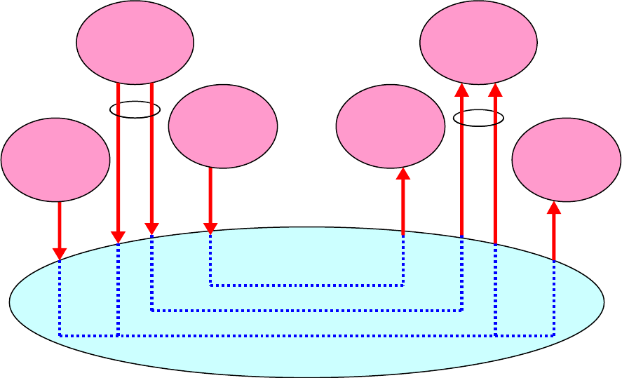
3.4 TYPICAL EXAMPLE
Figure 3-4 shows an example of how the TM Space Data Link Protocol provides users with
services for transferring various type of data over a space link.
In this example, there are three sending entities onboard a spacecraft and three receiving
entities on the ground, each receiving entity corresponding to one of the sending entities. (1)
An onboard entity of the Space Packet Protocol sends urgent and non-urgent Packets to a
ground entity of the same protocol over the space link. Onboard the spacecraft and on the
ground, there may be other entities of the Space Packet Protocol that are not shown in the
figure, but they are connected via onboard and ground links (or sub-networks), respectively,
CCSDS REPORT CONCERNING THE SPACE DATA LINK PROTOCOLS
CCSDS 130.2-G-3 Page 3-13 September 2015
and how they communicate within these links (or sub-networks) is outside the scope of this
document. (2) An onboard process for calibrating the onboard clock needs to send the current
value of the onboard clock to the corresponding process on the ground so that the ground
process can calibrate the onboard clock against the ground clock. (3) A stream of encrypted
data whose structure is unknown to the TM-SDLP needs to be sent over the space link.
V
C_OCF
Service
Space
Packet
Protocol
Packet
Service
TM Space Data
Link Protocol
VC 0
VC 1
VC 2
Encrypted
Data
Transfer
Clock
Calibration
Process
Clock
Calibration
Process
Encrypted
Data
Transfer
VC Access
Service
Space
Packet
Protocol
VC Access
Service
VC_OCF
Service
Packet
Service
Receiving Users On the GroundSending Users Onboard a Spacecraft
Figure 3-4: Example of How TM-SDLP Provides Services
The sequence of urgent and non-urgent Packets are transferred with two instances of the
Packet Service, each on a different Virtual Channel (urgent Packets on VC 0 and non-urgent
Packets on VC 1 in this case). It will be explained in 4.2 how the traffic on these two Virtual
Channels is handled and how their quality of service is controlled.
Since the clock calibration data is short and of a fixed length, it is transferred with the
VC_OCF Service, one of the services for transferring a sequence of short, fixed-length
SDUs. In this example, VC 0 is chosen for transferring clock calibration data.
The mechanism used in this example for transferring a stream of encrypted data, multiplexed
with the other data, is to use the VCA Service on VC 2, which is dedicated to the transfer of
encrypted data. The sending user generates a sequence of chunks of fixed length from the
stream of encrypted data and supplies them to the service provider as SDUs, which are
delivered to the receiving user for decryption.
CCSDS REPORT CONCERNING THE SPACE DATA LINK PROTOCOLS
CCSDS 130.2-G-3 Page 3-14 September 2015
3.5 SPACE LINK EXTENSION (SLE) SERVICES
The Space Link Extension (SLE) Services provide a set of cross support interfaces that give
service users who are remote from the space link terminals access to the space links for
transmission and reception. These interfaces permit controlled access to the service
production capabilities in the space link terminals. They effectively extend the CCSDS
return telemetry (TM), forward telecommand (TC), and forward Advanced Orbiting Systems
(AOS) Space Link services that are used by many spacecraft operators between ground
stations and spacecraft.
The return SLE Services associated with conventional TM/AOS include:
– Return All Frames (RAF), which provides the TM frames from a single space link bit
stream to spacecraft operators and other users who might need all the frames;
– Return Channel Frames (RCF), which provides Master Channel (MC) or specific
Virtual Channels (VCs), as specified by each RCF service user;
– Return Operational Control Field (ROCF), which provides MC or VC Operational
Control Fields (OCFs), as specified by each ROCF service user.
The forward SLE Services associated with conventional TC include:
– Forward Communications Link Transmission Unit (FCLTU), which enables users to
provide CLTUs (encoded TC frames) for uplink to spacecraft;
– Forward Space Packet (FSP), which enables single users to provide packets for
uplink to a spacecraft without needing to coordinate with other users of the
spacecraft;
– Enhanced Forward Communications Link Transmission Unit (EFCLTU), which
enables users to provide uncoded AOS (or TC) frames for uplink to spacecraft.
Additional information about these SLE services is provided in the CCSDS SLE Executive
Summary Green Book (reference [26]). In addition, both the SCCS-ADD (reference [23])
and the SCCS-ARD (reference [24]) provide the context for understanding the relationships
among all of these space data link protocols and the CCSDS Cross Support Services (CSS).
CCSDS REPORT CONCERNING THE SPACE DATA LINK PROTOCOLS
CCSDS 130.2-G-3 Page 4-1 September 2015
4 WHAT DO THE SPACE DATA LINK PROTOCOLS PERFORM? -
FROM DEVELOPERS’ PERSPECTIVE
4.1 TRANSFER FRAMES
4.1.1 GENERAL
The Protocol Data Units exchanged between entities of the Space Data Link Protocols are
called Transfer Frames. Transfer Frames used by the TC-SDLP, TM-SDLP, and AOS-SDLP
are called TC Transfer Frames, TM Transfer Frames, and AOS Transfer Frames,
respectively. Each Transfer Frame consists of a header which provides protocol control
information and a data field within which SDUs are carried.
4.1.2 TC TRANSFER FRAMES
The TC-SDLP uses variable-length Transfer Frames to facilitate reception of short messages
with a short delay. The length of each TC Transfer Frame is contained in its header. The
TC-SDLP uses another data unit called the Communications Link Control Word (CLCW).
CLCWs are usually transferred with a service provided by the TM-SDLP or the AOS-SDLP.
CLCWs are sent from the receiver to the sender of TC Transfer Frames and contain a report
that describes the status of acceptance of TC Transfer Frames at the receiver.
4.1.3 TM AND AOS TRANSFER FRAMES
The TM-SDLP and AOS-SDLP use fixed-length Transfer Frames to facilitate simple,
reliable, and robust synchronization procedures over weak-signal, noisy links. Their length
must be fixed on a particular Physical Channel during a Mission Phase and must be known to
the receiver through a management activity before the actual reception occurs. The length of
Transfer Frames must be determined according to the rules specified in reference [10].
4.2 VIRTUAL CHANNELS
The mechanism used by the Space Data Link Protocols for transferring data with different
QoS (Quality of Service, mostly priority and latency in this case) requirements is the use of
Virtual Channels. The Virtual Channel facility allows one Physical Channel to be divided
into multiple separate logical data channels, each known as a Virtual Channel (VC) and
identified by a Virtual Channel Identifier (VCID) (see figure 4-1). Each Virtual Channel
carries a separate sequence of SDUs, which m
ay have different QoS requirements from those
carried on the other Virtual Channels. Each Transfer Frame transferred over a Physical
Channel belongs to one of the Virtual Channels of the Physical Channel. It is the
responsibility of the user mission to determine and manage how Virtual Channels are used
and how mission QoS requirements are to be met by using this capability.

CCSDS REPORT CONCERNING THE SPACE DATA LINK PROTOCOLS
CCSDS 130.2-G-3 Page 4-2 September 2015
Physical Channel
Virtual Channel 0
Virtual Channel 1
Virtual Channel 2
Figure 4-1: Virtual Channels
Figure 4-2 shows an example that illustrates how Virtual Channels may be used to transfer
Packets with different QoS requirements. In this example, the Physical Channel has two
Virtual Channels: VC 0 for high-priority traffic and VC 1 for low-priority traffic. In
figure 4-2, a long, low-priority Packet (for memory upload or download, for example) is
being transmitted on VC 1. Since this Packet is longer than what can be carried by the
maximum-size Transfer Frame (if the TC-SDLP is used) or the fixed-length Transfer Frame
(if the TM-SDLP or AOS-SDLP is used), it is carried by two consecutive Transfer Frames of
VC 1. Then, when the first Transfer Frame carrying this low-priority Packet is being
transmitted, a short, high-priority Packet (carrying an on-off command or an event report, for
example) is generated. Since this high-priority Packet needs to be transmitted as soon as
possible, a Transfer Frame of VC 0 is generated to carry this high-priority Packet and
inserted between the first and second Transfer Frames of VC 1 that carry the low-priority
Packet. To use this kind of algorithm, a buffer memory with a sufficient capacity to store
SDUs and/or Transfer Frames temporarily must be implemented in the service provider.
High Priority Packet
Low Priority Packet
Transfer Frame of
VC 1: Low Priority
Transfer Frame of
VC 0: High Priority
Transfer Frame of
VC 1: Low Priority
Low Priority Packet High Priority Packet Low Priority Packet
Figure 4-2: An Example of How to Use Virtual Channels

CCSDS REPORT CONCERNING THE SPACE DATA LINK PROTOCOLS
CCSDS 130.2-G-3 Page 4-3 September 2015
The mission must develop the appropriate algorithm for multiplexing Transfer Frames of
different Virtual Channels so that the QoS requirements of SDUs can be met to some extent.
This is true for both forward transfers and return transfer from the spacecraft. If the SLE
Forward Space Packet Protocol Service (reference [19]) is used on the ground to forward
Space Packets to be transmitted to a spacecraft using the TC-SDLP, one of the algorithms
specified in reference [19] will be used for multiplexing Virtual Channels. Otherwise,
CCSDS does not recommend any standard algorithm for multiplexing Virtual Channels, and
it is the responsibility of the project to ensure that the multiplexing algorithm used for that
project actually satisfies the QoS requirements.
4.3 ADDRESSING AND MULTIPLEXING
4.3.1 GENERAL
The Space Data Link Protocols use some addresses or identifiers to identify data streams.
All the Space Data Link Protocols use the following identifiers: the Transfer Frame Version
Number (TFVN), the Spacecraft Identifier (SCID), the Virtual Channel Identifier (VCID)
(explained in 4.2), the Master Channel Identifier (MCID), and the Physical Channel Name.
In addition to these identifiers, the TC-SDLP optionally uses an identifier called the
Multiplexer Access Point Identifier (MAP ID).
Figure 4-3 shows the hierarchy of these identifiers and the channels identified by them.
Physical Channel:
Identified by Physical Channel Name
Master Channels (MC):
Identified by MCID=TFVN+SCID
V
irtual Channels (VC):
Identified by VCID
MAP Channels (TC-SDLP only, Optional):
Identified by MAP ID
Figure 4-3: Hierarchy of the Identifiers and Channels Used by the Space Data Link
Protocols
CCSDS REPORT CONCERNING THE SPACE DATA LINK PROTOCOLS
CCSDS 130.2-G-3 Page 4-4 September 2015
4.3.2 TRANSFER FRAME VERSION NUMBER
The Transfer Frame Version Number (TFVN) is used to distinguish among different Transfer
Frames. The values for the TC, TM, and AOS Transfer Frames are 1 (‘00’), 1 (‘00’), and 2
(‘01’), respectively. The numbers in the parentheses are binary encoded values that actually
appear in the header of Transfer Frames. The TC and TM Transfer Frames, which share the
same TFVN value, will be distinguished by management or configuration information.
4.3.3 SPACECRAFT IDENTIFIER
The Spacecraft Identifier (SCID) is used to identify the spacecraft associated with the space
link, but it must always be modified by the TFVN in order to identify the spacecraft
uniquely. In other words, there is a set of SCIDs (each of which consists of 10 bits) for
spacecraft that use the TC-SDLP and TM-SDLP (for which the value of TFVN is 1) and
another set of SCIDs (each of which consists of 8 bits) for spacecraft that use the AOS-SDLP
(for which the value of TFVN is 2).
The SCID assignment process is initiated by a designated Agency Representative, and it is
performed using a form found on the SANA SCID Registry (reference [14]). Since there are
a limited number of SCIDs, and an increasing number of spacecraft, SCIDs for spacecraft
that are no longer active must be relinquished for re-use. If a spacecraft uses the TC-SDLP on
the forward link and the AOS-SDLP on the return link, it must be assigned two SCIDs, one for
the TC-SDLP (TFVN=1) and the other for the AOS-SDLP (TFVN=2). How the SCIDs should
be assigned to spacecraft is specified in reference [17].
4.3.4 MASTER CHANNEL IDENTIFIER
The concatenation of a TFVN and a SCID is known as a Master Channel Identifier (MCID),
and it is the identifier that uniquely identifies the spacecraft. All Transfer Frames with the
same MCID on a Physical Channel constitute a Master Channel (MC). A Master Channel
consists of one or more Virtual Channels, each of which is identified with a VCID. The
concatenation of an MCID and a VCID is called a Global Virtual Channel Identifier
(GVCID).
In most cases, a Physical Channel carries only Transfer Frames of a single MCID, and in
these cases the Physical Channel is identical with the Master Channel identified with the
MCID. But a Physical Channel may carry Transfer Frames with multiple MCIDs (with the
same TFVN) and in these cases the Physical Channel consists of multiple Master Channels.
That is, Transfer Frames associated with multiple spacecraft may be multiplexed into a single
Physical Channel, but the length of all Transfer Frames must be the same if TM-SDLP or
AOS-SDLP is used.
Transfer Frames of different Space Data Link Protocols must not be multiplexed on a
Physical Channel.
CCSDS REPORT CONCERNING THE SPACE DATA LINK PROTOCOLS
CCSDS 130.2-G-3 Page 4-5 September 2015
4.3.5 PHYSICAL CHANNEL NAME
A Physical Channel is identified with a Physical Channel Name, which is set by management
and not included in the header of Transfer Frames. The Physical Channel Name is a
managed parameter in TM and AOS defined as a character string. It is also the Service
Access Point (SAP) address of the Insert Service for AOS.
4.3.6 MULTIPLEXER ACCESS POINT IDENTIFIER
The TC-SDLP uses an optional identifier called the Multiplexer Access Point Identifier
(MAP ID) that is used to create multiple streams of data within a Virtual Channel. All the
Transfer Frames on a Virtual Channel with the same MAP ID constitute a MAP Channel. If
the MAP ID is used, a Virtual Channel consists of one or multiple MAP Channels. Both
Virtual Channels and MAP Channels can be used for multiplexing streams of SDUs.
MAPs also provide the capability of segmenting Packets and other privately formatted SDUs
and must be used if Packets or SDUs whose lengths exceed the maximum length that can be
carried by Transfer Frames are to be transferred (see 4.5.2).
4.4 RETRANSMISSION
4.4.1 GENERAL
The TC-SDLP has the capability to retransmit lost or corrupted data to ensure delivery of
SDUs in sequence, without gaps or duplication, over a space link. This capability is
provided by a retransmission control mechanism realized by the Communications Operation
Procedure-1 (COP-1), which is defined in reference [4], when the Sequence-Controlled
(Type-A) Service is used. This Service only guarantees complete delivery of SDUs over the
space link, from sender to receiver (including any SLE services). If the SDUs traverses a
longer path, of which the space link is just one element, it does not guarantee complete end-
to-end delivery through the entire path.
The TC-SDLP can also use an optional systematic retransmission capability (see references
[1] and [9]) in the Synchronization and Channel Coding Sublayer. Reference [20] discusses
the use of the system
atic retransmission and the COP-1 automatic retransmission for deep
space missions.
Neither TM-SDLP nor AOS-SDLP has a retransmission capability, so retransmission must
be done by a higher-layer protocol (e.g., LTP—see 3.2.2.4 in reference [25]) if complete
delivery of data is required.
CCSDS REPORT CONCERNING THE SPACE DATA LINK PROTOCOLS
CCSDS 130.2-G-3 Page 4-6 September 2015
4.4.2 COMMUNICATIONS OPERATION PROCEDURE-1 (COP-1)
4.4.2.1 General
The TC-SDLP relies on forward error correction/detection mechanisms provided by the
Synchronization and Channel Coding Sublayer to support the error-free delivery of SDUs.
However, to improve protection against errors undetected by the Synchronization and Channel
Coding Sublayer, an error-control mechanism is also available in TC-SDLP. This mechanism,
in connection with the underlying services of the Synchronization and Channel Coding
Sublayer, provides a very high level of protection against errors introduced on the space link. It
is also advisable to use the Frame Error Control Field defined in reference [1] when the forward
error correction/detection capability provided by the Synchronization and Channel Coding
Sublayer is not sufficient. For information on the performance of the various error protection
options provided by the Channel Coding Sublayer and the TC-SDLP, refer to reference [20].
This error-control m
echanism of the TC-SDLP is provided by the Communications
Operation Procedure-1 (COP-1) when the Sequence-Controlled (Type-A) Service is used. It
is a closed-loop procedure executed by the sending and receiving ends of TC-SDLP, and
utilizes an automatic request for retransmission (ARQ) procedure of the ‘go-back-n’ type to
retransmit Transfer Frames that were rejected by the receiving end of the protocol. It allows
Transfer Frames to be accepted by the receiving end only if they are received in strict
sequential order, thus enabling the SDUs to be delivered to the layer above at the receiving
end, correct and without omission or duplication, and in the same sequential order in which
they were received from the layer above at the sending end.
COP-1 consists of a pair of synchronized procedures for each Virtual Channel: a Frame
Operation Procedure-1 (FOP-1) that executes within the sending entity; and a Frame
Acceptance and Reporting Mechanism-1 (FARM-1) that executes within the receiving entity.
The FOP-1 transmits Transfer Frames of a particular Virtual Channel to the FARM-1 of the
same Virtual Channel. The FARM-1 returns reports of the status of Transfer Frame
acceptance to the FOP-1 using data units called the Communications Link Control Words
(CLCWs), which are transmitted by a Space Data Link Protocol used on the other direction.
COP-1 provides two services (Sequence-Controlled Service and Expedited Service) that
determine how reliably SDUs supplied by the sending user are delivered to the receiving user.
4.4.2.2 Sequence-Controlled Service
The Sequence-Controlled Service (or the Type-A Service) is realized by an automatic request
for retransmission (ARQ) procedure of the ‘go-back-n’ type with sequence-control
mechanisms of both sending and receiving ends and a standard report returned from the
receiving end to the sending end using CLCWs.
For the Sequence-Controlled Service, COP-1 ensures with a high probability of success that
a) no SDU is lost;
b) no SDU is duplicated;
CCSDS REPORT CONCERNING THE SPACE DATA LINK PROTOCOLS
CCSDS 130.2-G-3 Page 4-7 September 2015
c) no SDU is delivered out of sequence.
For the Sequence-Controlled Service, TC-SDLP uses a type of Transfer Frames called
Type-A Transfer Frames. Control of sequentiality is maintained using the Frame Sequence
Number that must be present in each Type-A Transfer Frame. Type-A Transfer Frames are
transmitted by the FOP-1 with their Frame Sequence Numbers arranged in strict up-counting
order. The FARM-1 permits Type-A Transfer Frames to be accepted only if they are
received bearing Frame Sequence Numbers in the proper up-counting sequential order.
Upon detection of the first sequence error, the FARM-1 will reject all subsequent Type-A
Transfer Frames, on that Virtual Channel, which do not contain the expected Frame
Sequence Number. FOP-1 initiates retransmission either in response to a ‘Retransmit’ Flag
in the CLCW or by detecting a timeout. FOP-1 performs retransmission by re-sending all
unacknowledged Type-A Transfer Frames on that Virtual Channel. FOP-1 and FARM-1
also have a window mechanism to prevent a new Transfer Frame with the same Frame
Sequence Number as that of a missing Transfer Frame from being transmitted or accepted.
4.4.2.3 Expedited Service
The Expedited Service (or the Type-B Service) is normally used either in exceptional
operational circumstances, typically during spacecraft recovery operations, or when a higher-
layer protocol provides a retransmission capability.
For the Expedited Service, TC-SDLP uses a type of Transfer Frames called Type-B Transfer
Frames. Type-B Transfer Frames are also used to send Control Commands from the FOP-1
to the FARM-1. At the sending end, Type-B Transfer Frames are transmitted as close to
immediately as possible, and at the receiving end, the SDUs carried by Type-B Transfer
Frames will be delivered to the receiving user immediately. Type-B Transfer Frames are
transmitted only once (i.e., no retransmission), and there is no guarantee that all SDUs
transmitted with Type-B Transfer Frames are delivered to the receiving user.
Valid Type-B Transfer Frames will always be accepted by FARM-1, and processed only to
the extent of incrementing a counter for Type-B Transfer Frames in the CLCW. Type-B
Transfer Frames are protected by the error correction/detection capability of the underlying
Synchronization and Channel Coding Sublayer. Therefore Type-B Transfer Frames accepted
by FARM-1 have a very high probability that they are error-free, but their sequentiality is not
controlled by COP-1.
4.5 TRANSFER OF PACKETS
4.5.1 GENERAL
How Packets are transferred with Transfer Fram
es differs depending on the Space Data Link
Protocol. The following subsections provide an informal overview of the procedures for
transferring Packets with Transfer Frames. The exact procedures are specified in the
Recommended Standards (references [1], [2], and [3]).
CCSDS REPORT CONCERNING THE SPACE DATA LINK PROTOCOLS
CCSDS 130.2-G-3 Page 4-8 September 2015
4.5.2 TRANSFER OF PACKETS BY THE TC SPACE DATA LINK PROTOCOL
If MAPs (see 4.3.6) are used, Packets whose lengths exceed the maximum length that can be
carried by a Transfer Fram
e are sent by dividing them (i.e., by segmentation) into portions
that are compatible with insertion into Transfer Frames. In this case, each Transfer Frame
contains either a portion of a large Packet, a single complete Packet, or multiple complete
Packets. The portions of a divided Packet must be transferred in consecutive Transfer
Frames of the MAP Channel without being interlaced with other Packets or portions of other
Packets in the same MAP Channel.
If MAPs are not used, segmentation is not performed and each Transfer Frame contains
either a single complete Packet or multiple complete Packets.
When extracting multiple Packets from a single Transfer Frame, the length field of the
Packets is used. Therefore the location and meaning of the length field of the Packets
transferred over the space link must be known to the service provider. (The Packets
transferred by the TC-SDLP are limited to those with PVNs authorized by CCSDS.)
4.5.3 TRANSFER OF PACKETS BY THE TM AND AOS SPACE DATA LINK
PROTOCOLS
Packets are inserted into a Transfer Frame concatenated together until it is full. If a Packet
exceeds the Transfer Frame length, it will be split, filling the Transfer Frame completely, and
starting a new Transfer Frame on the same Virtual Channel with the remainder. Construction
of the next Transfer Frame will continue with the concatenation of Packets until it overflows.
The First Header Pointer field of the Transfer Frame will be set to indicate the location of the
first octet of the first Packet occurring within the Transfer Frame.
The service provider may generate an Idle Packet in the absence of sufficient Packets
supplied from the sending users to fill a Transfer Frame at release time. The format of the
Idle Packet is defined by reference [13]. If it is necessary, the service provider may generate
a Transfer Frame without any Packets using the methods specified in the Recommended
Standards (references [2] and [3]).
At the receiving end, the service provider extracts Packets from Transfer Frames. The First
Header Pointer of Transfer Frames will be used in conjunction with the length field of each
Packet contained within the Transfer Frames to provide the delimiting information needed to
extract Packets. Therefore the location and meaning of the length field of the Packets
transferred over the space link must be known to the service provider. (The Packets transferred
by the TM-SDLP and AOS-SDLP are limited to those with PVNs authorized by CCSDS.)
CCSDS REPORT CONCERNING THE SPACE DATA LINK PROTOCOLS
CCSDS 130.2-G-3 Page 5-1 September 2015
5 FREQUENTLY ASKED QUESTIONS ON THE SPACE DATA LINK
PROTOCOLS
5.1 HOW DO THE SPACE DATA LINK PROTOCOLS DIFFER FROM HDLC?
One difference between the CCSDS Space Data Link Protocols and HDLC is that the former
assume that powerful error coding, modulation, and synchronization methods are used to
protect data from errors induced while the physical signals are being transmitted across the
space link. The frame structure is designed in such a way that synchronization and decoding
of received data can be performed in an efficient way; while the latter does not take such
things into account. HDLC was designed to operate over what are essentially noise-free
copper wire links; therefore care must be taken if HDLC is to be used over a noisy space link
so that its performance is not degraded too much by the errors that occur on the space link.
Another difference is that the frame structures used by the Space Data Link Protocols are
upward-compatible with those of traditional (time division multiplexing) frame formats so
that the base-band portion of the conventional receiving systems can be used to support the
Space Data Link Protocols without any major modification.
5.2 ARE THE SPACE DATA LINK PROTOCOLS SECURE PROTOCOLS?
The CCSDS TC, TM, and AOS Space Data Link Layer Protocols (references [1]—[3]) have
provisions for inserting secured user data into a transfer frame using the CCSDS Space Data
Link Security (SDLS) Protocol (reference [21]). The SDLS protocol can provide security
services, such as authentication, encryption, and authenticated encryption for TM Transfer
Frames, AOS Transfer Frames, and/or TC Transfer Frames. It should be noted that the use of
the SDLS function within these protocols is optional. Reference [18] discusses how security
may be implemented with these protocols.
5.3 WHAT ARE THE MANAGED PARAMETERS ON A CCSDS SPACE DATA
LINK?
Each SDLP Recommended Standard includes a section that defines the managed parameters
for the respective space data link. The settings of the managed parameters are mission
specific and based upon the system deployment, specific implementation, or intermediate
SLE service providers. Managed parameters on SLE services are typically set by CCSDS
Service Management (cf. reference [28]).
CCSDS Data Link Layer param
eters and values are listed in the CCSDS Space Assigned
Numbers Authority (SANA). SANA maintains registries, one per managed parameter, which
define the parameter format, range of values, reserved values, and applicable protocol where
the parameter is used (cf. reference [14]).
CCSDS REPORT CONCERNING THE SPACE DATA LINK PROTOCOLS
CCSDS 130.2-G-3 Page 5-2 September 2015
5.4 CAN COP-1 BE APPLIED TO DEEP SPACE COMMANDING?
Yes. In deep space, however, a special technique is used to transmit a sequence of Transfer
Frames reliably over a space link with a very long round-trip light-time delay.
Reliable transmission uses the Sequence Controlled Service of COP-1, which depends on a
feedback loop via the telemetry link. The COP-1 sender retransmits a missing Transfer
Frame and all the subsequent Transfer Frames, but only after it has received a report of the
missing frame, or after its timer has expired. Usually the value of the COP-1 timer is set to
the expected round trip delay, but for deep space this can leave the uplink unused for long
periods. Performance can be improved by transmitting a sequence of Transfer Frames
multiple times, without waiting for the round trip light-time delay to elapse. Two methods
are available:
– the value of the timer used by the COP-1 Sequence-Controlled Service can be set to a
lower value, so that retransmission happens earlier;
– the Synchronization and Channel Coding Sublayer has an option for multiple
transmissions of a Transfer Frame.
The two methods can be used separately or in combination (for details, see reference [20]).
At the receiving end, COP-1 can deliver the SDUs (user data) contained in the received
sequence of Transfer Frames to the receiving user in sequence and without duplication using
the standard procedure of COP-1, even though the sequence of Transfer Frames has been
transmitted multiple times.
5.5 CAN COP-1 BE APPLIED TO BLIND COMMANDING?
Yes. It is sometimes necessary to transmit commands when telemetry is not available. In
such cases, the Expedited Service of COP-1 (see 4.4.2.3) can be used, because it does not
need the feedback loop via the telemetry link that is required for proper operations of the
Sequence Controlled Service. If the Expedited Service is used, however, there is no
guarantee that all transmitted data is delivered to the receiving user. Since transmitted
Transfer Frames are always protected by the error correction/detection capability of the
Synchronization and Channel Coding Sublayer, data delivered to the receiving user has a
very high probability that it is error-free, but there may be gaps in the data because Transfer
Frames containing errors not correctable by the Synchronization and Channel Coding
Sublayer are discarded and not retransmitted.
Alternatively, the Sequence-Controlled Service of COP-1 can be used with the multiple
transmissions described above (see 5.4). At the receiving end, the Sequence-Controlled
Service delivers the SDUs (user data) contained in the received Transfer Fram
es without
duplication, even though the Transfer Frames have been transmitted multiple times. For a
deep space mission, this can be more efficient than using the Expedited Service.
CCSDS REPORT CONCERNING THE SPACE DATA LINK PROTOCOLS
CCSDS 130.2-G-3 Page A-1 September 2015
ANNEX A
ACRONYMS
This annex lists the acronyms and abbreviations used in this Report.
AOS Advanced Orbiting Systems
ARQ Automatic Repeat Request
CCSDS Consultative Committee for Space Data Systems
CLCW Communications Link Control Word
CSS Cross Support Services
CSTS Cross Support Transfer Services
FARM Frame Acceptance and Reporting Mechanism
FOP Frame Operation Procedure
GVCID Global Virtual Channel Identifier
HDLC High-Level Data Link Control
ID Identifier
IP Internet Protocol
MAP ID Multiplexer Access Point Identifier
MAP Multiplexer Access Point
MAPA Multiplexer Access Point Access
MAPP Multiplexer Access Point Packet
MC Master Channel
MC_FSH Master Channel Frame Secondary Header
MC_OCF Master Channel Operational Control Field
MCID Master Channel Identifier
MCF Master Channel Frame
PVN Packet Version Number
CCSDS REPORT CONCERNING THE SPACE DATA LINK PROTOCOLS
CCSDS 130.2-G-3 Page A-2 September 2015
QoS Quality of Service
SAP Service Access Point
SCCS Space Communication Cross Support
SCI Service Control Information
SCID Spacecraft Identifier
SDLP Space Data Link Protocol
SDU Service Data Unit
SLE Space Link Extension
TC Telecommand
TFVN Transfer Frame Version Number
TM Telemetry
VC Virtual Channel
VC_FSH Virtual Channel Frame Secondary Header
VC_OCF Virtual Channel Operational Control Field
VCA Virtual Channel Access
VCID Virtual Channel Identifier
VCF Virtual Channel Frame
VCP Virtual Channel Packet
CCSDS REPORT CONCERNING THE SPACE DATA LINK PROTOCOLS
CCSDS 130.2-G-3 Page B-1 September 2015
ANNEX B
SUMMARY OF SERVICES
B1 OVERVIEW
This annex shows, in a schematic way, the services provided by each of the Space Data Link
Protocols and how these services can be multiplexed onto a space link. The diagrams in this
annex show only services used by higher-layer protocols and do not show services used
within the same protocol (i.e., VC and MC Frame Services). These diagrams also show how
service users are identified with identifiers and addresses.
B2 CONVENTIONS USED IN THE DIAGRAMS
The conventions used in the diagrams of this annex are explained below.
a) Protocol names in bold italic are potential users of the services.
b) Selection (shown with sets of dotted lines in the diagrams) is a function of selecting
one (and only one) of the connections shown with dotted lines.
c) Commutating (shown with boxes in the diagrams) is a function of blocking,
according to the formatting rule specified by the protocol definition, multiple data
units, each from a different service, in a single Protocol Data Unit sharing the same
identifier (e.g., the same VCID).
d) Decommutating is the inverse process of commutating.
e) Multiplexing (shown with triangles in the diagrams) is a function of mixing,
according to an algorithm established by the project, multiple streams of data units,
each with a different identifier, generating a single stream of data units.
f) Demultiplexing is the inverse process of multiplexing.
g) Names in triangles are identifiers or addresses used as the key for the
multiplexing/demultiplexing process.
The graphical conventions used in many of the diagrams are based upon CCSDS Reference
Architecture for Space Data Systems (RASDS) (reference [22]) as shown in figure B-1.

CCSDS REPORT CONCERNING THE SPACE DATA LINK PROTOCOLS
CCSDS 130.2-G-3 Page B-2 September 2015
Physical Node
Data Store
Organizational
Element
Organizational
Domain
Physical or
Functional Connection
Logical Link
between Elements
Link Layer User
Service Access Point
Peering
A
rrangement
Functional
Element
Physical, Logical, &
Service Connectors
Communications
Protocol
Router
Data
Store
Figure B-1: RASDS Graphical Conventions
Graphical conventions used in the protocol processing diagrams are summarized in figure B-2.
Commutator/
Multiplexer/
Demultiplexer
Selection
Decommutator
Figure B-2: Graphical Conventions

CCSDS REPORT CONCERNING THE SPACE DATA LINK PROTOCOLS
CCSDS 130.2-G-3 Page B-3 September 2015
B3 TC DATA LINK PROTOCOL
Figure B-3 shows major services provided by the TC Data Link Protocol and how these
services are used by other space link protocols.
MAP Packet Service
MAP Access Service
VC Packet Service
VC Access Service
PVN
MAP
Channels
MAP ID
PVN
Virtual
Channels
VCID
Master
Channels
MCID
Physical
Channel
Space Packet
Encapsulation Packet
IP, CFDP, LTP, BP
Space Packet
Encapsulation Packet
IP, CFDP, LTP, BP
Figure B-3: TC Data Link Services

CCSDS REPORT CONCERNING THE SPACE DATA LINK PROTOCOLS
CCSDS 130.2-G-3 Page B-4 September 2015
B4 TM DATA LINK PROTOCOL
VC Packet Service
VC Access Service
VC FSH/OCF Service
MC FSH/OCF Service
PVN
VCID
MCID
Virtual
Channels
Master
Channels
Physical
Channel
Space Packet
Encapsulation Packet
IP, CFDP, LTP, B P
Figure B-4: Service Provided by TM-SDLP

CCSDS REPORT CONCERNING THE SPACE DATA LINK PROTOCOLS
CCSDS 130.2-G-3 Page B-5 September 2015
B5 AOS DATA LINK PROTOCOL
Figure B-5 shows major services provided by the AOS Data Link Protocol and how these
services are used by other space link protocols.
Bitstream Service
VC Access Service
VC OCF Service
MC OCF Service
Insert Service
PVN
VCID
MCID
Virtual
Channels
Master
Channels
Physical
Channel
VC Packet Service
Space Packet
Encapsulation Packet
IP, CFDP, LTP, BP
Figure B-5: AOS Data Link Services
