
ABB Robotics
Operating manual
RobotStudio
© Copyright 2008-2010 ABB. All rights reserved.
Operating manual
RobotStudio
5.13
Document ID: 3HAC032104-001
Revision: D
© Copyright 2008-2010 ABB. All rights reserved.
The information in this manual is subject to change without notice and should not be
construed as a commitment by ABB. ABB assumes no responsibility for any errors that
may appear in this manual.
Except as may be expressly stated anywhere in this manual, nothing herein shall be
construed as any kind of guarantee or warranty by ABB for losses, damages to persons
or property, fitness for a specific purpose or the like.
In no event shall ABB be liable for incidental or consequential damages arising from
use of this manual and products described herein.
This manual and parts thereof must not be reproduced or copied without ABB's written
permission, and contents thereof must not be imparted to a third party nor be used for
any unauthorized purpose. Contravention will be prosecuted.
Additional copies of this manual may be obtained from ABB at its then current charge.
© Copyright 2008-2010 ABB All rights reserved.
ABB AB
Robotics Products
SE-721 68 Västerås
Sweden

Table of Contents
33HAC032104-001 Revision: D
© Copyright 2008-2010 ABB. All rights reserved.
Overview . . . . . . . . . . . . . . . . . . . . . . . . . . . . . . . . . . . . . . . . . . . . . . . . . . . . . . . . . . . . . . . . . . . . . . . . . . . . . 9
Product documentation, M2004 . . . . . . . . . . . . . . . . . . . . . . . . . . . . . . . . . . . . . . . . . . . . . . . . . . . . . . . . . . . 12
Safety . . . . . . . . . . . . . . . . . . . . . . . . . . . . . . . . . . . . . . . . . . . . . . . . . . . . . . . . . . . . . . . . . . . . . . . . . . . . . . . 14
1 Introduction 15
1.1 Terms and Concepts. . . . . . . . . . . . . . . . . . . . . . . . . . . . . . . . . . . . . . . . . . . . . . . . . . . . . . . . . . . . . . . . 15
1.1.1 Hardware concepts . . . . . . . . . . . . . . . . . . . . . . . . . . . . . . . . . . . . . . . . . . . . . . . . . . . . . . . . . . . . . 15
1.1.2 RobotWare concepts. . . . . . . . . . . . . . . . . . . . . . . . . . . . . . . . . . . . . . . . . . . . . . . . . . . . . . . . . . . . 17
1.1.3 RAPID concepts. . . . . . . . . . . . . . . . . . . . . . . . . . . . . . . . . . . . . . . . . . . . . . . . . . . . . . . . . . . . . . . 19
1.1.4 Concepts of programming . . . . . . . . . . . . . . . . . . . . . . . . . . . . . . . . . . . . . . . . . . . . . . . . . . . . . . . 20
1.1.5 Targets and paths . . . . . . . . . . . . . . . . . . . . . . . . . . . . . . . . . . . . . . . . . . . . . . . . . . . . . . . . . . . . . . 21
1.1.6 Coordinate systems. . . . . . . . . . . . . . . . . . . . . . . . . . . . . . . . . . . . . . . . . . . . . . . . . . . . . . . . . . . . . 22
1.1.7 Robot axis configurations. . . . . . . . . . . . . . . . . . . . . . . . . . . . . . . . . . . . . . . . . . . . . . . . . . . . . . . . 24
1.1.8 Libraries, geometries and CAD files . . . . . . . . . . . . . . . . . . . . . . . . . . . . . . . . . . . . . . . . . . . . . . . 26
1.1.9 VSTA as the IDE . . . . . . . . . . . . . . . . . . . . . . . . . . . . . . . . . . . . . . . . . . . . . . . . . . . . . . . . . . . . . . 29
1.2 Installing and Licensing RobotStudio . . . . . . . . . . . . . . . . . . . . . . . . . . . . . . . . . . . . . . . . . . . . . . . . . . . 30
1.3 The Graphical User Interface . . . . . . . . . . . . . . . . . . . . . . . . . . . . . . . . . . . . . . . . . . . . . . . . . . . . . . . . . 33
1.3.1 The Graphical User Interface . . . . . . . . . . . . . . . . . . . . . . . . . . . . . . . . . . . . . . . . . . . . . . . . . . . . . 33
1.3.2 The Getting Started window. . . . . . . . . . . . . . . . . . . . . . . . . . . . . . . . . . . . . . . . . . . . . . . . . . . . . . 34
1.3.3 The Layout browser . . . . . . . . . . . . . . . . . . . . . . . . . . . . . . . . . . . . . . . . . . . . . . . . . . . . . . . . . . . . 35
1.3.4 The Paths & Targets browser. . . . . . . . . . . . . . . . . . . . . . . . . . . . . . . . . . . . . . . . . . . . . . . . . . . . . 36
1.3.5 The Modeling browser . . . . . . . . . . . . . . . . . . . . . . . . . . . . . . . . . . . . . . . . . . . . . . . . . . . . . . . . . . 38
1.3.6 The Offline and Online browsers . . . . . . . . . . . . . . . . . . . . . . . . . . . . . . . . . . . . . . . . . . . . . . . . . . 39
1.3.7 The Output window . . . . . . . . . . . . . . . . . . . . . . . . . . . . . . . . . . . . . . . . . . . . . . . . . . . . . . . . . . . . 42
1.3.8 The Operator Window . . . . . . . . . . . . . . . . . . . . . . . . . . . . . . . . . . . . . . . . . . . . . . . . . . . . . . . . . . 45
1.3.9 The Document Manager window. . . . . . . . . . . . . . . . . . . . . . . . . . . . . . . . . . . . . . . . . . . . . . . . . . 47
1.3.10 Using a mouse . . . . . . . . . . . . . . . . . . . . . . . . . . . . . . . . . . . . . . . . . . . . . . . . . . . . . . . . . . . . . . . 54
1.3.11 Selecting an item . . . . . . . . . . . . . . . . . . . . . . . . . . . . . . . . . . . . . . . . . . . . . . . . . . . . . . . . . . . . . 55
1.3.12 Attaching and detaching objects. . . . . . . . . . . . . . . . . . . . . . . . . . . . . . . . . . . . . . . . . . . . . . . . . . 56
1.3.13 Keyboard shortcuts. . . . . . . . . . . . . . . . . . . . . . . . . . . . . . . . . . . . . . . . . . . . . . . . . . . . . . . . . . . . 57
2 How to build stations 61
2.1 Workflow for building a new station . . . . . . . . . . . . . . . . . . . . . . . . . . . . . . . . . . . . . . . . . . . . . . . . . . . . 61
2.2 Setting up a conveyor tracking station with two robots working on the same conveyor . . . . . . . . 63
2.2.1 Two robot systems sharing the same task frame position. . . . . . . . . . . . . . . . . . . . . . . . . . . . . . . 63
2.2.2 Two robot systems having different task frame positions. . . . . . . . . . . . . . . . . . . . . . . . . . . . . . . 65
2.3 Creating a system with external axes automatically . . . . . . . . . . . . . . . . . . . . . . . . . . . . . . . . . . . . . . . . 67
2.4 Manually setting up a system with track motion . . . . . . . . . . . . . . . . . . . . . . . . . . . . . . . . . . . . . . . . . 69
2.4.1 Setting up a system with track motion of type RTT or IRBTx003 manually . . . . . . . . . . . . . . . . 69
2.4.2 Setting up a system with track motion of type IRBTx004 manually . . . . . . . . . . . . . . . . . . . . . . 70
2.5 The VC . . . . . . . . . . . . . . . . . . . . . . . . . . . . . . . . . . . . . . . . . . . . . . . . . . . . . . . . . . . . . . . . . . . . . . . . . . . 71
2.5.1 Starting a VC . . . . . . . . . . . . . . . . . . . . . . . . . . . . . . . . . . . . . . . . . . . . . . . . . . . . . . . . . . . . . . . . . 71
2.5.2 Restarting a VC . . . . . . . . . . . . . . . . . . . . . . . . . . . . . . . . . . . . . . . . . . . . . . . . . . . . . . . . . . . . . . . 73
2.6 Station components . . . . . . . . . . . . . . . . . . . . . . . . . . . . . . . . . . . . . . . . . . . . . . . . . . . . . . . . . . . . . . . . 75
2.6.1 Importing a station component. . . . . . . . . . . . . . . . . . . . . . . . . . . . . . . . . . . . . . . . . . . . . . . . . . . . 75
2.6.2 Converting CAD formats . . . . . . . . . . . . . . . . . . . . . . . . . . . . . . . . . . . . . . . . . . . . . . . . . . . . . . . . 77
2.6.3 Troubleshooting and optimizing geometries . . . . . . . . . . . . . . . . . . . . . . . . . . . . . . . . . . . . . . . . .78
2.7 Modeling . . . . . . . . . . . . . . . . . . . . . . . . . . . . . . . . . . . . . . . . . . . . . . . . . . . . . . . . . . . . . . . . . . . . . . . . . 80
2.7.1 Objects . . . . . . . . . . . . . . . . . . . . . . . . . . . . . . . . . . . . . . . . . . . . . . . . . . . . . . . . . . . . . . . . . . . . . . 80
2.7.2 Mechanisms . . . . . . . . . . . . . . . . . . . . . . . . . . . . . . . . . . . . . . . . . . . . . . . . . . . . . . . . . . . . . . . . . . 82
2.7.3 Tools and tooldata . . . . . . . . . . . . . . . . . . . . . . . . . . . . . . . . . . . . . . . . . . . . . . . . . . . . . . . . . . . . . 83
2.7.4 Setting the local origin of an object . . . . . . . . . . . . . . . . . . . . . . . . . . . . . . . . . . . . . . . . . . . . . . . . 84

Table of Contents
4 3HAC032104-001 Revision: D
© Copyright 2008-2010 ABB. All rights reserved.
2.8 Placement . . . . . . . . . . . . . . . . . . . . . . . . . . . . . . . . . . . . . . . . . . . . . . . . . . . . . . . . . . . . . . . . . . . . . . . . 85
2.8.1 Placing objects . . . . . . . . . . . . . . . . . . . . . . . . . . . . . . . . . . . . . . . . . . . . . . . . . . . . . . . . . . . . . . . . 85
2.8.2 Placing external axes . . . . . . . . . . . . . . . . . . . . . . . . . . . . . . . . . . . . . . . . . . . . . . . . . . . . . . . . . . . 86
2.8.3 Placing robots. . . . . . . . . . . . . . . . . . . . . . . . . . . . . . . . . . . . . . . . . . . . . . . . . . . . . . . . . . . . . . . . . 88
3 How to program robots 91
3.1 Workflow for programming a robot. . . . . . . . . . . . . . . . . . . . . . . . . . . . . . . . . . . . . . . . . . . . . . . . . . . . . 91
3.2 Workobjects . . . . . . . . . . . . . . . . . . . . . . . . . . . . . . . . . . . . . . . . . . . . . . . . . . . . . . . . . . . . . . . . . . . . . . . 92
3.3 Jogging mechanisms . . . . . . . . . . . . . . . . . . . . . . . . . . . . . . . . . . . . . . . . . . . . . . . . . . . . . . . . . . . . . . . . 93
3.4 Targets . . . . . . . . . . . . . . . . . . . . . . . . . . . . . . . . . . . . . . . . . . . . . . . . . . . . . . . . . . . . . . . . . . . . . . . . . . . 94
3.5 Paths. . . . . . . . . . . . . . . . . . . . . . . . . . . . . . . . . . . . . . . . . . . . . . . . . . . . . . . . . . . . . . . . . . . . . . . . . . . . . 96
3.6 Orientations . . . . . . . . . . . . . . . . . . . . . . . . . . . . . . . . . . . . . . . . . . . . . . . . . . . . . . . . . . . . . . . . . . . . . . . 99
3.7 RAPID Instructions . . . . . . . . . . . . . . . . . . . . . . . . . . . . . . . . . . . . . . . . . . . . . . . . . . . . . . . . . . . . . . . . 102
3.8 Testing positions and motions . . . . . . . . . . . . . . . . . . . . . . . . . . . . . . . . . . . . . . . . . . . . . . . . . . . . . . . . 108
3.9 Programming MultiMove systems. . . . . . . . . . . . . . . . . . . . . . . . . . . . . . . . . . . . . . . . . . . . . . . . . . . . 110
3.9.1 About programming MultiMove . . . . . . . . . . . . . . . . . . . . . . . . . . . . . . . . . . . . . . . . . . . . . . . . . 110
3.9.2 Setting up the MultiMove . . . . . . . . . . . . . . . . . . . . . . . . . . . . . . . . . . . . . . . . . . . . . . . . . . . . . . 112
3.9.3 Testing the MultiMove. . . . . . . . . . . . . . . . . . . . . . . . . . . . . . . . . . . . . . . . . . . . . . . . . . . . . . . . . 113
3.9.4 Tuning the motion behavior. . . . . . . . . . . . . . . . . . . . . . . . . . . . . . . . . . . . . . . . . . . . . . . . . . . . . 114
3.9.5 Creating paths. . . . . . . . . . . . . . . . . . . . . . . . . . . . . . . . . . . . . . . . . . . . . . . . . . . . . . . . . . . . . . . . 116
3.9.6 Programming external axes . . . . . . . . . . . . . . . . . . . . . . . . . . . . . . . . . . . . . . . . . . . . . . . . . . . . . 117
3.10 Loading and saving programs and modules. . . . . . . . . . . . . . . . . . . . . . . . . . . . . . . . . . . . . . . . . . . . . 119
3.11 Synchronization . . . . . . . . . . . . . . . . . . . . . . . . . . . . . . . . . . . . . . . . . . . . . . . . . . . . . . . . . . . . . . . . . . 120
3.12 Using the RAPID editor. . . . . . . . . . . . . . . . . . . . . . . . . . . . . . . . . . . . . . . . . . . . . . . . . . . . . . . . . . . . 121
4 How to simulate programs 125
4.1 Simulation Overview . . . . . . . . . . . . . . . . . . . . . . . . . . . . . . . . . . . . . . . . . . . . . . . . . . . . . . . . . . . . . . . 125
4.2 Detecting collisions . . . . . . . . . . . . . . . . . . . . . . . . . . . . . . . . . . . . . . . . . . . . . . . . . . . . . . . . . . . . . . . . 127
4.3 Creating an event . . . . . . . . . . . . . . . . . . . . . . . . . . . . . . . . . . . . . . . . . . . . . . . . . . . . . . . . . . . . . . . . . . 130
4.4 Simulating I/O signals . . . . . . . . . . . . . . . . . . . . . . . . . . . . . . . . . . . . . . . . . . . . . . . . . . . . . . . . . . . . . . 131
4.5 Enabling simulation monitoring. . . . . . . . . . . . . . . . . . . . . . . . . . . . . . . . . . . . . . . . . . . . . . . . . . . . . . . 132
4.6 Measuring process time . . . . . . . . . . . . . . . . . . . . . . . . . . . . . . . . . . . . . . . . . . . . . . . . . . . . . . . . . . . . . 133
5 Deployment and distribution 135
5.1 Copying programs . . . . . . . . . . . . . . . . . . . . . . . . . . . . . . . . . . . . . . . . . . . . . . . . . . . . . . . . . . . . . . . . . 135
5.2 Pack & Go / Unpack & Work . . . . . . . . . . . . . . . . . . . . . . . . . . . . . . . . . . . . . . . . . . . . . . . . . . . . . . . . 136
5.3 Screen Capture . . . . . . . . . . . . . . . . . . . . . . . . . . . . . . . . . . . . . . . . . . . . . . . . . . . . . . . . . . . . . . . . . . . . 137
6 Working online 139
6.1 Connecting a PC to the service port. . . . . . . . . . . . . . . . . . . . . . . . . . . . . . . . . . . . . . . . . . . . . . . . . . . . 139
6.2 Network settings. . . . . . . . . . . . . . . . . . . . . . . . . . . . . . . . . . . . . . . . . . . . . . . . . . . . . . . . . . . . . . . . . . . 141
6.3 User Authorization. . . . . . . . . . . . . . . . . . . . . . . . . . . . . . . . . . . . . . . . . . . . . . . . . . . . . . . . . . . . . . . . . 143
6.4 The System Builder . . . . . . . . . . . . . . . . . . . . . . . . . . . . . . . . . . . . . . . . . . . . . . . . . . . . . . . . . . . . . . . 145
6.4.1 System Builder Overview . . . . . . . . . . . . . . . . . . . . . . . . . . . . . . . . . . . . . . . . . . . . . . . . . . . . . . 145
6.4.2 Viewing system properties. . . . . . . . . . . . . . . . . . . . . . . . . . . . . . . . . . . . . . . . . . . . . . . . . . . . . . 147
6.4.3 Building a new system . . . . . . . . . . . . . . . . . . . . . . . . . . . . . . . . . . . . . . . . . . . . . . . . . . . . . . . . . 148
6.4.4 Modifying a system . . . . . . . . . . . . . . . . . . . . . . . . . . . . . . . . . . . . . . . . . . . . . . . . . . . . . . . . . . . 152
6.4.5 Copying a system. . . . . . . . . . . . . . . . . . . . . . . . . . . . . . . . . . . . . . . . . . . . . . . . . . . . . . . . . . . . . 156
6.4.6 Creating a system from backup . . . . . . . . . . . . . . . . . . . . . . . . . . . . . . . . . . . . . . . . . . . . . . . . . . 157
6.4.7 Downloading a system to a controller . . . . . . . . . . . . . . . . . . . . . . . . . . . . . . . . . . . . . . . . . . . . . 158
6.4.8 Creating boot media. . . . . . . . . . . . . . . . . . . . . . . . . . . . . . . . . . . . . . . . . . . . . . . . . . . . . . . . . . . 159

Table of Contents
53HAC032104-001 Revision: D
© Copyright 2008-2010 ABB. All rights reserved.
6.4.9 Examples using the System Builder Offline. . . . . . . . . . . . . . . . . . . . . . . . . . . . . . . . . . . . . . . 160
6.4.9.1 A MultiMove system with two coordinated robots. . . . . . . . . . . . . . . . . . . . . . . . . . . . . 160
6.4.9.2 A system with support for one robot and one positioner external axis. . . . . . . . . . . . . . 162
6.4.9.3 Options settings for systems with positioners. . . . . . . . . . . . . . . . . . . . . . . . . . . . . . . . . 164
6.5 Handle I/O . . . . . . . . . . . . . . . . . . . . . . . . . . . . . . . . . . . . . . . . . . . . . . . . . . . . . . . . . . . . . . . . . . . . . . . 165
6.6 Configure systems . . . . . . . . . . . . . . . . . . . . . . . . . . . . . . . . . . . . . . . . . . . . . . . . . . . . . . . . . . . . . . . . . 166
6.7 Handle events . . . . . . . . . . . . . . . . . . . . . . . . . . . . . . . . . . . . . . . . . . . . . . . . . . . . . . . . . . . . . . . . . . . . . 171
6.8 RAPID Watch Online. . . . . . . . . . . . . . . . . . . . . . . . . . . . . . . . . . . . . . . . . . . . . . . . . . . . . . . . . . . . . . . 174
7 The Application Menu 175
7.1 Overview . . . . . . . . . . . . . . . . . . . . . . . . . . . . . . . . . . . . . . . . . . . . . . . . . . . . . . . . . . . . . . . . . . . . . . . . 175
7.2 New Station . . . . . . . . . . . . . . . . . . . . . . . . . . . . . . . . . . . . . . . . . . . . . . . . . . . . . . . . . . . . . . . . . . . . . . 176
7.3 Screenshot. . . . . . . . . . . . . . . . . . . . . . . . . . . . . . . . . . . . . . . . . . . . . . . . . . . . . . . . . . . . . . . . . . . . . . . . 177
7.4 Pack & Go . . . . . . . . . . . . . . . . . . . . . . . . . . . . . . . . . . . . . . . . . . . . . . . . . . . . . . . . . . . . . . . . . . . . . . . 178
7.5 Unpack & Work . . . . . . . . . . . . . . . . . . . . . . . . . . . . . . . . . . . . . . . . . . . . . . . . . . . . . . . . . . . . . . . . . . . 179
7.6 Station Viewer . . . . . . . . . . . . . . . . . . . . . . . . . . . . . . . . . . . . . . . . . . . . . . . . . . . . . . . . . . . . . . . . . . . . 180
7.7 RobotStudio Options . . . . . . . . . . . . . . . . . . . . . . . . . . . . . . . . . . . . . . . . . . . . . . . . . . . . . . . . . . . . . . . 182
8 The Home Tab 189
8.1 Overview . . . . . . . . . . . . . . . . . . . . . . . . . . . . . . . . . . . . . . . . . . . . . . . . . . . . . . . . . . . . . . . . . . . . . . . . 189
8.2 ABB Library. . . . . . . . . . . . . . . . . . . . . . . . . . . . . . . . . . . . . . . . . . . . . . . . . . . . . . . . . . . . . . . . . . . . . . 190
8.3 Import Library . . . . . . . . . . . . . . . . . . . . . . . . . . . . . . . . . . . . . . . . . . . . . . . . . . . . . . . . . . . . . . . . . . . . 191
8.4 Robot System . . . . . . . . . . . . . . . . . . . . . . . . . . . . . . . . . . . . . . . . . . . . . . . . . . . . . . . . . . . . . . . . . . . . . 192
8.5 Import Geometry . . . . . . . . . . . . . . . . . . . . . . . . . . . . . . . . . . . . . . . . . . . . . . . . . . . . . . . . . . . . . . . . . . 195
8.6 Frame . . . . . . . . . . . . . . . . . . . . . . . . . . . . . . . . . . . . . . . . . . . . . . . . . . . . . . . . . . . . . . . . . . . . . . . . . . . 196
8.6.1 Frame . . . . . . . . . . . . . . . . . . . . . . . . . . . . . . . . . . . . . . . . . . . . . . . . . . . . . . . . . . . . . . . . . . . . . . 196
8.6.2 Frame from Three Points . . . . . . . . . . . . . . . . . . . . . . . . . . . . . . . . . . . . . . . . . . . . . . . . . . . . . . . 197
8.7 Workobject . . . . . . . . . . . . . . . . . . . . . . . . . . . . . . . . . . . . . . . . . . . . . . . . . . . . . . . . . . . . . . . . . . . . . . . 199
8.8 Tooldata . . . . . . . . . . . . . . . . . . . . . . . . . . . . . . . . . . . . . . . . . . . . . . . . . . . . . . . . . . . . . . . . . . . . . . . . . 200
8.9 Target . . . . . . . . . . . . . . . . . . . . . . . . . . . . . . . . . . . . . . . . . . . . . . . . . . . . . . . . . . . . . . . . . . . . . . . . . . . 201
8.9.1 Teach Target. . . . . . . . . . . . . . . . . . . . . . . . . . . . . . . . . . . . . . . . . . . . . . . . . . . . . . . . . . . . . . . . . 201
8.9.2 Create Target . . . . . . . . . . . . . . . . . . . . . . . . . . . . . . . . . . . . . . . . . . . . . . . . . . . . . . . . . . . . . . . . 202
8.9.3 Create Jointtarget . . . . . . . . . . . . . . . . . . . . . . . . . . . . . . . . . . . . . . . . . . . . . . . . . . . . . . . . . . . . . 204
8.9.4 Create Targets on Edge . . . . . . . . . . . . . . . . . . . . . . . . . . . . . . . . . . . . . . . . . . . . . . . . . . . . . . . . 205
8.10 Empty Path . . . . . . . . . . . . . . . . . . . . . . . . . . . . . . . . . . . . . . . . . . . . . . . . . . . . . . . . . . . . . . . . . . . . . . 207
8.11 Path from Curve . . . . . . . . . . . . . . . . . . . . . . . . . . . . . . . . . . . . . . . . . . . . . . . . . . . . . . . . . . . . . . . . . . 208
8.12 MultiMove . . . . . . . . . . . . . . . . . . . . . . . . . . . . . . . . . . . . . . . . . . . . . . . . . . . . . . . . . . . . . . . . . . . . . . 211
8.13 Teach Instruction . . . . . . . . . . . . . . . . . . . . . . . . . . . . . . . . . . . . . . . . . . . . . . . . . . . . . . . . . . . . . . . . . 219
8.14 Move Instruction. . . . . . . . . . . . . . . . . . . . . . . . . . . . . . . . . . . . . . . . . . . . . . . . . . . . . . . . . . . . . . . . . . 220
8.15 Action Instruction. . . . . . . . . . . . . . . . . . . . . . . . . . . . . . . . . . . . . . . . . . . . . . . . . . . . . . . . . . . . . . . . . 221
8.16 Instruction Template Manager . . . . . . . . . . . . . . . . . . . . . . . . . . . . . . . . . . . . . . . . . . . . . . . . . . . . . . . 222
8.17 The Freehand Group. . . . . . . . . . . . . . . . . . . . . . . . . . . . . . . . . . . . . . . . . . . . . . . . . . . . . . . . . . . . . . 225
8.17.1 Move. . . . . . . . . . . . . . . . . . . . . . . . . . . . . . . . . . . . . . . . . . . . . . . . . . . . . . . . . . . . . . . . . . . . . . 225
8.17.2 Rotate . . . . . . . . . . . . . . . . . . . . . . . . . . . . . . . . . . . . . . . . . . . . . . . . . . . . . . . . . . . . . . . . . . . . . 226
8.17.3 Jog Joint . . . . . . . . . . . . . . . . . . . . . . . . . . . . . . . . . . . . . . . . . . . . . . . . . . . . . . . . . . . . . . . . . . . 227
8.17.4 Jog Linear. . . . . . . . . . . . . . . . . . . . . . . . . . . . . . . . . . . . . . . . . . . . . . . . . . . . . . . . . . . . . . . . . . 228
8.17.5 MultiRobot Jog. . . . . . . . . . . . . . . . . . . . . . . . . . . . . . . . . . . . . . . . . . . . . . . . . . . . . . . . . . . . . . 229
8.18 Viewpoint . . . . . . . . . . . . . . . . . . . . . . . . . . . . . . . . . . . . . . . . . . . . . . . . . . . . . . . . . . . . . . . . . . . . . . . 230
9 The Modeling Tab 233
9.1 Overview . . . . . . . . . . . . . . . . . . . . . . . . . . . . . . . . . . . . . . . . . . . . . . . . . . . . . . . . . . . . . . . . . . . . . . . . 233
9.2 Component Group . . . . . . . . . . . . . . . . . . . . . . . . . . . . . . . . . . . . . . . . . . . . . . . . . . . . . . . . . . . . . . . . . 234
9.3 Empty Part . . . . . . . . . . . . . . . . . . . . . . . . . . . . . . . . . . . . . . . . . . . . . . . . . . . . . . . . . . . . . . . . . . . . . . . 235

Table of Contents
6 3HAC032104-001 Revision: D
© Copyright 2008-2010 ABB. All rights reserved.
9.4 Smart Component. . . . . . . . . . . . . . . . . . . . . . . . . . . . . . . . . . . . . . . . . . . . . . . . . . . . . . . . . . . . . . . . . 236
9.4.1 Smart Component. . . . . . . . . . . . . . . . . . . . . . . . . . . . . . . . . . . . . . . . . . . . . . . . . . . . . . . . . . . . . 236
9.4.2 Smart Component Editor . . . . . . . . . . . . . . . . . . . . . . . . . . . . . . . . . . . . . . . . . . . . . . . . . . . . . . . 237
9.4.3 The Compose tab . . . . . . . . . . . . . . . . . . . . . . . . . . . . . . . . . . . . . . . . . . . . . . . . . . . . . . . . . . . . . 238
9.4.4 The Properties and Bindings tab . . . . . . . . . . . . . . . . . . . . . . . . . . . . . . . . . . . . . . . . . . . . . . . . . 241
9.4.5 The Signals and Connections tab. . . . . . . . . . . . . . . . . . . . . . . . . . . . . . . . . . . . . . . . . . . . . . . . . 244
9.4.6 The View tab . . . . . . . . . . . . . . . . . . . . . . . . . . . . . . . . . . . . . . . . . . . . . . . . . . . . . . . . . . . . . . . . 247
9.4.7 Basic Smart Components. . . . . . . . . . . . . . . . . . . . . . . . . . . . . . . . . . . . . . . . . . . . . . . . . . . . . . . 248
9.4.8 Property Editor. . . . . . . . . . . . . . . . . . . . . . . . . . . . . . . . . . . . . . . . . . . . . . . . . . . . . . . . . . . . . . . 265
9.4.9 The Simulation Watch window . . . . . . . . . . . . . . . . . . . . . . . . . . . . . . . . . . . . . . . . . . . . . . . . . . 266
9.5 Solid . . . . . . . . . . . . . . . . . . . . . . . . . . . . . . . . . . . . . . . . . . . . . . . . . . . . . . . . . . . . . . . . . . . . . . . . . . . . 268
9.6 Surface . . . . . . . . . . . . . . . . . . . . . . . . . . . . . . . . . . . . . . . . . . . . . . . . . . . . . . . . . . . . . . . . . . . . . . . . . . 272
9.7 Curve . . . . . . . . . . . . . . . . . . . . . . . . . . . . . . . . . . . . . . . . . . . . . . . . . . . . . . . . . . . . . . . . . . . . . . . . . . . 274
9.8 Border. . . . . . . . . . . . . . . . . . . . . . . . . . . . . . . . . . . . . . . . . . . . . . . . . . . . . . . . . . . . . . . . . . . . . . . . . . . 279
9.9 Intersect . . . . . . . . . . . . . . . . . . . . . . . . . . . . . . . . . . . . . . . . . . . . . . . . . . . . . . . . . . . . . . . . . . . . . . . . . 281
9.10 Subtract. . . . . . . . . . . . . . . . . . . . . . . . . . . . . . . . . . . . . . . . . . . . . . . . . . . . . . . . . . . . . . . . . . . . . . . . . 282
9.11 Union . . . . . . . . . . . . . . . . . . . . . . . . . . . . . . . . . . . . . . . . . . . . . . . . . . . . . . . . . . . . . . . . . . . . . . . . . . 283
9.12 Extrude Surface or Curve. . . . . . . . . . . . . . . . . . . . . . . . . . . . . . . . . . . . . . . . . . . . . . . . . . . . . . . . . . . 284
9.13 Line from Normal. . . . . . . . . . . . . . . . . . . . . . . . . . . . . . . . . . . . . . . . . . . . . . . . . . . . . . . . . . . . . . . . . 285
9.14 The Measure Group . . . . . . . . . . . . . . . . . . . . . . . . . . . . . . . . . . . . . . . . . . . . . . . . . . . . . . . . . . . . . . . 286
9.15 Create Mechanism . . . . . . . . . . . . . . . . . . . . . . . . . . . . . . . . . . . . . . . . . . . . . . . . . . . . . . . . . . . . . . . . 287
9.16 Create Tool. . . . . . . . . . . . . . . . . . . . . . . . . . . . . . . . . . . . . . . . . . . . . . . . . . . . . . . . . . . . . . . . . . . . . . 293
10 The Simulation Tab 295
10.1 Overview . . . . . . . . . . . . . . . . . . . . . . . . . . . . . . . . . . . . . . . . . . . . . . . . . . . . . . . . . . . . . . . . . . . . . . . 295
10.2 Create Collision Set . . . . . . . . . . . . . . . . . . . . . . . . . . . . . . . . . . . . . . . . . . . . . . . . . . . . . . . . . . . . . . . 296
10.3 Simulation Setup . . . . . . . . . . . . . . . . . . . . . . . . . . . . . . . . . . . . . . . . . . . . . . . . . . . . . . . . . . . . . . . . . 297
10.4 Event Manager . . . . . . . . . . . . . . . . . . . . . . . . . . . . . . . . . . . . . . . . . . . . . . . . . . . . . . . . . . . . . . . . . . . 298
10.5 Station Logic . . . . . . . . . . . . . . . . . . . . . . . . . . . . . . . . . . . . . . . . . . . . . . . . . . . . . . . . . . . . . . . . . . . . 304
10.6 Activate Mechanical Units. . . . . . . . . . . . . . . . . . . . . . . . . . . . . . . . . . . . . . . . . . . . . . . . . . . . . . . . . . 305
10.7 Simulation Control. . . . . . . . . . . . . . . . . . . . . . . . . . . . . . . . . . . . . . . . . . . . . . . . . . . . . . . . . . . . . . . . 306
10.8 I/O Simulator . . . . . . . . . . . . . . . . . . . . . . . . . . . . . . . . . . . . . . . . . . . . . . . . . . . . . . . . . . . . . . . . . . . . 307
10.9 Monitor. . . . . . . . . . . . . . . . . . . . . . . . . . . . . . . . . . . . . . . . . . . . . . . . . . . . . . . . . . . . . . . . . . . . . . . . . 309
10.10 Record Movie. . . . . . . . . . . . . . . . . . . . . . . . . . . . . . . . . . . . . . . . . . . . . . . . . . . . . . . . . . . . . . . . . . . 310
10.11 Conveyor Tracking Mechanism. . . . . . . . . . . . . . . . . . . . . . . . . . . . . . . . . . . . . . . . . . . . . . . . . . . . 311
10.11.1 Conveyor Tracking. . . . . . . . . . . . . . . . . . . . . . . . . . . . . . . . . . . . . . . . . . . . . . . . . . . . . . . . . . 311
10.11.2 Conveyor Simulation . . . . . . . . . . . . . . . . . . . . . . . . . . . . . . . . . . . . . . . . . . . . . . . . . . . . . . . . 312
11 The Online and Offline Tabs 313
11.1 Overview . . . . . . . . . . . . . . . . . . . . . . . . . . . . . . . . . . . . . . . . . . . . . . . . . . . . . . . . . . . . . . . . . . . . . . . 313
11.2 Common features in Online and Offline tabs. . . . . . . . . . . . . . . . . . . . . . . . . . . . . . . . . . . . . . . . . . 314
11.2.1 Events. . . . . . . . . . . . . . . . . . . . . . . . . . . . . . . . . . . . . . . . . . . . . . . . . . . . . . . . . . . . . . . . . . . . . 314
11.2.2 RAPID editor . . . . . . . . . . . . . . . . . . . . . . . . . . . . . . . . . . . . . . . . . . . . . . . . . . . . . . . . . . . . . . . 316
11.2.3 RAPID File Management . . . . . . . . . . . . . . . . . . . . . . . . . . . . . . . . . . . . . . . . . . . . . . . . . . . . . 318
11.2.3.1 New Module . . . . . . . . . . . . . . . . . . . . . . . . . . . . . . . . . . . . . . . . . . . . . . . . . . . . . . . . . 318
11.2.3.2 Load Module. . . . . . . . . . . . . . . . . . . . . . . . . . . . . . . . . . . . . . . . . . . . . . . . . . . . . . . . . 319
11.2.3.3 Save Module As . . . . . . . . . . . . . . . . . . . . . . . . . . . . . . . . . . . . . . . . . . . . . . . . . . . . . . 320
11.2.3.4 Load Program . . . . . . . . . . . . . . . . . . . . . . . . . . . . . . . . . . . . . . . . . . . . . . . . . . . . . . . . 321
11.2.3.5 Save Program As. . . . . . . . . . . . . . . . . . . . . . . . . . . . . . . . . . . . . . . . . . . . . . . . . . . . . . 322
11.2.4 Rapid Tasks . . . . . . . . . . . . . . . . . . . . . . . . . . . . . . . . . . . . . . . . . . . . . . . . . . . . . . . . . . . . . . . . 323
11.2.5 Inputs / Outputs . . . . . . . . . . . . . . . . . . . . . . . . . . . . . . . . . . . . . . . . . . . . . . . . . . . . . . . . . . . . . 326
11.2.6 ScreenMaker . . . . . . . . . . . . . . . . . . . . . . . . . . . . . . . . . . . . . . . . . . . . . . . . . . . . . . . . . . . . . . . 328
11.2.7 Restart . . . . . . . . . . . . . . . . . . . . . . . . . . . . . . . . . . . . . . . . . . . . . . . . . . . . . . . . . . . . . . . . . . . . 330

Table of Contents
73HAC032104-001 Revision: D
© Copyright 2008-2010 ABB. All rights reserved.
11.2.8 Backup and Restore . . . . . . . . . . . . . . . . . . . . . . . . . . . . . . . . . . . . . . . . . . . . . . . . . . . . . . . . . 331
11.2.8.1 Backing up a system . . . . . . . . . . . . . . . . . . . . . . . . . . . . . . . . . . . . . . . . . . . . . . . . . . . 331
11.2.8.2 Restoring a system from backup. . . . . . . . . . . . . . . . . . . . . . . . . . . . . . . . . . . . . . . . . . 332
11.2.9 System Builder . . . . . . . . . . . . . . . . . . . . . . . . . . . . . . . . . . . . . . . . . . . . . . . . . . . . . . . . . . . . . . 333
11.2.10 Configuration editor . . . . . . . . . . . . . . . . . . . . . . . . . . . . . . . . . . . . . . . . . . . . . . . . . . . . . . . . . 334
11.2.11 Load Parameters. . . . . . . . . . . . . . . . . . . . . . . . . . . . . . . . . . . . . . . . . . . . . . . . . . . . . . . . . . . . 339
11.2.12 Save Parameters . . . . . . . . . . . . . . . . . . . . . . . . . . . . . . . . . . . . . . . . . . . . . . . . . . . . . . . . . . . . 340
11.2.13 Safety Configuration . . . . . . . . . . . . . . . . . . . . . . . . . . . . . . . . . . . . . . . . . . . . . . . . . . . . . . . . 341
11.3 Online specific features . . . . . . . . . . . . . . . . . . . . . . . . . . . . . . . . . . . . . . . . . . . . . . . . . . . . . . . . . . . 342
11.3.1 Add Controller . . . . . . . . . . . . . . . . . . . . . . . . . . . . . . . . . . . . . . . . . . . . . . . . . . . . . . . . . . . . . . 342
11.3.2 Request Write Access. . . . . . . . . . . . . . . . . . . . . . . . . . . . . . . . . . . . . . . . . . . . . . . . . . . . . . . . . 343
11.3.3 Release Write Access . . . . . . . . . . . . . . . . . . . . . . . . . . . . . . . . . . . . . . . . . . . . . . . . . . . . . . . . . 344
11.3.4 Authenticate . . . . . . . . . . . . . . . . . . . . . . . . . . . . . . . . . . . . . . . . . . . . . . . . . . . . . . . . . . . . . . . . 345
11.3.5 File transfer. . . . . . . . . . . . . . . . . . . . . . . . . . . . . . . . . . . . . . . . . . . . . . . . . . . . . . . . . . . . . . . . . 346
11.3.6 FlexPendant Viewer . . . . . . . . . . . . . . . . . . . . . . . . . . . . . . . . . . . . . . . . . . . . . . . . . . . . . . . . . . 348
11.3.7 Import Options . . . . . . . . . . . . . . . . . . . . . . . . . . . . . . . . . . . . . . . . . . . . . . . . . . . . . . . . . . . . . . 349
11.3.8 Properties . . . . . . . . . . . . . . . . . . . . . . . . . . . . . . . . . . . . . . . . . . . . . . . . . . . . . . . . . . . . . . . . . . 350
11.3.9 Go Offline. . . . . . . . . . . . . . . . . . . . . . . . . . . . . . . . . . . . . . . . . . . . . . . . . . . . . . . . . . . . . . . . . . 353
11.3.10 User Accounts . . . . . . . . . . . . . . . . . . . . . . . . . . . . . . . . . . . . . . . . . . . . . . . . . . . . . . . . . . . . . 354
11.3.11 UAS Grant Viewer . . . . . . . . . . . . . . . . . . . . . . . . . . . . . . . . . . . . . . . . . . . . . . . . . . . . . . . . . . 359
11.4 Offline specific features . . . . . . . . . . . . . . . . . . . . . . . . . . . . . . . . . . . . . . . . . . . . . . . . . . . . . . . . . . . 363
11.4.1 Synchronize to Station . . . . . . . . . . . . . . . . . . . . . . . . . . . . . . . . . . . . . . . . . . . . . . . . . . . . . . . . 363
11.4.2 Synchronize to VC . . . . . . . . . . . . . . . . . . . . . . . . . . . . . . . . . . . . . . . . . . . . . . . . . . . . . . . . . . . 364
11.4.3 Virtual FlexPendant . . . . . . . . . . . . . . . . . . . . . . . . . . . . . . . . . . . . . . . . . . . . . . . . . . . . . . . . . . 365
11.4.4 Run Mode. . . . . . . . . . . . . . . . . . . . . . . . . . . . . . . . . . . . . . . . . . . . . . . . . . . . . . . . . . . . . . . . . . 366
11.4.5 Control Panel . . . . . . . . . . . . . . . . . . . . . . . . . . . . . . . . . . . . . . . . . . . . . . . . . . . . . . . . . . . . . . . 367
11.4.6 Shutdown . . . . . . . . . . . . . . . . . . . . . . . . . . . . . . . . . . . . . . . . . . . . . . . . . . . . . . . . . . . . . . . . . . 368
11.4.7 Set Task Frames . . . . . . . . . . . . . . . . . . . . . . . . . . . . . . . . . . . . . . . . . . . . . . . . . . . . . . . . . . . . . 369
11.4.8 System Configuration. . . . . . . . . . . . . . . . . . . . . . . . . . . . . . . . . . . . . . . . . . . . . . . . . . . . . . . . . 370
11.4.9 Encoder Unit. . . . . . . . . . . . . . . . . . . . . . . . . . . . . . . . . . . . . . . . . . . . . . . . . . . . . . . . . . . . . . . . 372
12 The Add-Ins Tab 373
12.1 Overview . . . . . . . . . . . . . . . . . . . . . . . . . . . . . . . . . . . . . . . . . . . . . . . . . . . . . . . . . . . . . . . . . . . . . . . 373
12.2 Visual Studio Tools for Applications. . . . . . . . . . . . . . . . . . . . . . . . . . . . . . . . . . . . . . . . . . . . . . . . . . 374
13 The Context Menus 375
13.1 Add to Path. . . . . . . . . . . . . . . . . . . . . . . . . . . . . . . . . . . . . . . . . . . . . . . . . . . . . . . . . . . . . . . . . . . . . . 375
13.2 Align Frame Orientation. . . . . . . . . . . . . . . . . . . . . . . . . . . . . . . . . . . . . . . . . . . . . . . . . . . . . . . . . . . . 376
13.3 Align Target Orientation . . . . . . . . . . . . . . . . . . . . . . . . . . . . . . . . . . . . . . . . . . . . . . . . . . . . . . . . . . . 377
13.4 Attach to . . . . . . . . . . . . . . . . . . . . . . . . . . . . . . . . . . . . . . . . . . . . . . . . . . . . . . . . . . . . . . . . . . . . . . . . 378
13.5 Auto Configuration. . . . . . . . . . . . . . . . . . . . . . . . . . . . . . . . . . . . . . . . . . . . . . . . . . . . . . . . . . . . . . . . 379
13.6 Check Reachability. . . . . . . . . . . . . . . . . . . . . . . . . . . . . . . . . . . . . . . . . . . . . . . . . . . . . . . . . . . . . . . . 380
13.7 Configurations . . . . . . . . . . . . . . . . . . . . . . . . . . . . . . . . . . . . . . . . . . . . . . . . . . . . . . . . . . . . . . . . . . . 381
13.8 Convert Frame to Workobject . . . . . . . . . . . . . . . . . . . . . . . . . . . . . . . . . . . . . . . . . . . . . . . . . . . . . . . 382
13.9 Convert to Move Circular. . . . . . . . . . . . . . . . . . . . . . . . . . . . . . . . . . . . . . . . . . . . . . . . . . . . . . . . . . . 383
13.10 Copy / Apply Orientation . . . . . . . . . . . . . . . . . . . . . . . . . . . . . . . . . . . . . . . . . . . . . . . . . . . . . . . . . . 384
13.11 Detach. . . . . . . . . . . . . . . . . . . . . . . . . . . . . . . . . . . . . . . . . . . . . . . . . . . . . . . . . . . . . . . . . . . . . . . . . 385
13.12 Execute Move Instruction. . . . . . . . . . . . . . . . . . . . . . . . . . . . . . . . . . . . . . . . . . . . . . . . . . . . . . . . . . 386
13.13 Graphic Appearance . . . . . . . . . . . . . . . . . . . . . . . . . . . . . . . . . . . . . . . . . . . . . . . . . . . . . . . . . . . . . . 387
13.14 Interpolate Path. . . . . . . . . . . . . . . . . . . . . . . . . . . . . . . . . . . . . . . . . . . . . . . . . . . . . . . . . . . . . . . . . . 389
13.15 Invert. . . . . . . . . . . . . . . . . . . . . . . . . . . . . . . . . . . . . . . . . . . . . . . . . . . . . . . . . . . . . . . . . . . . . . . . . . 390
13.16 Jump to Target . . . . . . . . . . . . . . . . . . . . . . . . . . . . . . . . . . . . . . . . . . . . . . . . . . . . . . . . . . . . . . . . . . 391
13.17 Linked Geometry . . . . . . . . . . . . . . . . . . . . . . . . . . . . . . . . . . . . . . . . . . . . . . . . . . . . . . . . . . . . . . . . 392
13.18 The Library Group . . . . . . . . . . . . . . . . . . . . . . . . . . . . . . . . . . . . . . . . . . . . . . . . . . . . . . . . . . . . . . . 393

Table of Contents
8 3HAC032104-001 Revision: D
© Copyright 2008-2010 ABB. All rights reserved.
13.19 Mechanism Joint Jog . . . . . . . . . . . . . . . . . . . . . . . . . . . . . . . . . . . . . . . . . . . . . . . . . . . . . . . . . . . . . 394
13.20 Mechanism Linear Jog . . . . . . . . . . . . . . . . . . . . . . . . . . . . . . . . . . . . . . . . . . . . . . . . . . . . . . . . . . . . 396
13.21 Mirror Path. . . . . . . . . . . . . . . . . . . . . . . . . . . . . . . . . . . . . . . . . . . . . . . . . . . . . . . . . . . . . . . . . . . . . 397
13.22 Mirror . . . . . . . . . . . . . . . . . . . . . . . . . . . . . . . . . . . . . . . . . . . . . . . . . . . . . . . . . . . . . . . . . . . . . . . . . 398
13.23 Modify Curve. . . . . . . . . . . . . . . . . . . . . . . . . . . . . . . . . . . . . . . . . . . . . . . . . . . . . . . . . . . . . . . . . . . 399
13.24 Modify External Axis. . . . . . . . . . . . . . . . . . . . . . . . . . . . . . . . . . . . . . . . . . . . . . . . . . . . . . . . . . . . . 404
13.25 Modify Instruction . . . . . . . . . . . . . . . . . . . . . . . . . . . . . . . . . . . . . . . . . . . . . . . . . . . . . . . . . . . . . . . 405
13.26 Modify Mechanism . . . . . . . . . . . . . . . . . . . . . . . . . . . . . . . . . . . . . . . . . . . . . . . . . . . . . . . . . . . . . . 406
13.27 Modify Tooldata. . . . . . . . . . . . . . . . . . . . . . . . . . . . . . . . . . . . . . . . . . . . . . . . . . . . . . . . . . . . . . . . . 407
13.28 Modify Workobject . . . . . . . . . . . . . . . . . . . . . . . . . . . . . . . . . . . . . . . . . . . . . . . . . . . . . . . . . . . . . . 408
13.29 Move Along Path . . . . . . . . . . . . . . . . . . . . . . . . . . . . . . . . . . . . . . . . . . . . . . . . . . . . . . . . . . . . . . . . 409
13.30 Move to Pose . . . . . . . . . . . . . . . . . . . . . . . . . . . . . . . . . . . . . . . . . . . . . . . . . . . . . . . . . . . . . . . . . . . 410
13.31 Place. . . . . . . . . . . . . . . . . . . . . . . . . . . . . . . . . . . . . . . . . . . . . . . . . . . . . . . . . . . . . . . . . . . . . . . . . . 411
13.32 Remove Unused Targets . . . . . . . . . . . . . . . . . . . . . . . . . . . . . . . . . . . . . . . . . . . . . . . . . . . . . . . . . . 414
13.33 Rename Targets . . . . . . . . . . . . . . . . . . . . . . . . . . . . . . . . . . . . . . . . . . . . . . . . . . . . . . . . . . . . . . . . . 415
13.34 Reverse Path. . . . . . . . . . . . . . . . . . . . . . . . . . . . . . . . . . . . . . . . . . . . . . . . . . . . . . . . . . . . . . . . . . . . 416
13.35 Rotate . . . . . . . . . . . . . . . . . . . . . . . . . . . . . . . . . . . . . . . . . . . . . . . . . . . . . . . . . . . . . . . . . . . . . . . . . 417
13.36 Rotate Path . . . . . . . . . . . . . . . . . . . . . . . . . . . . . . . . . . . . . . . . . . . . . . . . . . . . . . . . . . . . . . . . . . . . . 418
13.37 Set Local Origin. . . . . . . . . . . . . . . . . . . . . . . . . . . . . . . . . . . . . . . . . . . . . . . . . . . . . . . . . . . . . . . . . 419
13.38 Set Normal to Surface . . . . . . . . . . . . . . . . . . . . . . . . . . . . . . . . . . . . . . . . . . . . . . . . . . . . . . . . . . . . 420
13.39 Set Position. . . . . . . . . . . . . . . . . . . . . . . . . . . . . . . . . . . . . . . . . . . . . . . . . . . . . . . . . . . . . . . . . . . . . 421
13.40 Tool Compensation . . . . . . . . . . . . . . . . . . . . . . . . . . . . . . . . . . . . . . . . . . . . . . . . . . . . . . . . . . . . . . 422
13.41 Translate Path. . . . . . . . . . . . . . . . . . . . . . . . . . . . . . . . . . . . . . . . . . . . . . . . . . . . . . . . . . . . . . . . . . . 423
13.42 View Robot at Target. . . . . . . . . . . . . . . . . . . . . . . . . . . . . . . . . . . . . . . . . . . . . . . . . . . . . . . . . . . . . 424
13.43 View Tool at Target . . . . . . . . . . . . . . . . . . . . . . . . . . . . . . . . . . . . . . . . . . . . . . . . . . . . . . . . . . . . . . 425
14 The ScreenMaker tab 427
14.1 Introduction to ScreenMaker. . . . . . . . . . . . . . . . . . . . . . . . . . . . . . . . . . . . . . . . . . . . . . . . . . . . . . . 427
14.1.1 Overview . . . . . . . . . . . . . . . . . . . . . . . . . . . . . . . . . . . . . . . . . . . . . . . . . . . . . . . . . . . . . . . . . . 427
14.1.2 Development environment. . . . . . . . . . . . . . . . . . . . . . . . . . . . . . . . . . . . . . . . . . . . . . . . . . . . . 430
14.2 Managing ScreenMaker projects. . . . . . . . . . . . . . . . . . . . . . . . . . . . . . . . . . . . . . . . . . . . . . . . . . . . 441
14.2.1 Overview . . . . . . . . . . . . . . . . . . . . . . . . . . . . . . . . . . . . . . . . . . . . . . . . . . . . . . . . . . . . . . . . . . 441
14.2.2 Managing ScreenMaker projects . . . . . . . . . . . . . . . . . . . . . . . . . . . . . . . . . . . . . . . . . . . . . . . . 442
14.2.3 Application variables . . . . . . . . . . . . . . . . . . . . . . . . . . . . . . . . . . . . . . . . . . . . . . . . . . . . . . . . . 452
14.2.4 Form designer. . . . . . . . . . . . . . . . . . . . . . . . . . . . . . . . . . . . . . . . . . . . . . . . . . . . . . . . . . . . . . . 453
14.2.5 Data binding. . . . . . . . . . . . . . . . . . . . . . . . . . . . . . . . . . . . . . . . . . . . . . . . . . . . . . . . . . . . . . . . 459
14.2.6 Screen navigation. . . . . . . . . . . . . . . . . . . . . . . . . . . . . . . . . . . . . . . . . . . . . . . . . . . . . . . . . . . . 464
14.3 Tutorial. . . . . . . . . . . . . . . . . . . . . . . . . . . . . . . . . . . . . . . . . . . . . . . . . . . . . . . . . . . . . . . . . . . . . . . . . 465
14.3.1 Overview . . . . . . . . . . . . . . . . . . . . . . . . . . . . . . . . . . . . . . . . . . . . . . . . . . . . . . . . . . . . . . . . . . 465
14.3.2 Designing the FlexArc operator panel . . . . . . . . . . . . . . . . . . . . . . . . . . . . . . . . . . . . . . . . . . . . 466
14.3.3 Designing the screen . . . . . . . . . . . . . . . . . . . . . . . . . . . . . . . . . . . . . . . . . . . . . . . . . . . . . . . . . 469
14.3.4 Building and deploying the project . . . . . . . . . . . . . . . . . . . . . . . . . . . . . . . . . . . . . . . . . . . . . . 475
14.4 Frequently asked questions . . . . . . . . . . . . . . . . . . . . . . . . . . . . . . . . . . . . . . . . . . . . . . . . . . . . . . . . . 476
Index 483

Overview
93HAC032104-001 Revision: D
© Copyright 2008-2010 ABB. All rights reserved.
Overview
About this manual
This manual describes how to create, program and simulate robot cells and stations using
RobotStudio. For online programming, this manual describes how to supervise, install,
configure and program a real robot controller. Terms and concepts related to offline and
online programming are also explained.
RobotStudio offers the following installation options:
• Complete
• Custom, allowing user-customized contents and paths
• Minimal, running RobotStudio in Online mode only
Usage
This manual should be used when working with either the offline or online functions of
RobotStudio.
Who should read this manual?
This manual is intended for RobotStudio users, proposal engineers, mechanical designers,
offline programmers, robot technicians, service technicians, PLC programmers, Robot
programmers, and Robot System integrators.
Prerequisites
The reader should have basic knowledge of:
• Robot programming
• Generic Windows handling
• 3D CAD programs
Organization of chapters
The operating manual is structured in the following chapters:
Chapter Contents
1. Introduction Contains installation instructions, basic explanations of the
terms and concepts related to robotics and programming, and a
description of the GUI.
2. How to build
stations
Describes how to build stations in RobotStudio. This includes
importing and configuring the equipment to be simulated, as
well as testing the reachability for finding the optimal station
layout.
3. How to program
robots
Describes how to create robot movements, I/O signals, process
instructions and logics in a RAPID program for the robots. It also
describes how to run and test the program.
4. How to simulate
programs
Describes how to simulate and validate robot programs.
5. Deployment and
distribution
Describes how to transfer systems between RobotStudio’s
virtual controllers and real IRC5 controllers, how to copy
programs, how to package an active station for moving between
RobotStudio PCs, and how to capture a screen.
Continues on next page

Overview
3HAC032104-001 Revision: D10
© Copyright 2008-2010 ABB. All rights reserved.
References
6. Working online Covers the functionality of the Minimal Installation, describing
such online functions as building systems (with offline
examples), handling I/O and events, and configuring systems.
7. The Application
Menu
Describes the controls that can be accessed from the
RobotStudio button in the upper left corner of the GUI.
8. The Home Tab Describes the controls required for building stations, creating
systems, programming paths and placing items.
9. The Modeling Tab Describes the controls for creating and grouping components,
creating bodies, measurements and CAD operations.
10. The Simulation Tab Describes the controls for setting up, configuring, controlling,
monitoring, and recording simulations.
11. The Online and
Offline Tabs
Describes the controls in Online tab and Offline tab.
Online tab contains the controls for managing the real
controllers
Offline tab contains the controls for synchronization, configura-
tion and tasks assigned to the virtual controller (VC).
12. The Add-Ins Tab Describes the control for PowerPacs and the Visual Studio
Tools for Applications (VSTA).
13. The Context Menus Describes the options available from the context menus.
14. The ScreenMaker
tab
Describes the ScreenMaker development tool, how to manage
projects in ScreenMaker and the various menus and commands
used in the application.
Chapter Contents
Reference Document Id
Product manual - IRC5 3HAC021313-001
Operating manual - IRC5 with FlexPendant 3HAC16590-1
Technical reference manual - RAPID overview 3HAC16580-1
Technical reference manual - System parameters 3HAC17076-1
Application manual - MultiMove 3HAC021272-001
Application manual - Conveyor tracking 3HAC16587-1
Continued
Continues on next page

Overview
113HAC032104-001 Revision: D
© Copyright 2008-2010 ABB. All rights reserved.
Revisions
Revision Description
A First revision, called RobotStudio 2008, released for Partner Days. Tne
entire manual has been adapted to the new GUI, in which RobotStudio
On-
line
has been integrated.
B Released with RobotStudio 5.12.
The following updates were made in the manual:
• Conveyor Tracking on page 311
• Create Conveyor mechanism on page 287
• Conveyor Simulation on page 312
• Two robot systems sharing the same task frame position on page
63
• Two robot systems having different task frame positions on page
65
• Creating a system with external axes automatically on page 67
• Setting up a system with track motion of type RTT or IRBTx003
manually on page 69
• Setting up a system with track motion of type IRBTx004 manually
on page 70
• The Operator Window on page 45
• Station Viewer on page 180
• Recording the simulation on page 310
• Viewpoint on page 230
• Linked Geometry on page 392
C Released with RobotStudio 5.13.
• Merged chapters The Offline tab and The Online tab
• Added the missing information from RobotStudio Online manual.
• Integrated ScreenMaker. See ScreenMaker on page 328.
Added the following new sections:
• Smart Component on page 236
• The Simulation Watch window on page 266
• The Document Manager window on page 47
• Station Logic on page 304
• Simulation Setup on page 297
Updated the changes related to handling Task Frames.
• Updated Modifying Task frame on page 369.
• Added Placing robots on page 88.
• Updated Creating a system from layout on page 192.
D Released with RobotStudio 5.13.02
The ScreenMaker tutorial was updated. See Tutorial on page 465 .
Continued

Product documentation, M2004
3HAC032104-001 Revision: D12
© Copyright 2008-2010 ABB. All rights reserved.
Product documentation, M2004
Categories for manipulator documentation
The manipulator documentation is divided into a number of categories. This listing is based
on the type of information in the documents, regardless of whether the products are standard
or optional.
All documents listed can be ordered from ABB on a DVD. The documents listed are valid for
M2004 manipulator systems.
Product manuals
Manipulators, controllers, DressPack/SpotPack, and most other hardware will be delivered
with a Product manual that generally contains:
• Safety information.
• Installation and commissioning (descriptions of mechanical installation or electrical
connections).
• Maintenance (descriptions of all required preventive maintenance procedures
including intervals and expected life time of parts).
• Repair (descriptions of all recommended repair procedures including spare parts).
• Calibration.
• Decommissioning.
• Reference information (safety standards, unit conversions, screw joints, lists of tools ).
• Spare parts list with exploded views (or references to separate spare parts lists).
• Circuit diagrams (or references to circuit diagrams).
Technical reference manuals
The technical reference manuals describe the manipulator software in general and contain
relevant reference information.
• RAPID Overview: An overview of the RAPID programming language.
• RAPID Instructions, Functions and Data types: Description and syntax for all
RAPID instructions, functions, and data types.
• RAPID Kernel: A formal description of the RAPID programming language.
• System parameters: Description of system parameters and configuration workflows.
Continues on next page

Product documentation, M2004
133HAC032104-001 Revision: D
© Copyright 2008-2010 ABB. All rights reserved.
Application manuals
Specific applications (for example software or hardware options) are described in
Application manuals. An application manual can describe one or several applications.
An application manual generally contains information about:
• The purpose of the application (what it does and when it is useful).
• What is included (for example cables, I/O boards, RAPID instructions, system
parameters, CD with PC software).
• How to install included or required hardware.
• How to use the application.
• Examples of how to use the application.
Operating manuals
The operating manuals describe hands-on handling of the products. The manuals are aimed
at those having first-hand operational contact with the product, that is production cell
operators, programmers, and trouble shooters.
The group of manuals includes (among others):
• Emergency safety information
• General safety information
• Getting started, IRC5 and RobotStudio
• Introduction to RAPID
• IRC5 with FlexPendant
• RobotStudio
• Trouble shooting, for the controller and manipulator.
Continued

Safety
3HAC032104-001 Revision: D14
© Copyright 2008-2010 ABB. All rights reserved.
Safety
Safety of personnel
A robot is heavy and extremely powerful regardless of its speed. A pause or long stop in
movement can be followed by a fast hazardous movement. Even if a pattern of movement is
predicted, a change in operation can be triggered by an external signal resulting in an
unexpected movement.
Therefore, it is important that all safety regulations are followed when entering safeguarded
space.
Safety regulations
Before beginning work with the robot, make sure you are familiar with the safety regulations
described in the manual Operating manual - General safety information.

1 Introduction
1.1.1. Hardware concepts
153HAC032104-001 Revision: D
© Copyright 2008-2010 ABB. All rights reserved.
1 Introduction
1.1 Terms and Concepts
1.1.1. Hardware concepts
Overview
This section introduces the hardware in a typical IRC5 robot cell. For detailed explanations,
see the manuals related to IRC5 robots specified in References on page 10.
Standard hardware
The table below describes the standard hardware in an IRC5 robot cell.
Optional hardware
The table below describes the optional hardware for an IRC5 robot cell.
Hardware Explanation
Robot manipulator An ABB industrial robot.
Control module Contains the main computer that controls the motion of the
manipulator. This includes RAPID execution and signal
handling. One control module can be connected to 1 – 4 drive
modules.
Drive module A module containing the electronics that power the motors of a
manipulator. The drive module can contain up to nine drive
units, each controlling one manipulator joint. Since the standard
robot manipulators have six joints, you usually use one drive
module per robot manipulator.
FlexController The controller cabinet for the IRC5 robots. It consists of one
control module and one drive module for each robot manipulator
in the system.
FlexPendant The programming pendant, connected to the control module.
Programming on the FlexPendant is referred to as “online pro-
gramming”.
Tool A device usually mounted on the robot manipulator to allow it to
perform specific tasks, such as gripping, cutting or welding.
The tool can also be stationary, see below for more information.
Hardware Explanation
Track manipulator A moving stand holding the robot manipulator to give it a larger
work space. When the control module controls the motion of a
track manipulator, it is referred to as a “Track External Axis”.
Positioner manipulator A moving stand normally holding a work piece or a fixture. When
the control module controls the motion of a positioner manipula-
tor, it is referred to as an “External Axis”.
FlexPositioner A second robot manipulator acting as a positioner manipulator.
It is controlled by the same control module as the positioner
manipulator.
Stationary tool A device that stands in a fixed location. The robot manipulator
picks up the work piece and brings it to the device to perform
specific tasks, such as gluing, grinding or welding.
Work piece The product being worked on.
Continues on next page

1 Introduction
1.1.1. Hardware concepts
3HAC032104-001 Revision: D16
© Copyright 2008-2010 ABB. All rights reserved.
Fixture A construction holding the work piece in a specific position so
that the repeatability of the production can be maintained.
Hardware Explanation
Continued

1 Introduction
1.1.2. RobotWare concepts
173HAC032104-001 Revision: D
© Copyright 2008-2010 ABB. All rights reserved.
1.1.2. RobotWare concepts
Overview
This section introduces terminology regarding RobotWare. For detailed explanations, see the
manuals related to IRC5 robots specified in References on page 10.
RobotWare
The table below describes the RobotWare terminology and concepts that can be useful when
working with RobotStudio.
Concept Explanation
RobotWare As a concept, refers to both the software used to create a
RobotWare System and the RobotWare systems themselves.
RobotWare DVD Delivered with each control module. On the DVD you will find
the RobotWare installation and some other useful software.
Check the Release Notes on your DVD for specifications.
RobotWare installation When installing RobotWare on a PC, you install into the
mediapool the specific versions of the files from which
RobotStudio uses to create the RobotWare system.
When installing RobotStudio, only one version of RobotWare
will be installed. To simulate a specific RobotWare system, the
RobotWare version used for this particular RobotWare system
must be installed on your PC.
RobotWare Key Used when you create a new RobotWare system or upgrade an
existing system. The RobotWare keys unlock the RobotWare
options included in the system, and determine the RobotWare
version from which the RobotWare system will be built.
For IRC5 systems there are three types of RobotWare keys:
• The controller key, which specifies the controller and
software options.
• The drive keys, which specify the robots in the system.
The system has one drive key for each robot it uses.
• Additional option keys, which specify additional options,
like positioner external axes.
A virtual key allows you to select any RobotWare options you
wish, but a RobotWare system created from a virtual key can
only be used in a virtual environment such as RobotStudio.
RobotWare system A set of software files that, when loaded into a controller,
enables all functions, configurations, data and programs
controlling the robot system.
RobotWare systems are created in the RobotStudio software.
The systems can be stored and saved on a PC, as well as on
the control module.
RobotWare systems can be edited by RobotStudio or the Flex-
Pendant.
RobotWare version Each RobotWare is released with a major and a minor version
number, separated by a dot. The RobotWare version for IRC5 is
5.xx, where xx identifies the minor version.
When ABB releases a new robot model, a new RobotWare
version will be released with support for the new robot.
Continues on next page

1 Introduction
1.1.2. RobotWare concepts
3HAC032104-001 Revision: D18
© Copyright 2008-2010 ABB. All rights reserved.
Mediapool The mediapool is a folder on the PC in which each RobotWare
version is stored in a folder of its own.
The files of the mediapool are used to create and implement all
the different RobotWare options. Therefore, the correct
RobotWare version must be installed in the mediapool when
creating RobotWare systems or running them on virtual control-
lers.
Concept Explanation
Continued

1 Introduction
1.1.3. RAPID concepts
193HAC032104-001 Revision: D
© Copyright 2008-2010 ABB. All rights reserved.
1.1.3. RAPID concepts
Overview
This section introduces the basic terminology of RAPID. For detailed explanations, see the
manuals related to RAPID and programming specified in References on page 10.
Terminology of the RAPID structure
The table below describes the RAPID terminology that you may come across when working
with RobotStudio. The concepts are listed by size, from most basic to increasingly large.
Concept Explanation
Data declaration Used to create instances of variables or data types, like num or
tooldata.
Instruction The actual code commands that make something happen, for
example, setting data to a specific value or a robot motion.
Instructions can only be created inside a routine.
Move instructions Create the robot motions. They consist of a reference to a target
specified in a data declaration along with parameters that set
motion and process behavior. If inline targets are used, the
position is declared in the move instructions.
Action instruction Instructions that perform other actions than moving the robot,
such as setting data or sync properties.
Routine Usually a set of data declarations followed by a set of instruc-
tions implementing a task. Routines can be divided into three
categories: procedures, functions and trap routines.
Procedure A set of instructions that does not return a value.
Function A set of instructions that returns a value.
Trap A set of instructions that is triggered by an interrupt.
Module A set of data declarations followed by a set of routines. Modules
can be saved, loaded and copied as files. Modules are divided
into program modules and system modules.
Program module (.mod) Can be loaded and unloaded during execution.
System module (.sys) Used mainly for common system-specific data and routines, for
example, an arcware system module that is common for all arc
robots.
Program files (.pgf) In IRC5 a RAPID program is a collection of module files (.mod)
and the program file (.pgf.) that references all the module files.
When loading a program file, all old program modules are
replaced by those referenced in the .pgf file. System modules
are unaffected by program load.

1 Introduction
1.1.4. Concepts of programming
3HAC032104-001 Revision: D20
© Copyright 2008-2010 ABB. All rights reserved.
1.1.4. Concepts of programming
Overview
This section introduces the terminology regarding programming. For detailed explanations,
see the manuals related to programming and IRC5 Robots specified in References on page 10.
Programming concepts
The table below describes the terminology and concepts that are used in robot programming.
Concept Explanation
Online programming Programming connected to the control module. This expression
also implies using the robot to create positions and motion.
Offline programming Programming without being connected to the robot or the
control module.
True offline
programming
Refers to the ABB Robotics concept of connecting a simulation
environment to a virtual controller. This enables not only
program creation, but also program testing and optimizing
offline.
Virtual controller A software that emulates a FlexController to allow the same
software (the RobotWare system) that is controlling the robots
to run on a PC. This gives the same behavior of the robots
offline as you get online.
MultiMove Running multiple robot manipulators with the same control
module.
Coordinate systems Used to define positions and orientations. When programming a
robot, you can take advantage of using different coordinate
systems to more easily position objects relative to each other.
Frame A synonym for coordinate system.
Workobject calibration If all your targets refer to workobjects, you only need to calibrate
the workobjects when deploying offline programs.

1 Introduction
1.1.5. Targets and paths
213HAC032104-001 Revision: D
© Copyright 2008-2010 ABB. All rights reserved.
1.1.5. Targets and paths
Overview
Targets (positions) and paths (sequences of move instructions to targets) are used when
programming robot motions in RobotStudio.
When you synchronize the RobotStudio station to the virtual controller, RAPID programs are
created from the paths.
Targets
A target is a coordinate that the robot shall reach. It contains the following information:
Targets are converted to instances of the data type robtarget when synchronized to the virtual
controller.
Paths
A sequence of move instructions, paths are used to make the robot move along a sequence of
targets.
Paths are converted to procedures when synchronized to the virtual controller.
Move instructions
A move instruction consists of:
• a reference to a target
• motion data, such as motion type, speed and zone
• a reference to a tooldata
• a workobject reference
Action instructions
An action instruction is a RAPID string that can be used for setting and changing parameters.
Action instructions can be inserted before, after or between instruction targets in paths.
Information Description
Position The position of the target, defined in a workobject coordinate
system, see Coordinate systems on page 22.
Orientation The orientation of the target, relative to the orientation of the
workobject. When the robot reaches the target, it will align the
TCP’s orientation with the target’s orientation, see Coordinate
systems on page 22.
Configuration Configuration values that specify how the robot shall reach the
target. For more information, see Robot axis configurations on
page 24.

1 Introduction
1.1.6. Coordinate systems
3HAC032104-001 Revision: D22
© Copyright 2008-2010 ABB. All rights reserved.
1.1.6. Coordinate systems
Overview
This section gives a short introduction to coordinate systems that are often used for offline
programming. In RobotStudio, you can use all coordinate systems described below, as well
as user-defined coordinate systems, for relating objects and elements to each other.
Hierarchy
The coordinate systems relate to each other hierarchically, where the origin of each
coordinate system is defined as a position in one of its ancestries. Below are descriptions of
commonly used coordinate systems, starting at the top of the hierarchy.
World coordinate system
The world coordinate system represents the entire station or robot cell. This is the top of the
hierarchy to which all other coordinate systems are related.
Task frame coordinate system
The task frame coordinate system is useful to define within a station or robot cell, in particular
with multiple robots or mechanisms. One task frame can coordinate the placement of several
mechanisms, whereas several task frames are suitable when working with MultiMove
Independent.
Base coordinate system
Each robot in the station has a base coordinate system, which is always located at the base of
the robot.
Tool Center Point coordinate system
The tool center point coordinate system, also called TCP, is the center point of the tool.
Several different TCPs may be defined for one robot. All robots have one predefined TCP at
the robot’s tool mounting point, called tool0.
When a program runs, the robot moves the TCP to the programed position.
Continues on next page

1 Introduction
1.1.6. Coordinate systems
233HAC032104-001 Revision: D
© Copyright 2008-2010 ABB. All rights reserved.
WorkObject coordinate system
The workobject normally represents the physical work piece. It is composed of two
coordinate systems: the User frame and the Object frame, where the latter is a child to the
former. When programming a robot, all targets (positions) are related to the object frame of
a workobject. If no other workobject is specified, the targets will be related to the default
Wobj0, which always coincides with the base frame of the robot.
Using workobjects provides the chance to easily adjust robot programs with an offset, if the
location of the work piece has been changed. Thus, workobjects can be used for calibrating
offline programs. If the placement of the fixture/work piece relative to the robot in the real
station does not completely match the placement in the offline station, you simply adjust the
position of the workobject.
Workobjects are also used for coordinated motions. If a workobject is attached to a
mechanical unit (and the system uses the option for coordinated motions), the robot will find
the targets in the workobject even when the mechanical unit moves the workobject.
In the picture below the grey coordinate system is the world coordinate system, and the black
ones are the object frame and the user frame of the workobject. Here the user frame is
positioned at the table/fixture and the object frame at the workpiece.
xx0500001519
User Coordinate Systems
User Coordinate Systems (UCSs) are used for creating reference points of your choice. For
example, you can create UCSs at strategic points in the work piece to facilitate programming.
Continued

1 Introduction
1.1.7. Robot axis configurations
3HAC032104-001 Revision: D24
© Copyright 2008-2010 ABB. All rights reserved.
1.1.7. Robot axis configurations
Axis configurations
Targets are defined and stored as coordinates in a WorkObject coordinate system. When the
controller calculates the position of the robot axes for reaching the target, it will often find
more than one possible solution to configuring the robot axes.
xx0500002365
To distinguish between the different configurations, all targets have a configuration value that
specifies the quadrant in which each axis shall be located.
Storing axis configurations in targets
For targets that are taught after jogging the robot to the position, the used configuration will
be stored in the target.
Targets created by specifying or calculating positions and orientations get a default
configuration value (0,0,0,0), which might not be valid for reaching the target.
Common problems related to robot axis configurations
It is most likely that targets created by other ways than jogging cannot be reached at their
default configuration.
Even if all targets in a path have validated configurations, you might encounter problems
when running the path if the robot cannot move from one configuration to the other. This is
likely to occur where an axis shifts greater than 90 degrees during linear movements.
Repositioned targets keep their configuration, but the configurations are no longer validated.
As a result, the problems described above might occur when moving targets.
Common solutions for configuration problems
To resolve the problems described above, you can assign a valid configuration to each target
and verify that the robot can move along each path. You can also turn configuration
monitoring off, which means that you ignore the stored configurations and let the robot find
working configurations at runtime. If this is not done the proper way, you might get
unexpected results.
In some cases there might not be any working configurations. Possible solutions might then
be to reposition the work piece, reorient targets (if acceptable for the process) or add an
external axis that either moves the work piece or the robot for increasing reachability.
Continues on next page

1 Introduction
1.1.7. Robot axis configurations
253HAC032104-001 Revision: D
© Copyright 2008-2010 ABB. All rights reserved.
How configurations are denoted
The robot’s axis configurations are denoted by a series of four integers, specifying in which
quadrant of a full revolution significant axes are located. The quadrants are numbered from
zero for positive (counterclockwise) rotation and from -1 for negative (clockwise) rotation.
For a linear axis, the integer specifies the range (in meters) from the neutral position in which
the axis is located.
A configuration for a six-axis industrial robot (like IRB 140) may look like:
[0 -1 2 1]
The first integer (0) specifies the position of axis 1: somewhere in the first positive quadrant
(between 0 and 90 degrees rotation).
The second integer (-1) specifies the position of axis 4: somewhere in the first negative
quadrant (between 0 and -90 degrees rotation).
The third integer (2) specifies the position of axis 6: somewhere in the third positive quadrant
(between 180 and 270 degrees rotation).
The fourth integer (1) specifies the position of axis x, a virtual axis used for specifying the
wrist center in relation to other axes.
Configuration monitoring
When executing a robot program, you can choose whether to monitor configuration values.
If configuration monitoring is turned off, configuration values stored with the targets are
ignored, and the robot will use the configuration closest its current configuration for reaching
the target. If turned on, it will only use the specified configuration for reaching the targets.
Configuration monitoring can be turned off and on for joint and linear movements
independently and is controlled by the ConfJ and ConfL action instructions.
Turning configuration monitoring off
Running a program without configuration monitoring may result in different configurations
each time a cycle is executed: When the robot returns to the start position after completing a
cycle, it may choose a different configuration then the original.
For programs with linear move instructions this might cause a situation where the robot gets
closer and closer its joint limits and eventually will not be able to reach the target.
For programs with joint move instructions this might cause sweeping, unpredictable
movements.
Turning configuration monitoring on
Running a program with configuration monitoring forces the robot to use the configurations
stored with the targets. This results in predictable cycles and predictable motions. In some
situations, however, like when the robot moves to a target from an unknown position, using
configuration monitoring may limit the robot’s reachability.
When programming offline, you must assign a configuration to each target if the program
shall be executed with configuration monitoring.
Continued

1 Introduction
1.1.8. Libraries, geometries and CAD files
3HAC032104-001 Revision: D26
© Copyright 2008-2010 ABB. All rights reserved.
1.1.8. Libraries, geometries and CAD files
Overview
For programming or simulating in RobotStudio, you need models of your work pieces and
equipment. Models for some standard equipment are installed as libraries or geometries with
RobotStudio. If you have CAD models of your work pieces and custom equipment, these can
be imported as geometries to RobotStudio. If you do not have CAD models, you can create
them in RobotStudio.
Difference between geometries and libraries
The objects you import to a station can be either geometries or libraries.
Geometries are basically CAD files, which, when imported, are copied to the RobotStudio
station.
Libraries are objects that have been saved in RobotStudio as external files. When you import
a library, a link from the station to the library file is created. Accordingly, the station file does
not grow in the same way as when importing geometries. Furthermore, besides the
geometrical data, library files can contain RobotStudio-specific data. For example, if a tool is
saved as a library, the tool data is saved together with the CAD data.
How geometries are constructed
An imported geometry is displayed as one part in the Objects browser. From RobotStudio’s
Modeling tab, you can see the components of the geometry.
The top node of the geometry is called a Part. The part contains Bodies, which can be of the
types solid, surface or curve.
Solid bodies are 3D objects, made up of Faces. You recognize a true 3D solid by this one
body containing multiple faces.
Surface bodies are 2D objects of just one face. A part that contains several bodies with one
face each that together constitute a 3D object is created from 2D surfaces, and is therefore not
a true 3D solid. If these parts are not created correctly, they might cause problems both in their
display and graphical programming. see Troubleshooting and optimizing geometries on page
78.
Curved bodies, represented by the body node alone in the Modeling browser, do not contain
any child nodes.
From the Modeling tab, you can edit the parts by adding, moving, rearranging or deleting
bodies. Thus, you can optimize existing parts by removing unnecessary bodies, as well as
create new parts by grouping bodies.
Importing and converting CAD files
For importing geometries from single CAD files, you use RobotStudio’s import function, see
Importing a station component on page 75.
If you need to convert CAD files to other formats or want to change the default settings for
the conversion before making the import, you can use the CAD converter installed with
RobotStudio before making the import, see Converting CAD formats on page 77.
Continues on next page

1 Introduction
1.1.8. Libraries, geometries and CAD files
273HAC032104-001 Revision: D
© Copyright 2008-2010 ABB. All rights reserved.
Supported CAD formats
Some of the CAD formats require a separate license for being imported or converted by
RobotStudio. The table below shows the supported CAD formats and whether a license is
required:
You need licenses for both the source format and the target format when converting licensed
formats.
Format File extensions
License require-
ment
Default target
formats
Acis, reads/writes
versions v6 to R20
sat No Iges, Step, Vdafs
Iges, reads to version
5.3, writes version 5.3
igs, iges Yes Acis, Step, Vdafs
Step, reads versions
AP203 and AP214
(geometry only),
writes version AP 214
stp, step, p21 Yes Acis, Step, Vdafs
Vdafs, reads to 2.0,
writes 2.0
vda, vdafs Yes Acis, Iges, Step
Catia V4, reads
versions 4.1.9 to
4.2.4
model, exp Yes Acis, Iges, Step,
Vdafs
Catia V5, reads
versions R2 - R19
CATPart,
CATProduct
Yes Acis, Iges, Step,
Vdafs
Pro/Engineer, reads
versions 16 to
Wildfire3
prt, asm Yes Acis, Iges, Step,
Vdafs
Inventor, reads
versions 6 to 2010
ipt Yes Acis, Iges, Step,
Vdafs
Vrml wrl, vrml,vrml1, vrml2 No RsGfx
Jupiter, up to 6.4 jt No RsGfx
STL stl No RsGfx
PLY ply No RsGfx
3DStudio 3ds No RsGfx
Continued
Continues on next page

1 Introduction
1.1.8. Libraries, geometries and CAD files
3HAC032104-001 Revision: D28
© Copyright 2008-2010 ABB. All rights reserved.
Mathematical versus graphical geometries
A geometry in a CAD file always has an underlying mathematical representation. Its
graphical representation, displayed in the graphics window, is generated from the
mathematical representation when the geometry is imported to RobotStudio, after which the
geometry is referred to as a part.
For this kind of geometry, you can set the detail level of the graphical representation, thus
reducing the file size and rendering time for large models and improving the visual display
for small models you might want to zoom in on. The detail level only affects the visual
display; paths and curves created from the model will be accurate both with coarse and fine
settings.
A part can also be imported from a file that simply defines its graphical representation; in this
case, there is no underlying mathematical representation. Some of the functions in
RobotStudio,such as snap mode and creation of curves from the geometry, will not work with
this kind of part.
To customize the detail level settings, see RobotStudio Options on page 182.
Continued

1 Introduction
1.1.9. VSTA as the IDE
293HAC032104-001 Revision: D
© Copyright 2008-2010 ABB. All rights reserved.
1.1.9. VSTA as the IDE
Overview
RobotStudio uses Microsoft Visual Studio Tools for Applications (VSTA) as its Integrated
Development Environment (IDE), enabling advanced users to extend and customize its
functionality. You can, for example, write an add-in in C# or VB.Net to create a toolbar or
macro, debug code or inspect variable values during execution.
In addition, the Add-In browser acts as a single window for both VSTA add-ins and non-
VSTA, RobotStudio-specific add-ins known as PowerPacs.
For a procedure, see Visual Studio Tools for Applications on page 374.
Types of add-ins
The following add-ins may be available in the Add-In browser:
Using the shortcut menus of the Add-In browser, PowerPacs may be loaded or autoloaded,
while VSTA add-ins may be added, loaded, unloaded, reloaded, autoloaded, edited, deleted,
or removed from the station.
Object Description
PowerPac An add-in that accords with RobotStudio specifications, but is
not part of the VSTA system itself.
VSTA Station Add-In A VSTA add-in that has been attached to a station, and saved
to the station file.
VSTA User Add-In A VSTA add-in that has not been attached to a station and is
active only on the current user’s computer.

1 Introduction
1.2. Installing and Licensing RobotStudio
3HAC032104-001 Revision: D30
© Copyright 2008-2010 ABB. All rights reserved.
1.2. Installing and Licensing RobotStudio
Installing RobotStudio
NOTE! You should have administrator privileges on the PC before installing RobotStudio.
RobotStudio is categorized into the following two feature levels:
• Basic - Offers selected RobotStudio functionality to configure, program, and run a
virtual controller. It also includes online features for programming, configuring, and
monitoring a real controller connected over Ethernet.
• Premium - Offers full RobotStudio functionality for offline programming and
simulation of multiple robots. The Premium level includes the features of the Basic
level and requires activation.
In addition to the Premium functionality, there are add-ins like PowerPacs and options for
CAD converters available.
• PowerPacs provides enhanced features for selected applications.
• Options for CAD converters allows import of different CAD formats.
RobotStudio offers the following installation options:
• Minimal - Installs only the features required to program, configure, and monitor a real
controller connected over Ethernet. If installed with this option, only the Online tab is
available.
• Complete - Installs all the features required to run the complete RobotStudio. If
installed with this option, additional features of Basic and Premium functionality are
available.
• Custom - Installs user-customized features. This option allows excluding unwanted
robot libraries and CAD converters.
How to install RobotStudio on a PC
Action
1. Insert the robot software DVD in the PC.
• If a menu for the DVD is opened automatically, continue with step 5.
• If no menu for the DVD is opened, continue with step 2.
2. On the Start menu, click Run.
3. In the Open box, type the drive letter for your DVD drive followed by:
:\launch.exe
If your DVD drive has the letter D, then type: D:\launch.exe
4. Click OK.
5. Select language for the DVD menu.
6. On the DVD menu, click Install.
7. On the installation menu, click RobotStudio. This opens the installation wizard, which
guides you through the rest of the software installation.
8. Select the options Minimal, Complete, or Custom and follow the instructions in the
installation wizard.
9. Now, install RobotWare.
On the installation menu, click RobotWare. This opens an installation wizard, which
guides you through the rest of the RobotWare installation.
Continues on next page

1 Introduction
1.2. Installing and Licensing RobotStudio
313HAC032104-001 Revision: D
© Copyright 2008-2010 ABB. All rights reserved.
Activate RobotStudio
To continue using the product with all of its features, you must activate it. RobotStudio
Product Activation is based on Microsoft anti-piracy technology and designed to verify that
software products are legitimately licensed.
Activation works by verifying that the Activation Key is not in use on more personal
computers than are permitted by the software license.
How do I activate RobotStudio?
When you start RobotStudio for the first time after installation, you are prompted to enter
your 25-digit Activation Key (xxxxx-xxxxx-xxxxx-xxxxx-xxxxx).
Trial period
Before entering a valid Activation Key, you can run the software, in Premium functionality
mode, with all the features enabled, for a trial period of up to 30 days.
NOTE! Trial period starts immediately after installation.
After entering a valid Activation Key, you will see only the features you have purchased.
NOTE ! If installed during the trial period, you will lose the trial period.
Basic Functionality mode
After the trial period, the software reverts to Reduced Functionality mode unless you have
entered a valid Activation Key. In Basic functionality mode, RobotStudio allows only the use
of the Online and basic Virtual Controller features. No existing files or stations are harmed in
Reduced Functionality mode. After activating your software, you will have full functionality
for the features you have purchased.
NOTE!
Activation is not required for the Online features for programming, configuring, and
monitoring a real controller connected over Ethernet.
10. NOTE! Steps 10 and 11 are optional. Proceed with installing the Track mediapool.
On the Install products menu, click Additional Options. This opens a file browser that
displays the Track mediapool installation and other available options.
11. Double-click the TrackMotion folder and then the file setup.exe to start the installation
wizard and proceed.
12. After installing RobotStudio, proceed with activating RobotStudio.
NOTE! RobotStudio works with Premium functionality without activation during a 30
days trial period. Activation is not required for Minimal installation, or for Basic function-
ality of the Complete or Custom installation.
Action
Continued
Continues on next page

1 Introduction
1.2. Installing and Licensing RobotStudio
3HAC032104-001 Revision: D32
© Copyright 2008-2010 ABB. All rights reserved.
Activate automatically over the Internet or manually
The Activation Wizard gives you two choices on how to proceed.
Automatic activation by using the Internet (recommended)
Once you have selected the option I want to activate RobotStudio over the Internet, the
Activation Wizard automatically contacts the ABB licensing servers over your Internet
connection. If you are using a valid Activation Key that has not exceeded the number of
installations allowed, your product is activated immediately.
When you activate over the Internet, your activation request is sent to ABB. Your license will
then be automatically installed and your product ready for use. If you choose to activate over
the Internet but are not currently connected, the wizard alerts you that there is no connection.
Manual activation
If the computer does not have an Internet connection, you must create a license file by
selecting the option Create a license request file. Proceed through the wizard, enter your
Activation Key and save the License Request File to your computer. Use a removable
medium, such as a USB stick or floppy disk, to transfer the file to a computer with an Internet
connection. Open a web browser, go to http://www101.abb.com/manualactivation/and follow
the instructions. The result will be a License File that should be saved and transferred back to
the computer holding your product. Relaunch the Activation Wizard and select the option
Install a license file. Proceed through the wizard, selecting the License File when requested.
Upon completion, RobotStudio is activated and ready for use.
How do I activate later?
If you do not want to activate your copy of the software at installation, you can do so later.
The following steps will launch the Activation Wizard.
If you have a problem with your activation, contact your local ABB customer support
representative at the e-mail address or telephone number provided at www.abb.com/robotics.
Which RobotStudio version is installed?
The version number of RobotStudio is displayed on the start page that appears when
RobotStudio is started.
How can I tell if my RobotStudio installation is activated?
Action
1. Click the RobotStudio Button, and then click RobotStudio Options and select
Licensing.
2. Click Activation wizard to launch the activation wizard.
3. If the RobotStudio installation is activated, you will have valid licenses for the features
covered by your subscription.
Action
1. Click the RobotStudio Button, and then click RobotStudio Options and select
Licensing.
2. Click View Installed License Keys to see the status of your current license.
3. If the RobotStudio installation is activated, you will have valid licenses for the features
covered by your subscription.
Continued

1 Introduction
1.3.1. The Graphical User Interface
333HAC032104-001 Revision: D
© Copyright 2008-2010 ABB. All rights reserved.
1.3 The Graphical User Interface
1.3.1. The Graphical User Interface
Overview
This section provides an introduction to the diffrent parts of the Graphical User Interface.
en0900000215
Parts Description
1 Application menu Accessed from the RobotStudio button in the upper left
corner of the GUI. For more information, see The
Application Menu on page 175.
2 Home tab Contains the controls required for building stations, creating
systems, programming paths and placing items. For more
information, see The Home Tab on page 189.
3 Modeling tab Contains the controls for creating and grouping
components, creating bodies, measurements and CAD
operations. For more information, see The Modeling Tab on
page 233.
4 Simulation tab Contains the controls for setting up, configuring, controlling,
monitoring and recording simulations. For more informa-
tion, see The Simulation Tab on page 295.
5 Offline tab Contains the controls for synchronization, configuration and
tasks assigned to the Virtual Controller (VC). For more infor-
mation, see The Online and Offline Tabs on page 313.
6 Online tab Contains the controls for managing the real controller. For
more information, see The Online and Offline Tabs on page
313.
7 Add-Ins tab Contains the control for PowerPacs and the VSTA. For
more information, see The Add-Ins Tab on page 373.

1 Introduction
1.3.2. The Getting Started window
3HAC032104-001 Revision: D34
© Copyright 2008-2010 ABB. All rights reserved.
1.3.2. The Getting Started window
Overview
The Getting Started window contains the following tabs:
Tab Description
Recent Stations
Offline
Use this tab to open recent stations (which are previewed), a
new station or any saved station.
Recent Controllers
Online
Use this tab to open a recent controller, connect to a controller
with one click or add a controller.
Information Use this tab to access help files, browse tutorials, connect to the
online community, manage your licenses or browse
RobotStudio news.

1 Introduction
1.3.3. The Layout browser
353HAC032104-001 Revision: D
© Copyright 2008-2010 ABB. All rights reserved.
1.3.3. The Layout browser
Overview
The layout browser is a hierarchical display of physical items, such as robots and tools.
Icons
Icon Node Description
xx0500001364
Robot The robot in the station. The red lock in the lower
right corner of the icon indicates that the object is
connected to a library.
xx0500001365
Tool A tool.
xx0500001366
Link collection Contains all the links of the objects.
xx0500001367
Link A physical object in a joint connection. Each link
is made up of one or several parts.
xx0500001478
Frames Contains all the frames for an object.
xx0500001368
Component group A grouping of parts or other assemblies, carrying
its own coordinate systems. It is used to structure
a station.
xx0500001369
Part A physical object in RobotStudio. Parts with
geometric information are made up of one or
more 2D or 3D entities. Parts without geometric
information (such as imported .jt files) are empty.
xx0500001370
Collision set Contains all collision sets. Each collision set
includes two groups of objects.
xx0500001371
Objects group Contains references to the objects that are
subject to collision detection.
xx0500001479
Collision set
mechanisms
The objects in the collision set.
xx0500001372
Frame The frames in the station.

1 Introduction
1.3.4. The Paths & Targets browser
3HAC032104-001 Revision: D36
© Copyright 2008-2010 ABB. All rights reserved.
1.3.4. The Paths & Targets browser
Overview
The paths & targets browser is a hierarchical display of non-physical items.
Icons
Icon Node Description
xx0500001373
Station Your station in RobotStudio.
xx0500001374
Virtual Controller The system for controlling the robots, just like a
real IRC5 controller.
xx0500001375
Task Contains all logical elements in the station, such
as targets, paths, workobjects, tooldata and
instructions.
xx0500001376
Tooldata Collection Contains all tooldata.
xx0500001471
Tooldata A tooldata for a robot or a task.
xx0500001377
Workobjects & Targets Contains all workobjects and targets for the task
or robot.
xx0500001477
Jointtarget Collection
and Jointtarget
A specified position of the robot axes.
xx0500001378
Workobject Collection
and Workobject
The workobject collection node and the
workobjects it contains.
xx0500001379
Target A defined position and rotation for a robot. A
target equals a RobTarget in a RAPID program.
xx0500001849
Target without assigned
configuration
A target for which no axis configuration has been
assigned, for example, a repositioned target or a
new target created by means other than
teaching.
xx0500001850
Target without found con-
figuration
An unreachable target, that is, for which no axis
configuration has been found.
xx0500001380
Path Collection Contains all paths in the station.
Continues on next page

1 Introduction
1.3.4. The Paths & Targets browser
373HAC032104-001 Revision: D
© Copyright 2008-2010 ABB. All rights reserved.
xx0500001381
Path Contains the instructions for the robot
movements.
xx0500001474
Linear Move Instruction A linear TCP motion to a target. If the target has
no valid configuration assigned, the move
instruction gets the same warning symbols as the
target.
xx0500001851
Joint Move Instruction A joint motion to a target. If the target has no valid
configuration assigned, the move instruction gets
the same warning symbols as the target.
xx0500001475
Action Instruction Defines an action for the robot to perform at a
specified location in a path.
Icon Node Description
Continued

1 Introduction
1.3.5. The Modeling browser
3HAC032104-001 Revision: D38
© Copyright 2008-2010 ABB. All rights reserved.
1.3.5. The Modeling browser
Overview
The modeling browser is a display of editable objects and their building blocks.
Icons
Icon Node Description
xx0600002704
Part Geometric items corresponding to the objects in
the Layout browser.
xx0600002705
Body Geometric building blocks that comprise the
parts. 3D bodies contain several faces, 2D bodies
one face, and curves no faces.
xx0600002706
Face The faces of the bodies.

1 Introduction
1.3.6. The Offline and Online browsers
393HAC032104-001 Revision: D
© Copyright 2008-2010 ABB. All rights reserved.
1.3.6. The Offline and Online browsers
Overview
The offline and online browsers is a hierarchical display of controller and configuration
elements.
Icons
Icon Node Description
xx0300000026
Controllers Contains the controllers that are connected to the Robot
View.
xx0300000027
Connected Controller Represents a controller with a working connection.
xx0400000677
Connecting Controller Represents a controller which is currently being connected.
xx0300000028
Disconnected Controller Represents a controller that has lost its connection. It might
have been turned off or disconnected from the network.
xx0600003287
Denied login Represent a controller that denies you access to login.
Possible reasons for denied access:
• The user lacks grant to login
• Too many clients connected to the controller
• The RobotWare version of the system running on the
controller is newer than the version of RobotStudio
Online
xx0300000029
Configuration Contains the configuration topics.
xx0300000030
Topic Each parameter topic is represented by a node:
• Communication
• Controller
• I/O
• Man-machine communication
• Motion
xx0300000037
Event Log With the Event Log you can view and save controller events.
xx0300000434
I/O System Represents the controller I/O system. The I/O system
consists of I/O buses and units.
Continues on next page

1 Introduction
1.3.6. The Offline and Online browsers
3HAC032104-001 Revision: D40
© Copyright 2008-2010 ABB. All rights reserved.
xx0300000433
I/O Bus An I/O bus is a connector for one or several I/O units.
xx0300000432
I/O Unit An I/O Unit is a board, panel or any other device with ports
through which the I/O signals are sent.
xx0300000031
RAPID Tasks Contains the active tasks (programs) of the controller.
xx0300000032
Task A task is a robot program, which executes alone or together
with other programs. A program is composed of a set of
modules.
xx0300000431
Modules A container for either program modules or system modules.
xx0300000430
Program Module A program module contains a set of data declarations and
routines for a specific task. Program modules contains data
specific for this program.
xx0300000428
System Module A system module contains a set of type definitions, data dec-
larations and routines. System modules contains data that
applies to the robot system, regardless which program
modules that are loaded.
xx
Encrypted Module A module that is locked for editing and viewing.
xx
Nostepin Module A module that cannot be entered during step-by-step
execution. That is all instructions in the module are treated
as one if the program is executed step-by-step.
xx0300000429
Procedure A routine that does not return any value. Procedures are
used as subprograms.
xx0300000034
Function A routine that returns a value of a specific type.
xx0300000036
Trap A routine that provides a means of responding to interrupts.
xx0300000039
Documents Folder Folder for links to documents and files.
Continued
Continues on next page

1 Introduction
1.3.6. The Offline and Online browsers
413HAC032104-001 Revision: D
© Copyright 2008-2010 ABB. All rights reserved.
xx0300000038
Document Link Link to a document. The icon for the document is the same
as the Window icon for the document type.
Continued

1 Introduction
1.3.7. The Output window
3HAC032104-001 Revision: D42
© Copyright 2008-2010 ABB. All rights reserved.
1.3.7. The Output window
Overview
The output window displays information about events that occur in the station, such as when
simulations are started or stopped. This information is useful when troubleshooting stations.
Layout of the Output tab
The Output tab contains two columns: the first states the event, the second the time the
message was generated. Each row is a message.
Event types
The three event types indicate the severity of the event:
Some of the events are active. These are linked to an action for resolving the problem that
generated the event. To activate the linked action, double-click the message.
Handling messages in the Output window
Event type Description
Information An information message is a normal system event, for example,
starting and stopping programs, changing the operational
mode, and turning motors on and off.
Information messages never require an action from you. They
can be useful for tracking errors, collecting statistics or
monitoring user-triggered event routines.
Warning A warning is an event of which you should be aware, but it is not
so severe that the process or RAPID program needs to be
stopped.
Warnings must occasionally be acknowledged. Warnings often
indicate underlying problems that at some point will need to be
resolved.
Error An error is an event that prevents the robot system from
proceeding. The running process or RAPID program cannot
continue and will be stopped.
An error must occasionally be acknowledged. Some errors
require some immediate action from you in order to be resolved.
Double-click an error to display a detailed information box.
Goal Procedure
To filter messages... Right-click in the Output window and then click Show
messages. From the options All Errors, information,
Warningsand Warnings and Errors, select the type of
messages you want to display.
To save a message to file... Select it, right-click and then click Save to file. Choose a name
and location in the dialog box. Multiple messages can be
selected by pressing SHIFT while clicking each.
To clear the Output
window...
Right-click in the Output window and then click Clear.
Continues on next page

1 Introduction
1.3.7. The Output window
433HAC032104-001 Revision: D
© Copyright 2008-2010 ABB. All rights reserved.
The Controller tab
The controller status window shows the operational status of the controllers in your robot
view.
1. The System Name column
This column shows the name of the system that is running on the controller.
2. The Controller Name column
This column shows the name of the controller.
3. The Controller State column
This column shows the state of the controller:
4. The Program Execution State column
This column shows if the robot is running any program or not:
5. The Operating Mode column
This column shows the operating mode of the controller:
When the controller is
in state...
the robot is...
Initializing starting up. It will shift to state motors off when it has started.
Motors off in a standby state where there is no power to the robot's
motors. The state has to be shifted to motors on before the robot
can move.
Motors on ready to move, either by jogging or by running programs.
Guard Stop stopped because the safety runchain is opened. For instance, a
door to the robot's cell might be open.
Emergency Stop stopped because emergency stop was activated.
Waiting for motors on after
e-stop
ready to leave emergency stop state. The emergency stop is no
longer activated, but the state transition isn't yet confirmed.
System Failure in a system failure state. A warm start is required.
When the controller is
in state...
the robot...
Running is running a program.
Ready has a program loaded and is ready to run it when a PP (starting
point in the program) has been set.
Stopped has a program loaded, with a PP, and is ready to run it.
Uninitialized has not initialized the program memory. This indicates an error
condition.
When the controller
is in mode...
the robot is...
Initializing starting up. It will shift to the mode selected on the controllers
cabinet when it has started.
Auto ready to run programs in production.
In Auto mode it is possible to get remote Write access to the
controller, which is necessary for editing programs, configurations
and other things with RobotStudio Online.
Continued
Continues on next page

1 Introduction
1.3.7. The Output window
3HAC032104-001 Revision: D44
© Copyright 2008-2010 ABB. All rights reserved.
6. The Logged on as column
This column shows the user name the PC is logged on to the controller with.
7. The Access column
This column shows who has write access to the controller, or if it is available.
Manual only able to move if the enabling device on the FlexPendant is
activated. Furthermore, the robot can only moved with reduced
speed in manual mode.
In manual mode it is not possible to get remote Write access to
the controller, unless it is configured for this and the remote Write
access granted on the FlexPendant.
Manual full speed only able to move if the enabling device on the FlexPendant is
activated.
In manual mode it is not possible to get remote Write access to the
controller, unless it is configured for this and the remote Write
access granted on the FlexPendant.
Waiting for acknowledge about to enter Auto mode, but the mode transition has not yet been
acknowledged.
When the controller
is in mode...
the robot is...
Continued

1 Introduction
1.3.8. The Operator Window
453HAC032104-001 Revision: D
© Copyright 2008-2010 ABB. All rights reserved.
1.3.8. The Operator Window
Overview
Operator Window is an alternative to the corresponding feature in the Virtual FlexPendant for
communicating with the user during RAPID program execution. It displays the same output
as displayed on the Virtual FlexPendant Operator Window.
When running in a Virtual Controller, the RAPID program communicates with the operator
via messages on the FlexPendant screen. The Operator Window integrates this functionality
and allows the user to run interactive RAPID programs without starting the Virtual
FlexPendant.
Enabling Operator Window
To enable an operator window:
1. On the Application menu, click RobotStudio Options.
2. On the Navigation pane to the left, select Robotics:Virtual Controller.
3. On the Virtual Controller page to the right, select Show virtual Operator Window
option.
4. Click Apply.
NOTE!
When the Show virtual Operator Window feature is enabled, an Operator Window is
automatically created for each controller in the station. By default, the window is located in
the tab area below the graphics window.
RAPID Instructions
List of RAPID instructions supported by the Operator Window:
• TPErase
• TPReadFK
• TPReadNum
• TPWrite
• UIAlphaEntry
• UIMsgBox
• UINumEntry
NOTE! When these instructions are executed, the behavior is similar to that of Virtual
FlexPendant.
List of RAPID instructions not supported by the Operator Window:
• TPShow
• UIShow
• UINumTune
• UIListView
NOTE! When these instructions are executed, an error message is displayed in the Operator
Window prompting you to use the Virtual Flexpendant instead.
Continues on next page

1 Introduction
1.3.8. The Operator Window
3HAC032104-001 Revision: D46
© Copyright 2008-2010 ABB. All rights reserved.
NOTE!
You should not run both the Virtual Flexpendant and Operator Window simultaneously.
Continued

1 Introduction
1.3.9. The Document Manager window
473HAC032104-001 Revision: D
© Copyright 2008-2010 ABB. All rights reserved.
1.3.9. The Document Manager window
Overview
The Document Manager window allows you to search and browse the RobotStudio
documents like libraries, geometry and so on in large numbers and from different locations.
Opening a Document Manager window
1. On the Home tab, click Import Library and select Documents from the dropdown
menu.
The Documents window appears.
Layout of the Document Manager window
The Documents window is a docked area that by default takes the right-hand corner. The
upper part of the window contains controls for searching and browsing the document
locations. The lower part consists of a list view that displays the documents and folders and
a status area.
Control Description
Search Allows to search for keywords or query. See Using the Search
mode on page 48.
Browse Displays a folder structure of the document locations. See Using
the Browse mode on page 50.
Location Allows to configure the document location. See Document
Locations window on page 52.
Continues on next page

1 Introduction
1.3.9. The Document Manager window
3HAC032104-001 Revision: D48
© Copyright 2008-2010 ABB. All rights reserved.
Using the Search mode
1. Select Search and enter a query or syntax in the text box.
For more information about the available syntaxes, see Search syntax on page 48.
NOTE!
The dropdown list contains the search history of the previous ten queries between
sessions.
2. Click the Expand button to access additional controls.
This allows you to specify if the search should cover all the enabled locations or one
specific location.
3. Select Search in results check box to search for the resulting documents of the previous
search.
NOTE!
The search is performed automatically, after you stop typing in the text box or manually,
by clicking the glass icon. During the search, this icon is changed to a cross and clicking
this cancels the search operation.
Search syntax
The search field supports certain keywords and operators which allows you to specify an
advanced search query.
NOTE! Keywords are not localised.
The following table displays the keywords that specifies an advanced search query:
Keywords Description
filename matches the filename of the documents.
title matches the title field of the document metadata.
type matches the type field of the document metadata.
For library (.rslib) files, this is a user-defined string. For
example, Robot.
For other files, this is the Windows description of the file type.
For example, Text Document.
author matches the author field of the document metadata.
comments matches the comment field of the document metadata.
revision matches the revision field of the document metadata.
date matches the last time the file was modified.
For the colon operator, the match is done against a string repre-
sentation of the modified date.
For other operators, the search string should interpret as a date
according to .NET standards.
size matches the file size (in KB).
and, or, parentheses (), not used to group or invert queries.
Continued
Continues on next page

1 Introduction
1.3.9. The Document Manager window
493HAC032104-001 Revision: D
© Copyright 2008-2010 ABB. All rights reserved.
The following table displays the operators that specifies an advanced search query
NOTE!
• Quotation marks can be used to specify a string with whitespace. An empty string is
specified by "".
• All search strings are case insensitive.
• Text without a preceding keyword is matched against the filename and all metadata.
• If queries are specified without a grouping keyword, "and" is implied.
• Some metadata (title, author, comments and revision) is not available for all file types.
Examples
• 1400 - Matches documents with the string 1400 in the filename or any metadata.
• not author:ABB - Matches documents where the author field does not contain the
string ABB.
• size>1000 and date<1/2009 - Matches documents larger than 1000KB and modified
before 1/1/2009.
• IRBP comments="ABB Internal" - Matches documents with the string IRBP in the
filename or any metadata, and where the comment field equals ABB Internal.
Operator Description
: matches if the field contains the search string.
= matches if the field equals the search string.
< matches if the field is smaller than the search string.
> matches if the field is greater than the search string.
Continued
Continues on next page

1 Introduction
1.3.9. The Document Manager window
3HAC032104-001 Revision: D50
© Copyright 2008-2010 ABB. All rights reserved.
Using the Browse mode
1. Select Browse from the Document Manager window.
A folder structure of the document location is displayed.
NOTE!
The top level of the folder structure lists the configured locations. If a location is
unavailable (for example, an offline network path) it is marked as Unavailable and cannot
be opened. The text box displays the path of the current folder relative to the location root.
2. You can open a folder in either of the two ways:
• Double-click the document location.
• Right-click the document location and select Open from the context menu.
3. You can navigate through the folders in either of the two ways:
• Click the folder icon at the top-right corner.
• Select the parent folder from the dropdown list.
4. Click Refresh icon in the text box to manually refresh the contents of the folder.
NOTE!
The refresh operation can be time consuming, if a folder resides in a network location or
contains many documents. During this time, the refresh icon changes to a cross icon
allowing you to cancel the operation.
Results view
In the Browse mode, items are grouped into folders and documents. The resulting folders and
documents are displayed in a list view.
The search result appears in the status bar at the bottom, displaying the number of items
found, and progress made during the search. The Search results are grouped beneath headers
according to their location.
Each document is represented by an image, the document title or filename in black text, and
the metadata and file information in grey text. For library files, the image can be a screenshot
or other custom image. For other document types, the image is the icon associated with the
file type.
Continued
Continues on next page

1 Introduction
1.3.9. The Document Manager window
513HAC032104-001 Revision: D
© Copyright 2008-2010 ABB. All rights reserved.
Using the Context menu
In the results view, right-click a document or folder. The following context menu items
appears:
NOTE! Double-click an item to import the library and geometry files and open the other
documents.
In the results view, right-click an empty area. The following context menu appears that
controls how the documents are grouped and sorted:
Using the drag and drop feature
You can import a library or a geometry file into the station by dragging it from the results view
into either the graphics window, or onto a object node in the Layout browser.
• When dragging into the Layout browser, the component will be placed as a child
object under the station, component group or smart component.
• When dragging into the graphics window, the component will be positioned at the
point on the station floor where you drop it. You can snap the point to the UCS grid by
enabling the Snap Grid or by holding down the ALT key while dragging.
Item Description
Open Opens the selected folder, library or geometry files, station files,
and document.
• For folders, browses into the selected folder.
• For library or geometry files, imports the file into the
station. (If no station is open ,a new empty station is first
created.)
• For station files, opens the station.
• For other documents, attempts to open the selected
document according to its file association. For example,
Microsoft Word starts when a .doc file is opened.
Open containing folder Opens the folder containing the document or the folder in the
Windows Explorer.
Properties Opens a dialog that displays complete metadata and file
information about the selected document.
NOTE! This is disabled for folders.
Items Description
Group by: Controls how the documents are arranged in groups.
The following options are available:
•Location
• Folder
• Type
Sort by: Controls how the documents are sorted within the group.
The following options are available:
•Name
•Date
•Size
Ascending and
Descending
Items are sorted in the ascending and descending order.
Continued
Continues on next page

1 Introduction
1.3.9. The Document Manager window
3HAC032104-001 Revision: D52
© Copyright 2008-2010 ABB. All rights reserved.
Document Locations window
You can launch the Document Locations window in any one of the following ways:
1. Select Locations from the Documents window.
2. Click RobotStudio Button and then click RobotStudio Options, select
Files&Folders under General. Click Document Locations on the right side.
3. On the Home tab, click Import Library and select Locations from the dropdown
menu.
Layout of the Document Locations window
It consists of a menu bar and a list displaying the configured locations. The list displays
general information about the locations. The menu bar contains the following controls:
File System location
1. Click Add Locations and select File System from the dropdown menu. The File
System dialog box appears.
The File System dialog box contains the following controls:
Controls Description
Locations The following options are available from the dropdown menu:
• Import : Opens a dialog box to import document
locations from an xml file. If a location with the same URL
already exists, you have the option to retain or delete the
existing location.
• Export : Opens a dialog box to export all the configured
locations to an xml file.
• Reset to Default : Loads the default locations (ABB
Library, User Library, and User Geometry).
Add Location Opens a dialog box to add a document location. By default,
there is one location type available.
For more information, see File System location on page 52.
Remove Deletes the selected location.
Edit Opens a dialog box to modify the selected location. For more
information, see File System location on page 52.
Control Description
Location Name Specifies a name associated with the location.
Path Specifies the file system directory that corresponds to the root
folder of the location. This can be on a local or network disk.
Filter Specifies a filename filter to include only certain files when
searching and browsing. Multiple filters are separated by a
semicolon. If the filter is empty all files are included.
Cache files from network Specifies that the library and geometry files from a network
location should be copied to a local directory and imported from
there, rather than directly from the network path.
This will ensure that a station containing such files can be
opened even if the network location is unavailable. This option
is only available for network locations.
Directory Specifies the directory where to store the local copies. This must
be on a local disk.
Continued
Continues on next page

1 Introduction
1.3.9. The Document Manager window
533HAC032104-001 Revision: D
© Copyright 2008-2010 ABB. All rights reserved.
Show as gallery Specifies that the contents of the location should be displayed
as a gallery in the specified ribbon menu.
Style • Flat - Specifies that all documents are displayed in a
single gallery with subfolder names as headers.
• Recursive - Specifies that the documents are displayed
in submenus corresponding to the folder structure.
Include when searching all
locations
Specifies if the search should cover all the enabled locations.
Control Description
Continued
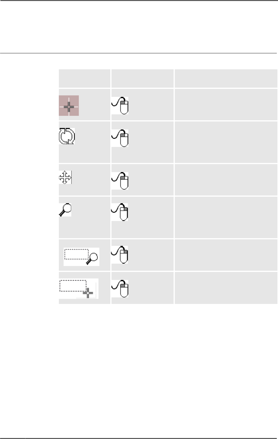
1 Introduction
1.3.10. Using a mouse
3HAC032104-001 Revision: D54
© Copyright 2008-2010 ABB. All rights reserved.
1.3.10. Using a mouse
Navigating the graphics window using the mouse
The table below shows how to navigate the graphics window using the mouse:
To
Use the keyboard /
mouse combination
Description
Select items
xx0500002417 xx0500002421
Just click the item to select. To select
multiple items, press CTRL key while
clicking new items.
Rotate the station
xx0500002424
CTRL + SHIFT +
xx0500002421
Press CTRL + SHIFT + the left mouse
button while dragging the mouse to rotate
the station.
With a 3-button mouse you can use the
middle and right buttons, instead of the
keyboard combination.
Pan the station
xx0500002422
CTRL +
xx0500002421
Press CTRL + the left mouse button while
dragging the mouse to pan the station.
Zoom the station
xx0500002426
CTRL +
xx0500002423
Press CTRL + the right mouse button while
dragging the mouse to the left to zoom out.
Dragging to the right zooms in.
With a 3-button mouse you can also use
the middle button, instead of the keyboard
combination.
Zoom using window
xx0500002425
SHIFT +
xx0500002423
Press SHIFT + the right mouse button
while dragging the mouse across the area
to zoom into.
Select using window
xx0500002428
SHIFT +
xx0500002421
Press SHIFT + the left mouse button while
dragging the mouse across the area to
select all items that match the current
selection level.

1 Introduction
1.3.11. Selecting an item
553HAC032104-001 Revision: D
© Copyright 2008-2010 ABB. All rights reserved.
1.3.11. Selecting an item
Overview
Each item in a station can be moved to achieve the required layout, so you first have to
determine its selection level. The selection level makes it possible to select only specific types
of items, or specified parts of objects.
The selection levels are curve, surface, entity, part, mechanism, group, target/frame and path.
The target/frame and path selection can be combined with any of the other selection levels.
Objects may also be grouped together as component groups, see Component Group on page
234.
Selecting an item in the graphics window
To select items in the graphics window, follow these steps:
1. At the top of the graphics window, click the desired selection level icon.
2. Optionally, click the desired snap mode icon for the part of the item you wish to select.
3. In the graphics window, click the item. The selected item will be highlighted.
Multiple selection of items in the graphics window
To select multiple items in the graphics window, do the following:
1. Press the SHIFT key, and in the graphics window drag the mouse diagonally over the
objects to select.
Selecting an item in the browsers
To select items in a browser, do the following:
1. Click the item. The selected item will be highlighted in the browser.
Multiple selection of items in the browsers
To select multiple items in a browser, follow these steps:
1. Make sure that all the items to be selected are of the same type and located in the same
branch of the hierarchical structure; otherwise, the items will not be operable.
2. Do one of the following:
• To select adjacent items: In the browser, hold down the SHIFT key and click the first
and then the last item. The list of items will be highlighted.
• To select separate items: In the browser, hold down the CTRL key and click the items
you want to select. The items will be highlighted.

1 Introduction
1.3.12. Attaching and detaching objects
3HAC032104-001 Revision: D56
© Copyright 2008-2010 ABB. All rights reserved.
1.3.12. Attaching and detaching objects
Overview
You can attach an object (child) to another object (parent). Attachments can be created on part
level and on mechanism level. When an object has been attached to a parent, moving the
parent also moves the child.
One of the most common attachments is to attach a tool to a robot. For procedures, see Attach
to on page 378 and Detach on page 385.
1 Introduction
1.3.13. Keyboard shortcuts
573HAC032104-001 Revision: D
© Copyright 2008-2010 ABB. All rights reserved.
1.3.13. Keyboard shortcuts
Keyboard shortcuts
The following table lists the keyboard shortcuts.:
Command Key Combination
General
Activate menu bar F10
Open API Help ALT + F1
Open Help F1
Open Virtual FlexPendant CTRL + F5
Switch between windows CTRL + TAB
General Commands
Add Controller System F4
Open Station CTRL + O
Take Screenshot CTRL + B
Teach Move Instruction CTRL + SHIFT + R
Teach Target CTRL + R
Toggle View Representation F7
General Editing
Copy CTRL + C
Cut CTRL + X
Paste CTRL + V
Redo CTRL + Y
Refresh F5
Rename F2
Select All CTRL + A
Undo CTRL + Z
Import Geometry CTRL + G
Import Library CTRL + J
New Station CTRL + N
Save Station CTRL + S
Program Editor Intellisense
Complete Word CTRL + SPACEBAR
Parameter Info CTRL + I
PickList CTRL + SHIFT + SPACEBAR
Program Editor Commands
Start Program Execution F8
Step In F11
Step Out SHIFT + F11
Step Over F12
Stop SHIFT + F8
Continues on next page

1 Introduction
1.3.13. Keyboard shortcuts
3HAC032104-001 Revision: D58
© Copyright 2008-2010 ABB. All rights reserved.
Toggle Breakpoint F9
Apply Changes CTRL + SHIFT + S
Print CTRL + P
Program Editor Hotkeys
Copy CTRL + Insert
Cut SHIFT + Delete
Cut marked lines CTRL + L
Delete marked lines CTRL + SHIFT + L
Delete to beginning of word CTRL + BACKSPACE
Delete to end of word CTRL + Delete
Indent Tab
Make the selected text lowercase CTRL + U
Make the selected text uppercase CTRL + SHIFT + U
Move to beginning of document CTRL + Home
Move to beginning of line Home
Move to end of document CTRL + End
Move to end of line End
Move to next word CTRL + Right
Move to previous word CTRL + Left
Move to visible bottom CTRL + Page Down
Move to visible top CTRL + Page Up
Open line above CTRL + Enter
Open line below CTRL + SHIFT + Enter
Outdent SHIFT + TAB
Paste SHIFT + Insert
Redo CTRL + SHIFT + Z
Scroll down CTRL + Down
Scroll up CTRL + Up
Select block down ALT + SHIFT + Down
Select block left ALT + SHIFT + Left
Select block right ALT + SHIFT + Right
Select block to next word CTRL + ALT + SHIFT + Right
Select block to previous word CTRL + ALT + SHIFT + Left
Select block up ALT + SHIFT + Up
Select down SHIFT + Down
Select left SHIFT + Left
Select page down SHIFT + Page Down
Select page up SHIFT + Page Up
Select right SHIFT + Right
Select to beginning of document CTRL + SHIFT + Home
Select to beginning of line SHIFT + Home
Select to end of document CTRL + SHIFT + End
Command Key Combination
Continued
Continues on next page

1 Introduction
1.3.13. Keyboard shortcuts
593HAC032104-001 Revision: D
© Copyright 2008-2010 ABB. All rights reserved.
Select to end of line SHIFT + End
Select to next word CTRL + SHIFT + Right
Select to previous word CTRL + SHIFT + Left
Select to visible bottom CTRL + SHIFT + Page Down
Select to visible top CTRL + SHIFT + Page Up
Select up SHIFT + Up
Select word CTRL + SHIFT + W
Toggle overwrite mode Insert
Transpose characters CTRL + T
Transpose lines CTRL + ALT + SHIFT + T
Transpose words CTRL + SHIFT + T
Command Key Combination
Continued

1 Introduction
1.3.13. Keyboard shortcuts
3HAC032104-001 Revision: D60
© Copyright 2008-2010 ABB. All rights reserved.

2
How
t
2.1. Workflow for building a new station
613HAC032104-001 Revision: D
© Copyright 2008-2010 ABB. All rights reserved.
2 How to build stations
2.1. Workflow for building a new station
Overview
This is an overview of how to build a station by including the equipment necessary to create
and simulate robot programs.
The first part of this overview describes the alternatives for creating a station with a system.
The second part describes importing or creating the objects to work with. The third part
describes the workflow for optimizing the station layout by finding the best placement of
robots and other equipment.
In most cases, following the workflows from start to finish is recommended, even if other
sequences are also possible.
Creating a station with a system
The table below shows the alternatives for creating a station with a system.
For procedures, see New Station on page 176.
Manually starting the VC
The table below shows the alternatives for manually starting with a system. Perform only
those steps applicable to your station.
Activity Description
Create a station with a
template system
This is the simplest way to create a new station containing a
robot and a link to a rudimentary system template.
Create a station with an
existing system
This creates a new station containing one or more robots in
accordance with an existing, built system.
Create a station with no
system
An advanced user can build a station from scratch and then add
a new or existing system to it.
Activity Description
Manually connecting a
library to the VC
See Starting a VC on page 71.
Restarting the VC See Restarting a VC on page 73.
Continues on next page

2 How to build stations
2.1. Workflow for building a new station
3HAC032104-001 Revision: D62
© Copyright 2008-2010 ABB. All rights reserved.
Importing station components
The table below shows the workflow for importing station components. Perform only those
steps applicable to your station.
For procedures, see Importing a station component on page 75.
Placing objects and mechanisms
The table below shows the workflow for placing the objects in the station.
Activity Description
Import a robot model See Robot System on page 192.
Import a tool See Import Library on page 191.
Import a positioner See ABB Library on page 190.
Import a track See Import Library on page 191.
Import other equipment If you have CAD models of the equipment, you can import them,
see Import Library on page 191. Otherwise, you can create
models in RobotStudio, see Mechanisms on page 82.
Add work piece If you have CAD models of the work piece, you can import them,
see Workobject on page 199. Otherwise, you can create models
in RobotStudio, see Objects on page 80.
Activity Description
Place objects If you are building a model of a real station, start by placing all
objects with known positions. For objects without known
positions, find a suitable placement, see Placing objects on
page 85 and Placing external axes on page 86.
Attach tools Attach the tools to the robot, see Attach to on page 378.
Attach robots to tracks If track external axes are used, attach the robots to the tracks,
see Attach to on page 378.
Attach work pieces to
positioners
If positioner external axes are used, attach the work pieces to
the positioners, see Attach to on page 378.
Test reachability Test if the robot can reach critical positions on the work piece. If
you are satisfied with how the robot reaches the positions, your
station is ready for programming. Otherwise, continue adjusting
the placement or trying other equipment as described below,
see Testing positions and motions on page 108.
Continued

2 How to build stations
2.2.1. Two robot systems sharing the same task frame position
633HAC032104-001 Revision: D
© Copyright 2008-2010 ABB. All rights reserved.
2.2 Setting up a conveyor tracking station with two robots working on the same
conveyor
2.2.1. Two robot systems sharing the same task frame position
Overview
This section describes what happens when both the robot systems share the same task frame
position. The baseframes of the mechanical units in both the robot systems have the same task
frame position.
Prerequisite
• Two robot systems with conveyor tracking option (system 1 and system 2)
• A conveyor mechanism saved as library
NOTE! See Create Conveyor mechanism on page 287 to create conveyor tracking systems.
Setting up the conveyor tracking station
1. Add the existing system (system 1) to the station. See Robot System on page 192.
NOTE! After starting the system, when asked to select the library, browse and select the
already saved conveyor mechanism library.
2. Modify the baseframe positions of conveyor and robot.
1. Move the mechanical unit (conveyor/robot) to its new location.
2. See Updating the baseframe position on page 370 to update the baseframe position of
the conveyor/robot.
3. Repeat steps 1 and 2to modify the baseframe position of the robot.
4. In the System Configuration window, click OK. When asked if you want to restart
the system, answer Ye s. Close the System Configuration window.
3. Add the existing system (system 2) to the station. See Robot System on page 192.
NOTE! After starting the system, when asked to select the library, browse and select the
same library as the one selected for system 1 or any other library. Later, this conveyor
library will be removed from the station since system 2 shall use the same conveyor
library as system 1.
4. Refer both systems (system 1 and system 2) to the same conveyor library.
1. In the Offline browser, click System Configuration to bring up a dialog box for
system 2.
2. Select the library node in the hierarchical tree.
3. Select the option Select from Station. Click Change. The Select Library dialog box
appears.
4. Select the same conveyor library as the one selected for system 1. Click OK.
Continues on next page

2 How to build stations
2.2.1. Two robot systems sharing the same task frame position
3HAC032104-001 Revision: D64
© Copyright 2008-2010 ABB. All rights reserved.
NOTE! Now both systems (system 1 and system 2) use the same conveyor library and the
library previously referenced by system 2 is removed from the station.
5. Modify the baseframe positions of robot (system 2).
1. Move the mechanical unit (robot) to its new location.
2. See Updating the baseframe position on page 370to update the baseframe position of
the robot.
3. Repeat steps 1 and 2 to modify the baseframe position of the robot.
4. In the System Configuration window, click OK. When asked if you want to restart
the system, answer Yes . Close the System Configuration window.
Continued

2 How to build stations
2.2.2. Two robot systems having different task frame positions
653HAC032104-001 Revision: D
© Copyright 2008-2010 ABB. All rights reserved.
2.2.2. Two robot systems having different task frame positions
Overview
This section describes what happens when two robot systems have different task frame
positions but uses the same sync switch. This means the Baseframes of the conveyor
mechanical units in both the robot systems have different values.
Prerequisites
Two robot systems with conveyor tracking option (system 1 and system 2)
NOTE! See Create Conveyor mechanism on page 287 to create conveyor tracking systems.
Setting up the conveyor tracking station
1. Add the existing system (system 1) to the station. See Robot System on page 192.
NOTE! After starting the system, when asked to select the library, browse and select the
already saved conveyor mechanism library.
2. Modify the baseframe positions of conveyor and robot.
1. Move the mechanical unit (conveyor/robot) to its new location.
2. See Updating the baseframe position on page 370 to update the baseframe position of
the conveyor/robot.
3. Repeat steps 1 and 2 to modify the baseframe position of the robot.
4. In the System Configuration window, click OK. When asked if you want to restart
the system, answer Ye s. Close the System Configuration window.
3. Add the existing system (system 2) to the station. See Robot System on page 192.
NOTE! After starting the system, when asked to select the library, browse and select the
same library as the one selected for system 1 or any other library. Later, this conveyor
library will be removed from the station since system 2 shall use the same conveyor
library as system 1.
4. Update both systems (system 1 and system 2) to use the same conveyor library.
1. In the Offline browser, click System Configuration to bring up a dialog box for
system 2.
2. Select the library node in the hierarchical tree.
3. Select the option Select from Station. Click Change. The Select Library dialog box
appears.
4. Select the same conveyor library as the one selected for system 1. Click OK.
NOTE! Now both systems (system 1 and system 2) use the same conveyor library and the
library previously referenced by system 2 is removed from the station.
5. Modify the task frame position of the conveyor mechanism. See Set Task Frames on page
369.
NOTE! Before modifying the task frame, make a note of the current conveyor position in
world coordinates. After modifying the task frame, move the conveyor back to the
position it was before modifying the task frame.
Continues on next page

2 How to build stations
2.2.2. Two robot systems having different task frame positions
3HAC032104-001 Revision: D66
© Copyright 2008-2010 ABB. All rights reserved.
6. Modify the baseframe positions of robot (system 2).
Repeat step 2 to modify the baseframe position of the robot (system 2)
1. Move the mechanical unit (robot) to its new location.
2. See Updating the baseframe position on page 370 to update the baseframe position of
the robot.
3. Repeat steps 1 and 2 to modify the baseframe position of the robot.
4. In the System Configuration window, click OK. When asked if you want to restart
the system, answer Yes . Close the System Configuration window.
7. Modify the baseframe position of the conveyor (system 2).
1. In the Offline browser, click System Configuration to bring up a dialog box for
system 2.
2. Select the conveyor in the hierarchical tree. The BaseFrame property list for the
conveyor is now displayed.
3. Select the option Use Current Station Values to update the baseframe value of the
robot in the controller.
4. Deselect the option Check BaseFrame on Startup.
5. In the System Configuration window, click OK. When asked if you want to restart
the system, answer Yes .
NOTE! By deselecting the option Check BaseFrame on Startup, RobotStudio will not
compare the BaseFrame values in the station and the controller every time the controller
is started. This avoids repositioning the conveyor library.
NOTE! If the two robot systems use the same part on the conveyor, the relation between
the part and the two conveyor workobjects should be the same.
Continued

2 How to build stations
2.3. Creating a system with external axes automatically
673HAC032104-001 Revision: D
© Copyright 2008-2010 ABB. All rights reserved.
2.3. Creating a system with external axes automatically
Automatically create a system with external axes
1. Import the desired robots, positioners, and track libraries into the RobotStudio station. See
Import Library on page 191.
NOTE! If a robot and track are selected, attach the robot to the track. See Attach to on
page 378.
NOTE!
Robot system supports the following tracks with lengths 1.7 m to 19.7 m in a separate task
or same robot task. Depending on the manipulator type, the system allows one to three
tracks per task. However with IRBTx004, only one track of this type can be used per
system.
• IRBT4003
• IRBT4004
• IRBT6003
• IRBT6004
• IRBT7003
• IRBT7004
• RTT_Bobin
• RTT_Marathon
• Paint Rail
2. Create a robot system from layout. See Robot System on page 192.
NOTE!
To create a robot system with IRBT4004, IRBT6004, or IRBT7004, the TrackMotion
mediapool must be installed. For more information, see Installing and Licensing
RobotStudio on page 30.
Continues on next page

2 How to build stations
2.3. Creating a system with external axes automatically
3HAC032104-001 Revision: D68
© Copyright 2008-2010 ABB. All rights reserved.
Supported external axes configuration
The following table shows a combination of different external axes configurations:
• Y - Combination is supported
• N - Combination is not supported
• YX - Combination is supported and manual mapping of mechanical units and joints
required
NOTE!
Creating a system from layout only supports tracks of type RTT and IRBTx003 in
combination with positioners. i.e. IRBTx004 is not supported in combination with the
positioners.
Manual mapping of mechanical units and joints
If the system contains more than one mechanical unit, the number of tasks and base frame
positions of the mechanism should be verified in the System Configuration.
1. In the Offline browser, click System Configuration to bring up a dialog box.
2. Select the robot from the node in the hierarchical tree.
The property page of this node contains controls for mapping and setting axes and joints.
3. Click Change to open a dialog box.
4. Manually map the mechanical unit and mechanism joints. Click Apply.
5. Modify the baseframe positions of the mechanical unit. See Updating the baseframe
position on page 370.
Combination
Positioner type
A B C D K L 2xL R
One IRB (Positioner in
same task)
Y Y Y Y Y Y Y Y
One IRB (Positioner in
separate task)
Y Y Y Y Y Y Y Y
Two IRB (Positioner in
separate task)
Y Y Y Y Y Y N Y
One IRB on Track Motion
(Positioner in same task)
Y N N N YX Y Y N
One IRB on Track Motion
(Positioner in separate task)
Y N N N YX Y Y N
Two IRB on Track Motion
(Positioner in separate task)
Y N N N YX Y N N
Continued

2 How to build stations
2.4.1. Setting up a system with track motion of type RTT or IRBTx003 manually
693HAC032104-001 Revision: D
© Copyright 2008-2010 ABB. All rights reserved.
2.4 Manually setting up a system with track motion
2.4.1. Setting up a system with track motion of type RTT or IRBTx003 manually
Manually set up a system with track motion of type RTT or IRBTx003
Use this procedure to manually set up a system with track motion type RTT Bobin, RTT
Marathon or IRBT4003, IRBT6003, or IRBT7003.
1. Build and start a new system. See Building a new system on page 148.
2. Add the system to the station. See Adding a system on page 72
3. Add the corresponding track configuration file of the desired robot variant (IRB 6600) and
the desired track model to the station. See Adding the track to the system on page 75.
NOTE! In the Select Library group, select either the existing track or import a different
track.
NOTE! The system may fail unless the correct additional axes configuration is selected.
4. Specify whether the baseframe is moved by another mechanism.
1. In the Offline browser, click System Configuration to bring up a dialog box.
2. Select ROB_1 node from the hierarchical tree.
3. Select the option Track from the BaseFrame moved by list.
4. Click OK. When asked if you want to restart the system, answer Ye s. Close the
System Configuration window.
Action Description
1 Select the desired robot variant
(IRB6600).
In the New Controller System wizard of the
System Builder, naviagte to Modify Options
page and scroll down to Drive Module 1 > Drive
module application group and expand ABB
Standard manipulator option and select
Manipulator type (IRB6600).
2 Select the Additional axes
configuration.
In the New Controller System wizard of the
System Builder, naviagte to Modify Options
page of the System Builder, scroll down to Drive
Module 1> Additional axes configuration group
and expand the Add axes IRB/drive module
6600 option and select the 770-4 Drive W in pos
Y2 option.
NOTE! The option 770-4 Drive W in pos Y2, the
Drive module, and the Position varies depending
on the Additional axes configuration selected.
Make sure to select at least one drive in any
position.
3 Click Finish. Close the Modify Options page.

2 How to build stations
2.4.2. Setting up a system with track motion of type IRBTx004 manually
3HAC032104-001 Revision: D70
© Copyright 2008-2010 ABB. All rights reserved.
2.4.2. Setting up a system with track motion of type IRBTx004 manually
Overview
For configuration of tracks of type IRBT4004, IRBT6004, or IRBT7004, the TrackMotion
mediapool must be installed. For more information, see Installing and Licensing RobotStudio
on page 30.
Manually set up a system with track motion of type IRBTx004
1. Build and start a new system. See Building a new system on page 148.
2. Add the system to the station. See Adding a system on page 72.
3. Add the desired track model to the station. See Adding the track to the system on page 75.
NOTE!
1. In the Select Library group, click Other to import a different track motion library.
2. Click OK. When asked if you want to restart the system, answer Ye s. Close the
System Configuration window.
Action Description
1 Add additional options for
IRBTx004.
See Adding additional options on page 149.
NOTE! Browse and select the key file (.kxt)
located in the mediapool Track 5.XX.YYYY where
5.XX indicates the latest RobotWare version being
used.
2 Select the desired robot variant
(IRB6600).
On the Modify Options page of the System
Builder, scroll down to Drive Module 1 > Drive
module application group and expand ABB
Standard manipulator option and select
Manipulator type (IRB6600).
3 Select Additional axes configura-
tion.
On the Modify Options page of the System
Builder, scroll down to Drive Module 1>
Additional axes configuratin group and expand
the Add axes IRB/drive module 6600 option and
select the 770-4 Drive W in pos Y2 option.
NOTE! The option 770-4 Drive W in pos Y2, the
Drive module, and the Position varies
depending on the Additional axes configuration
selected. Make sure to select at least one drive in
any position.
4 Select the desired track motion
(IRBT 6004).
On the Modify Options page of the System
Builder, scroll down to the TRACK and expand
the Drive module for Track motion group. Select
Drive Module 1 >Track Motion type > IRBT
6004 > Irb Orientation on Track > Standard
carriage In Line > Select Track Motion Length
> 1.7m (or any other variant).
5 Click Finish. Close the Modify Options page.

2 How to build stations
2.5.1. Starting a VC
713HAC032104-001 Revision: D
© Copyright 2008-2010 ABB. All rights reserved.
2.5 The VC
2.5.1. Starting a VC
Overview
RobotStudio uses virtual controllers for running the robots. Virtual controllers can run both
systems for real robots and specific virtual systems for testing and evaluation purposes. A
virtual controller uses the same software as the controller to execute the RAPID program, to
calculate robot motions and to handle I/O signals.
When starting a virtual controller, point out which system to run on it. Since the system
contains information about the robots to use and important data such as robot programs and
configurations, it is important to select the right system for the station.
Starting a VC
The table below describes the different ways a virtual controller may start:
Startup Description
Automatic, when creating a
station
In most cases, a VC is automatically started when you create a
new station. Library files for the robots used by the system are
then imported to the station.
Automatic, when adding a
system to an existing
station
If your station uses several systems or if you started with an
empty station, you can add systems to an open station. Library
files for the robots used by the the systems are then imported to
the station.
Manually, when connecting
to an imported library
If you have manually imported a robot library you want to use
with a system, instead of importing a new library at startup, you
can connect this library to a controller.
If you have manually imported a robot library you want to use
with a system, instead of importing a new library at startup, you
can connect this library to a controller.
A library may only be connected to a single-robot system and
may not be already connected to another VC.
Continues on next page

2 How to build stations
2.5.1. Starting a VC
3HAC032104-001 Revision: D72
© Copyright 2008-2010 ABB. All rights reserved.
Adding a system
To start a system in a new virtual controller and automatically import the robots used by the
system, follow these steps:
1. • If you have the Select system dialog box open, continue with the next step.
• If you do not have the Select system dialog box open, go to the Controller menu and
click Add System.
2. Depending on whether the system to start on the virtual controller is ready or not, do one
of the following:
3. From the Systems Found list, select the system to use and click Start.
Activity Description
Create and start a copy of an existing
system
This is recommended when you plan to add
station-specific configurations or programs.
From the Select system pool list, select the
folder on your PC that contains the system to
use. Select the system to copy from the
Systems Found list and click Copy. In the
Copy System dialog box, enter a name for
the system and click OK.
Start an existing system as is
This is useful when you already have created
a specific system for the station.
It is also useful if you do not plan to create
station-specific configurations or programs
and want a quick start.
From the Select system pool list, select the
folder on your PC that contains the system to
use.
Modify and start an existing system
This is the way to add or change options in
the systems, for example, adding or replacing
robots and external axes.
From the Select system pool list, select the
folder on your PC that contains the system to
modify. Select the system to modify from the
Systems Found list and click Modify. This
starts the System Builder from which you
make the modifications. For detailed informa-
tion, see Modifying a system on page 152.
Build and start a new system
This option is used for building and starting a
completely new system, either from
RobotWare keys or from virtual keys.
Click Create to start the System Builder
from which you build the new system. For
detailed information about creating the
system, see Building a new system on page
148.
Continued

2 How to build stations
2.5.2. Restarting a VC
733HAC032104-001 Revision: D
© Copyright 2008-2010 ABB. All rights reserved.
2.5.2. Restarting a VC
Overview
This section describes when and how to restart a VC in RobotStudio. See also Restart on page
330.
Prerequisites
The following are the prerequisites for restarting a controller:
• You must have Write access to the controller you are restarting.
• For the advanced restart methods X-start and C-start, you must have access to the
controller's FlexPendant.
When to restart a virtual controller
Some operations require a restart of the controller to take effect. When working in
RobotStudio, you will be notified when a restart is necessary.
Warm restart
Typically, you need to make an ordinary warm restart of a virtual controller when:
• you have changed the baseframe of any of the robots belonging to that virtual
controller.
• you have changed the robot's configuration, either with the Configuration Editor or by
loading new configuration files.
• you have added new options or hardware to the system.
• A system failure has occurred.
Cold restart
A cold restart is useful for restoring the system running on a virtual controller to the state it
was created in. The cold restart deletes all RAPID programs, data and custom configurations
that have been added to the system.
Advanced restarts
In addition to warm and cold restarts, several advanced restarts are available. See Advanced
restart options on page 74.
Continues on next page

2 How to build stations
2.5.2. Restarting a VC
3HAC032104-001 Revision: D74
© Copyright 2008-2010 ABB. All rights reserved.
Advanced restart options
The controller can be restarted with the following advanced restart options:
Option Description
I-Start Restarts the controller with the current system and the default
settings.
This method discards the changes made to the robot's configu-
ration. It reverts the current system to the state it had when it
was installed on the controller (an empty system).
P-Start Restart the controller with the current system and reinstall
RAPID.
This method deletes all RAPID program modules. It can be
useful if the system has changed in such a way that the
programs no longer are valid, for instance if system parameters
used by the program are changed.
X-Start Saves the current system and starts the boot application.
This method saves the current system, with the current settings,
and starts the boot application from which you can choose a
new system to start with. You can also configure the controller's
network settings from the boot application.
C-Start Deletes current system and starts the boot application.
This method deletes the current system and starts the boot
application from which you can choose a new system to start
with. You can also configure the controller's network settings
from the boot application.
B-Start Restarts the controller with the current system and the last
known good settings.This method restores changes made to
the robot's configuration to a previously good state.
Continued

2 How to build stations
2.6.1. Importing a station component
753HAC032104-001 Revision: D
© Copyright 2008-2010 ABB. All rights reserved.
2.6 Station components
2.6.1. Importing a station component
Importing a robot model
This is how to import a robot model without a controller to your station.
A robot which is not connected to a controller cannot be programed. To import a robot
connected to a virtual controller, configure a system for the robot and start it in a virtual
controller, see Building a new system on page 148 and Starting a VC on page 71, respectively.
To import a robot model, in the Home tab, click Robot System and then select a robot model
from the gallery.
Importing a tool
A tool is a special object, for example, an arc weld gun or a gripper, that operates on the work
piece. For achieving correct motions in robot programs, the parameters of the tool have to be
specified in the tool data. The most essential part of the tool data is the TCP, which is the
position of the tool center point relative to the wrist of the robot (which is the same as the
default tool, tool0).
When imported, the tool will not be related to the robot. So in order for the tool to move with
the robot, you must attach it to the robot.
To import a tool, in the Home tab, click Tool and then select a tool from the gallery.
Importing a positioner
To import a tool, in the Home tab, click Positioner and then select a positioner from the
gallery.
Adding the track to the system
To select the model of the external axis to use, follow these steps:
NOTE!
This procedure is not applicable for a robot system with track motions IRBT4004, IRBT6004,
or IRBT7004. They are configured by the TrackMotion mediapool and not by adding
separate configuration files. For information on installation instructions, see Installing and
Licensing RobotStudio on page 30.
1. Start the system in a virtual controller, either in a new empty station or in an existing
station, see Robot System on page 192.
2. In the Layout browser, select the system to add the track to.
3. On the Offline tab, click System Configuration.
Continues on next page

2 How to build stations
2.6.1. Importing a station component
3HAC032104-001 Revision: D76
© Copyright 2008-2010 ABB. All rights reserved.
4. Click Add to add parameters for the track to the system. Browse to the parameter file
(.cfg) for the track to add and click Open.
If you have a specific parameter file for you track, use that one. Otherwise, parameter files
for some standard tracks are delivered with the RobotStudio installation. These can be
found in the folder ABB Library/ Tracks in RobotStudio’s installation folder. The ABB
Library folder can also be opened from the Quick access pane at the left of the Open
dialog box used for adding parameter files.
The file name of each parameter file tells which tracks it supports. The first part tells the
length of the track and the second the number of tasks.
For example, the file TRACK_1_7.cfg supports all tracks with the length 1.7 meters in
systems with one single task. For Multimove systems or other systems with several tasks,
use the configuration file with the matching number of tasks.
For example, if the track length is 19.9 m and the robot attached to the track is connected
to task 4 of the MultiMove system, then select TRACK_19_9_Task4.cfg file.
5. In the System Configuration window, click OK. When asked if you want to restart the
system, answer Yes .
6. During the restart a list of all tracks compatible with the configuration file is displayed.
Select the one to use and click OK.
After the restart the track appears in the station. Continue with attaching the robot to the
track.
Importing a library, geometry or piece of equipment
A library component is a RobotStudio object that has been saved separately. Normally,
components in a library are locked for editing.
A geometry is CAD data which you can import to use in RobotStudio. For a list of importable
CAD formats, see Libraries, geometries and CAD files on page 26.
To import a library, geometry or piece of equipment, see Import Library on page 191.
Continued

2 How to build stations
2.6.2. Converting CAD formats
773HAC032104-001 Revision: D
© Copyright 2008-2010 ABB. All rights reserved.
2.6.2. Converting CAD formats
Overview
A CAD converter is installed together with RobotStudio by default. In most cases you do not
have to convert CAD files before importing them to RobotStudio, but the CAD converter
might be useful for converting several files at once, or for converting with custom settings.
Prerequisites
Most of the file formats require separate licenses, see Libraries, geometries and CAD files on
page 26 for more information.
Starting the CAD converter
Click Start menu, point to Programs, ABB Industrial IT, Robotics IT and click CAD
Converter.
Converting CAD files
To convert CAD files, follow these steps:
1. Click Add files and select the files to convert. Optionally, click Add files, again to add
more files from another location.
Each file is now added to a row in the grid.
2. Optionally, change the suggested file name or target format by clicking that column for
the file to change.
3. In the Target directory box, specify the folder in which to save the new files.
4. Optionally, click Settings and change the settings for the conversion. For details about the
conversion settings, see Conversion settings on page 77.
5. Click Convert Files.
Conversion settings
The table below describes the settings for the conversion:
Setting Description
Acis save file format Select which version of ACIS to save to when using ACIS as
target format.
Enable Healing Controls whether the conversion engine attempts to heal
geometric entities. Only supported for specified formats.
Translate hidden/no-
show entities
Controls whether the hidden entities are translated or
discarded. Only supported for specified formats.
VRML/STL Scale factors VRML and STL are often created in units that RobotStudio does
not expect; they thus need to be resized.
Delete all generated log
files on exit
Makes the CAD converter delete log files when exiting.

2 How to build stations
2.6.3. Troubleshooting and optimizing geometries
3HAC032104-001 Revision: D78
© Copyright 2008-2010 ABB. All rights reserved.
2.6.3. Troubleshooting and optimizing geometries
Overview
The characteristics of the geometries and CAD models in the station may have great effect on
your work in RobotStudio, both in aspects of making the objects easier to program as well as
enhancing simulation performance.
Below are some guidelines for troubleshooting geometries.
Trouble Information
The pointer snaps to the
wrong parts of the objects
when selecting in the
graphics window
This problem might be caused by wrong snap mode settings,
imprecise selecting, hidden or lack of geometrical information.
To resolve these problems, do the following:
• Check the selection level and snap mode settings. For
more information, see Selecting an item on page 55.
• When making the selection, zoom and rotate the object
so that you are sure to click inside the object.
• Check if the object has hidden details that might affect
the snapping. Remove details that are not necessary for
your programming or simulation. For more information,
see Modifying a part on page 81.
• Some file formats only contain a graphical representa-
tion and no geometrical data. Import the geometry from
a file format that also contains geometrical data. For
more information, see Libraries, geometries and CAD
files on page 26.
The graphics window
redraws or updates slowly
This might be due to the performance of your computer not
being high enough for the size of the geometry files in your
station.
To reduce the size of the geometry files, do any of the following:
• Use a lower detail level for rendering the geometry. For
more information, see Graphic Appearance on page
387.
• Blends, chamfers and holes can be automatically
simplified by using the Defeature function. This can
greatly reduce graphic complexity, speed up simulations
and reduce memory usage.
• Check if the object has unnecessary details. Remove
details that are not necessary for your programming or
simulation. For more information, see Modifying a part
on page 81.
Continues on next page

2 How to build stations
2.6.3. Troubleshooting and optimizing geometries
793HAC032104-001 Revision: D
© Copyright 2008-2010 ABB. All rights reserved.
To invert the direction of all faces of a part
To invert the direction of all faces of a part, follow these steps:
1. Select the part on which faces you want to invert the directions.
2. On the Modify menu, click Graphic Appearance.
3. On the Rendering tab, click Flip normals and then click OK.
To deactivate backface culling for a single object
To change the backface culling setting for a single object, follow these steps:
1. Select the part for which you want to change the backface culling setting.
2. On the Modify menu, click Graphic Appearance.
3. On the Rendering tab, clear the Backface culling check box and then click OK. The
faces of the object will now be displayed even if the generic setting for backface culling
is on.
To change the generic setting for backface culling
The generic setting for backface culling affects all new objects and existing objects that do
not have backface culling specifically deactivated.
1. On the Application menu, click RobotStudio Options.
2. On the Navigation pane to the left, select Graphics: Performance.
3. On the Performance page, select or clear the Cull back-facing triangles check box and
then click OK.
Parts of the geometry are
not visible
If parts of the geometry are not visible from some views, a
probable cause is that the object is made up of 2D surfaces and
the option Backface culling is on.
Backface culling means that the faces of the object are only
visible from the front, and if the object (or any of its faces) is
oriented differently, they will not be visible.
To correct the problem, do one of the following:
• Switch to modeling mode and invert the direction of the
face that is not displayed correctly. This not only corrects
the display, it also decreases the chance of faulty orien-
tations during graphical programming. For more informa-
tion, see Invert on page 390 or To invert the direction of
all faces of a part on page 79.
• Turn backface culling off for the specific object. This
makes the object display correctly, but does not affect
the direction of the face, which might cause problems if
the face will be used for graphical programming. For
more information, see To deactivate backface culling for
a single object on page 79.
• Turn backface culling off for all objects in the station. This
makes the objects display correctly, but does not affect
the direction of the face, which might cause problems if
the face will be used for graphical programming. It also
decreases the performance of the graphic handling. For
more information, see To change the generic setting for
backface culling on page 79.
Trouble Information
Continued

2 How to build stations
2.7.1. Objects
3HAC032104-001 Revision: D80
© Copyright 2008-2010 ABB. All rights reserved.
2.7 Modeling
2.7.1. Objects
Overview
This section describes how to create or modify geometrical objects.
Creating a frame
A frame is a generic coordinate system that you can use as reference when positioning
objects. Generic frames can also be converted to special kinds of coordinate systesm, like
workobjects or tool center points.
For procedures, see Frame on page 196 and Frame from Three Points on page 197.
Creating a solid
With the create solids commands you can create and build models of objects you do not have
CAD files or libraries for. With the create solids commands you create primitve solid bodies;
these can later be combined to more complex bodies.
For procedures, see Solid on page 268.
Creating a surface
For procedures, see Surface on page 272.
Creating a curve
When creating paths with targets based on the object geometries, curves are the geometrical
objects that RobotStudio uses. For example, if you want the robot to run along the edge of an
object, you can first create a curve along the border and then generate a complete path along
that curve, instead of manually finding and creating the necessary targets.
If the CAD model/geometry of the work piece does not already contain curves, you can create
the curves i RobotStudio.
For procedures, see Curve on page 274.
Modifying a curve
When creating paths with targets based on the objects geometries, curves are the geometrical
objects that RobotStudio uses. By optimizing the curves before starting programming, you
reduce the touch-up of the generated paths.
For procedures, see Modify Curve on page 399.
Creating a border
For procedures, see Border on page 279.
Creating a line from normal
A line can be created as a new part and body perpendicular to a surface.
For a procedure, see Line from Normal on page 285.
Continues on next page

2 How to build stations
2.7.1. Objects
813HAC032104-001 Revision: D
© Copyright 2008-2010 ABB. All rights reserved.
Extruding a surface or curve
Curves and surfaces and curves can also be extruded to 3D objects, which may then be
converted to solids. You can extrude along either a vector or a curve.
For procedures, see Extrude Surface or Curve on page 284.
Modifying a part
When you import a geometry or create an object, it will be one part. A part can, however,
contain several bodies. In RobotStudio’s modeling mode you can modify the parts by adding,
moving and deleting the bodies.
To modify a part, follow this step:
1. In the Modeling browser, expand the node for the part to modify. Then modify the part
by doing any of the following:
Modifying a library component
As external files, libraries are merely linked from a station. Therefore, to modify an imported
library component, the link must first be broken and later reestablished. For procedures, see
The Library Group on page 393.
To Do this
Delete a body Select the body and press the DEL key.
Move a body from one part
to another
Drag the body or use the Copy and Paste commands on the
Edit menu.
Move one body relative to
the others
Select the body and then move it using any of the ordinary
commands for moving objects, see Placing objects on page 85.
Continued

2 How to build stations
2.7.2. Mechanisms
3HAC032104-001 Revision: D82
© Copyright 2008-2010 ABB. All rights reserved.
2.7.2. Mechanisms
Workflow
This information topic describes how to create a new mechanism, that is, a graphical
representation of a robot, tool, external axis or device. The various parts of a mechanism
move along or around axes.
Creating a mechanism is dependent upon skillful construction of the main nodes of the tree
structure. Four of these—links, joints, frames/tools and calibration—are initially marked red.
As each node is configured with enough subnodes to make it valid, the marking turns to
green. As soon as all nodes have become valid, the mechanism will be considered compilable
and can be created. For additional validity criteria, see the table below.
The modify mode of the Mechanism Modeler has two purposes: to enable modification of an
editable mechanism in its tree structure, and to complete the modeling of a new or modified
mechanism.
It is recommended to configure each main node in the tree structure from the top down.
Depending on its current status, right-click or double-click a node or subnode to add, edit or
remove it.
For procedures, see Create Mechanism on page 287.
Node Validity critera
Links • It contains more than one subnode.
• The BaseLink is set.
• All link parts are still in the station.
Joints • At least one joint must be active and valid.
Frame/tool Data • At least one frame/tool data exists.
• For a device, no frames are needed.
Calibration • For a robot, exactly one calibration is required.
• For an external axis, one calibration is required for each
joint.
• For a tool or device, calibrations are accepted, but not
required.
Dependencies • None.

2 How to build stations
2.7.3. Tools and tooldata
833HAC032104-001 Revision: D
© Copyright 2008-2010 ABB. All rights reserved.
2.7.3. Tools and tooldata
Overview
To simulate the robot tool, you need tooldata for the tool. If you import a predefined tool or
if you create a tool using the Create Tool Wizard, the tooldata is automatically created;
otherwise, you have to create the tooldata yourself.
The tooldata simplifies the programming work with respect to the different tools that may
come in use. Defining separate sets of tooldata for different tools makes it possible to run the
same robot program with different tools: only the new tooldata has to be defined. The tooldata
contains the information required for moving and simulating the tool.
Two methods for manipulating tooldata in RobotStudio are as follows:
• Create or modify tooldata, see Tooldata on page 200 and Modify Tooldata on page
407, respectively. This will create all data necessary for programming, but there will
be no visual tool during the simulation.
• Create tooldata for an existing geometry, Create Tool on page 293.
Creating and setting up a stationary tool
This information topic describes how to create a stationary tool. For information about
creating a robot hold tool, see Create Tool on page 293.
Using a stationary tool, the robot holds and moves the work piece in relation to the tool. Thus,
both the tooldata and the workobject must be set up correctly.
To create the tooldata for a stationary tool, follow these steps:
1. Import the geometry or library that represents the tool, see Import Geometry on page 195.
If you do not have the geometry or library at hand but know the position, you can skip this
step. The tool will be programable, but not visible in the station.
2. Create the tooldata for the tool, see Tooldata on page 200.
Make sure to set the Robot holds tool option to false.
3. Create a workobject that is moved by the robot. see Workobject on page 199.
Make sure to set the Robot holds workobject option to true.
4. If you have a geometry or library component for the work piece, attach it to the robot, see
Attach to on page 378.

2 How to build stations
2.7.4. Setting the local origin of an object
3HAC032104-001 Revision: D84
© Copyright 2008-2010 ABB. All rights reserved.
2.7.4. Setting the local origin of an object
Overview
Each object has a coordinate system of its own called local coordinate system in which the
object dimensions are defined. When the object’s position is referred from other coordinate
system, it is the origin of this coordinate system that is used.
With the Set Local Origin command you reposition the object’s local coordinate system, not
the object itself.
For a procedure, see Set Local Origin on page 419.
2 How to build stations
2.8.1. Placing objects
853HAC032104-001 Revision: D
© Copyright 2008-2010 ABB. All rights reserved.
2.8 Placement
2.8.1. Placing objects
Overview
To achieve the required layout of your station, you need to import or create objects, place
them accordingly and, if applicable, attach them to other objects.
Placing objects means setting their position and rotation. If the objects are to be attached to
robots or other mechanisms, they will be placed at their attachment point automatically.
The following table describes the actions relating to placement:
Actions Description
Placing an object To place an object is to put the object in the required position in
the station, see Place on page 411 and Set Position on page
421.
Rotating an object The objects in the station can be rotated to achieve the required
layout, see Rotate on page 417.
Measuring distance or
amgles
The measurement functions calculates distances, angles and
diameters between points you select from the graphics window.
When using measurements, results and instructions on how to
proceed are displayed in the Output window, see The Measure
Group on page 286.
Creating a component
group
A component group groups related object in the browser, see
Component Group on page 234.
Attaching or detaching
an object
Objects that are to be used by the robots in any way, such as
tools, need to be attached to the robot, see Attach to on page
378 and Detach on page 385.
Jogging a robot Robots can be placed by jogging. The robot axes can also be
postioned by jogging, see Jogging mechanisms on page 93.
Modifying the task frame Modifying the task frame repositions a controller and all its
robots and equipment in the station.
By default the controller world and the station world coordinate
system coincide. This is convenient when building a station with
one single controller. For a procedure, see Set Task Frames on
page 369.
However, when you have several controllers in one station, or
need to reposition a controller in an existing station, you need to
modify the System Configuration on page 370.
Modifying the baseframe
position
Modifying the baseframe position sets an offset between the
controller’s world coordinate system and the baseframe of the
mechanical unit.This is necessary when having several
mechanical units belonging to one controller, for example,
several robots in MultiMove systems or when using positioner
external axes. For a procedure, see System Configuration on
page 370.

2 How to build stations
2.8.2. Placing external axes
3HAC032104-001 Revision: D86
© Copyright 2008-2010 ABB. All rights reserved.
2.8.2. Placing external axes
Overview
When starting a system with a track or positioner external axis in a RobotStudio station, you
have to set up the system to load a model for the track or positioner and get the motions to
work properly.
Prerequisites
The system shall be created with support for track or positioner external axes, see A system
with support for one robot and one positioner external axis on page 162.
Attaching the robot to the track
To attach the robot to the track, follow these steps:
1. In the Layout browser, drag the robot icon and drop it on the track icon.
2. To the question Should the robot be coordinated with the track?, answer Ye s to be able
to coordinate the track’s position with that of the robot in robot programs. To program the
track and the robot independently, answer No.
3. When asked if you want to restart the system, answer Yes.
The track is now added to the system and ready to be programmed, see Programming
external axes on page 117 for more information on how to program the track.
CAUTION!
If the system is cold started , the setup is deleted and the procedures described here must be
performed again.
Placing the positioner in the station
To place the positioner in the station, follow these steps:
1. Move the positioner to the desired position using any of the ordinary functions for placing
and moving objects, see Placing objects on page 85.
2. Modify the baseframe position of each mechanical unit of the positioner except the
INTERCH unit, if it exists. When asked if you want to restart the system, answer Ye s.
After the restart the system is updated with the positioner’s new location. Continue
attaching fixtures and workobjects to the positioner.
Continues on next page

2 How to build stations
2.8.2. Placing external axes
873HAC032104-001 Revision: D
© Copyright 2008-2010 ABB. All rights reserved.
Attaching objects to the positioner
To program robot motions on an object that is held by the positioner, the targets must be
created in a workobject that is attached to the positioner. For a complete visual simulation,
CAD models that are moved by the positioner should also be attached. To attach the objects,
follow these steps:
1. Import the models of the fixture and the work piece if you do not have them in the station
already, see Importing a station component on page 75.
2. Attach the fixture to the positioner, see Attaching and detaching objects on page 56. When
asked whether to keep the current position, answer No.
If the positioner has several stations, you will be asked which one to attach the object to.
3. Attach the work piece to the fixture. When asked whether to keep the current position,
answer No.
4. Attach the workobject in which you will program the work piece to either the fixture, the
work piece or the positioner. If you have defined calibration positions on either the work
piece or the fixture, it is a good practice to use that object. When asked whether to keep
the current position, answer No.
The positioner is now set up and ready to be programed, see Programming external axes
on page 117 for more information.
TIP!
If the positioner is of an interchangeable type with several stations, you can either attach
individual fixtures, work pieces and workobjects to each station flange, or you can use one
set of objects that you attach and detach to the different flanges by events.
CAUTION!
If the system is cold started, the setup is deleted and the procedures described here must be
performed again.
Continued

2 How to build stations
2.8.3. Placing robots
3HAC032104-001 Revision: D88
© Copyright 2008-2010 ABB. All rights reserved.
2.8.3. Placing robots
Overview
When modifying the position of a robot connected to a VC there is a possibility to modify the
related task frame or any stationary RAPID objects (tooldata, workobjects) connected to the
robot.
Prerequisites
A robot library must be present in the station and connected to a VC, see Creating a station
with a system on page 61.
Modifying the robot position using a positioning tool
1. Modify the baseframe position of a robot connected to a VC using any of the following
options:
• Set Position. See Positioning an item on page 421.
• Place object by One Point, Two Points, Three Points, Frame, and Two Frames. See
Placing an item on page 411.
• Rotate. See Rotating an item on page 417.
2. Click Apply.
To the question, Do you also want to move the Task Frame?. Click Yes or No.
• Click Yes to move the task frame, but the base frame keeps its relative placement to
the task frame.
• Click No to move the base frame and the placement relative to the task frame will
change.
NOTE!
If there are any stationary RAPID objects (tooldata, workobjects) in the corresponding task,
the following question appears Do you want to keep the positioning of all stationary
RAPID objects?
• Click Yes to keep all the stationary RAPID objects in their global coordinates.
• Click No to move all the stationary RAPID objects along with the base frame (same
coordinates relative to base frame). Workobjects attached to any other object in the
station will not be affected. Workobjects attached to any other object in the station will
not be affected.
If the base frame configuration of the VC is updated, the VC has to be restarted for the
changes to take effect. i.e. if the base frame changes its placement relative to task frame, the
following question appears Do you want to update the controller configuration and
restart?
• Click Yes to restart the controller and update the base frame configuration of the
connected VC.
• Click No if the base frame is not in accordance with the controller.
Continues on next page

2 How to build stations
2.8.3. Placing robots
893HAC032104-001 Revision: D
© Copyright 2008-2010 ABB. All rights reserved.
Modifying the robot position using Freehand move or rotate
1. Modify the baseframe position of a robot connected to a VC using the following Freehand
options:
• Move. See Moving an item on page 225.
• Rotate. See Rotating an item on page 226.
For information on updating the robot baseframe, see Updating the baseframe position on
page 370.
2. A warning message is displayed in the Output window.
Continued

2 How to build stations
2.8.3. Placing robots
3HAC032104-001 Revision: D90
© Copyright 2008-2010 ABB. All rights reserved.

3 How to program robots
3.1. Workflow for programming a robot
913HAC032104-001 Revision: D
© Copyright 2008-2010 ABB. All rights reserved.
3 How to program robots
3.1. Workflow for programming a robot
Overview
In most cases, going through the workflow from start to finish is recommended, even if it
possible to work in other sequences as well.
Synchronizing will save and load text files containing RAPID modules, and create RAPID
programs from your station.
Prerequisites
Before creating a program for your robot, you should set up the station, including robots,
work pieces and fixtures, in which your robot will work.
Programming a robot
The table below describes the workflow for programming a robot to perform the task you
require.
Task Description
Create targets and paths Create the targets and paths the robot requires to perform the
work tasks.
To create targets and paths, do one of the following:
• Create a curve to match your required shape. Then use
the Create path from curve command to generate a
path, complete with targets, along the shape you have
created. See Curve on page 274 and Path from Curve on
page 208.
• Create targets at the requested positions, then create a
path and insert the created targets into it. See Create
Target on page 202, Teach Target on page 201 and
Empty Path on page 207.
Check the target orienta-
tions
Make sure that the targets are oriented in the most efficient way
for the tasks to be performed. If not, reorient the targets until you
are satisfied. See Orientations on page 99.
Check reachability Check that the robot and tool reach all targets in the path. See
Testing positions and motions on page 108.
Synchronize the program
to the virtual controller
Generates RAPID code from the RobotStudio items and
enables the program to be simulated.
Perform text-based
editing
If you need to edit the instructions or data created by RobotStu-
dio, you can start the Program Editor. See Using the RAPID
editor on page 121.
Collision detection Check that the robot or tool does not collide with the
surrounding equipment or the fixtures. If it does, adjust the
placements or orientations until no collisions occur. See
Detecting collisions on page 127.
Test the program Test the program by moving along the paths. See Testing
positions and motions on page 108.

3 How to program robots
3.2. Workobjects
3HAC032104-001 Revision: D92
© Copyright 2008-2010 ABB. All rights reserved.
3.2. Workobjects
Creating a workobject
A workobject is a coordinate system used to describe the position of a work piece. The
workobject consists of two frames: a user frame and an object frame. All programed positions
will be related to the object frame, which is related to the user frame, which is related to the
world coordinate system.
xx0500001519
For a procedure, see Workobject on page 199.
Modifying a workobject
For a procedure, see Modify Workobject on page 408.
Converting a frame to a workobject
You can create a new workobject from an existing frame. The converted workobject gets the
same name and position as the selected frame.
For a procedure, see Convert Frame to Workobject on page 382.
Creating a frame by points
You can create a frame by specfiying points on the axes of the coordinate system and letting
RobotStudio calulate the placement and orientation of the frame’s origin.
For a procedure, see Frame from Three Points on page 197.

3 How to program robots
3.3. Jogging mechanisms
933HAC032104-001 Revision: D
© Copyright 2008-2010 ABB. All rights reserved.
3.3. Jogging mechanisms
Jogging a robot
To check if the robot can reach all positions on the work piece, you can jog the TCP or the
joints of the robot, either with the freehand commands of through dialog boxes. Jogging the
robot close to its boudaries is best done with the latter method.
Prerequisites
To jog the TCP of a robot, the robot’s VC must be running.
Jogging several mechanisms
To Procedure
Jog the joints of a robot For freehand, see Jog Joint on page 227. For a dialog box, see
Mechanism Joint Jog on page 394.
Jog the TCP of a robot For freehand, see Jog Linear on page 228. For a dialog box, see
Mechanism Linear Jog on page 396.
Function Description
Mutlirobot jog When using multirobot jog, all selected mechanisms will follow
the TCP of the one being jogged.
Multirobot jog is available for all kinds of jogging.
See MultiRobot Jog on page 229.
Jogging with locked TCP When jogging a mechanism that moves a robot (like a track
external axis) with locked TCP, the robot will reposition so that
the position of the TCP does not change, even though its
baseframe is moved.
When jogging an external axis that moves the work object with
locked TCP, the robot will reposition so that its TCP follows the
work object in the same way as when using multirobot jog.
Locked TCP is available when jogging a mechanism that
belongs to the same task as a robot.
See Mechanism Joint Jog on page 394.

3 How to program robots
3.4. Targets
3HAC032104-001 Revision: D94
© Copyright 2008-2010 ABB. All rights reserved.
3.4. Targets
Creating a target
You can create a new target manually either by entering the position for the target in the
Create Target dialog box or by clicking in the graphics window.
The target will be created in the active workobject.
For a procedure, see Create Target on page 202.
Creating a jointtarget
A jointtarget is a specification of the position for the robot axes.
For a procedure, see Create Jointtarget on page 204.
Teaching targets
You can create a new target by jogging the robot and teaching a target at the active TCP.
Taught targets will be created with the axis configuration used when jogged to the target.
The target will be created in the active workobject.
For a procedure, see Teach Target on page 201.
Modifying a target position
By using the modify position command you can modify the position and rotation of a target.
For procedures, see Set Position on page 421 and Rotate on page 417, respectively.
Modifying a target with ModPos
The position of an existing target can be modified by jogging the robot to a new, preferred
position. By selecting a move instruction for the target in a path, the ModPos command can
be used to move the target to the TCP of the active tool.
When ModPos is executed, the target, referenced to by the move instruction, will be updated
with the following information:
• position and orientation corresponding to the TCP of the active tool
• the current configuration of the active robot
• the current position and orientation values of all active external axes for the active
robot
NOTE: To jog a robot linearly, a virtual controller must be running for that robot. For detailed
information, see Starting a VC on page 71.
Continues on next page

3 How to program robots
3.4. Targets
953HAC032104-001 Revision: D
© Copyright 2008-2010 ABB. All rights reserved.
Renaming targets
With this command you can change the name of several targets at once. You can either rename
targets individually, or you can rename all targets in one or several paths at once.
The new target names will consist of an optional prefix, an incremental number and an
optional suffix.
For a precedure, see Rename Targets on page 415.
When renaming targets, make sure that the new targets conform to the naming rules. The
target names must:
• start with an alphabetical character in the ISO 8859-1 encoding (that is, an ordinary
letter from the English alphabet)
• be shorter than 16 characters
• not be empty strings
• not contain any characters illegal in RAPID. See the RAPID reference manual for
details.
Removing unused targets
If deleting or changing paths or move instructions during programming, you might end up
with large numbers of targets that are no longer used in any instructions. To make the
workobjects and their targets easier to grasp, you can delete all unused targets.
For a procedure, see Remove Unused Targets on page 414.
Continued

3 How to program robots
3.5. Paths
3HAC032104-001 Revision: D96
© Copyright 2008-2010 ABB. All rights reserved.
3.5. Paths
Creating an empty path
A path is a sequence of targets with move instructions that the robot follows. An empty path
will be created in the active task.
For a procedure, see Empty Path on page 207.
Creating a path from curve
If the work piece has curves or contours that correspond to the path to be created, you can
create the paths automatically. The create path from curve command generates paths,
complete with targets and instructions along existing curves.
The path will be created in the active task.
The orientation of the targets that will be created will be according to the settings of the
approach/travel vectors in the Options dialog box.
To create a path from a curve, the curve must have first been created in the station.
For a procedure, see Path from Curve on page 208.
Setting robot axis configuration for paths
The robot axis configuration specifies the position of the axes as the robot moves from target
to target, when multiple solutions are possible. This is necessary for executing move
instructions using configuration monitoring.
Taught targets have validated configurations, but targets created in any other way do not.
Also, targets that are repositioned lose their configuration. In RobotStudio, targets without a
valid configuration are marked with a yellow warning symbol. See Robot axis configurations
on page 24 for more information about configurations.
To set a configuration for all targets in a path, see Auto Configuration on page 379.
To set a configuration for a single target, see Configurations on page 381.
Reversing paths
The reverse path commands change the sequence of targets in the path so that the robot moves
from the last target to the first. When reversing paths, you can reverse either the target
sequence alone or the entire motion process.
For procedures, see Reverse Path on page 416.
NOTE!
When reversing paths, the original paths are deleted. If you want to keep them, make copies
before reversal.
NOTE!
When reversing paths, only move instructions are handled. Action instructions, if any exist,
have to be inserted manually after the reversal.
Continues on next page

3 How to program robots
3.5. Paths
973HAC032104-001 Revision: D
© Copyright 2008-2010 ABB. All rights reserved.
Rotating paths
With the rotate path command you can rotate complete paths and move the targets used by
the paths accordingly. When rotating paths, the included targets will lose their axis
configurations, if any have been assigned.
A frame or target must exist at the position to rotate around before starting the rotate path
command.
For a procedure, see Rotate Path on page 418.
Translating a path
The translate path function moves a path and all included targets.
For a procedure, see Translate Path on page 423.
Compensating paths for tool radius
You can offset a path so that it compensates for the radius of a rotating tool. Since the targets
in the path are moved, they will lose their axis configurations, if any have been assigned.
For a procedure, see Tool Compensation on page 422.
Interpolating a path
The interpolate functions reorient the targets in a path so that the difference in orientation
between the start and end targets is distributed evenly among the targets in between. The
interpolation can be either linear or absolute.
Linear interpolation distributes the difference in orientation evenly, based on the targets’
positions along the length of the path.
Absolute interpolation distributes the difference in orientation evenly, based on the targets’
sequence in the path.
Below are examples of the difference bewteen linear and absolute interpolation.
The interpolate functions reorient the targets in a path so that the difference in orientation
between the start and end targets is distributed evenly among the targets in between. The
interpolation can be either linear or absolute.
For a procedure, see Interpolate Path on page 389.
No interpolation
This is the path before any interpolation. Note that the last target is oriented differently than
the others.
xx0500002029
Continued
Continues on next page

3 How to program robots
3.5. Paths
3HAC032104-001 Revision: D98
© Copyright 2008-2010 ABB. All rights reserved.
Linear interpolation
This is the same path after linear interpolation.
xx0500002030
Note that the targets are oriented based on their placement relative to the start and end targets.
If a target were moved and you reran the linear interpolation, it would be reoriented according
to its new position.
If new targets were inserted between the existing ones and you reran the linear interpolation,
it would not affect the orientation of the existing targets.
Absolute interpolation
This is the same path after absolute interpolation
xx0500002031
Note that the targets are orientated based on their sequence in the path: each target has been
reoriented equally, regardless of its place.
If a target were moved and you reran the absolute interpolation, it would not affect the
orientation.
If new targets were inserted between the existing ones and you reran the absolute
interpolation, it would change the orientation of all targets.
Mirroring a path
The mirror path function mirrors all motions instructions and their targets to a new path.
For a procedure, see Mirror Path on page 397.
Continued

3 How to program robots
3.6. Orientations
993HAC032104-001 Revision: D
© Copyright 2008-2010 ABB. All rights reserved.
3.6. Orientations
Overview
This is an overview of the tools for automating the modification of target orientations.
When creating paths from curves in RobotStudio, the orientation of the targets depends on the
characteristics of the curves and the surrounding surfaces. Below is an example of a path with
unordered target orientations and examples of how the different tools have affected the
targets.
Unordered orientations
In the path below, the target orientations are unordered. The function View tool at target has
been used for illustrating how the targets point in different directions.
xx0500001864
Effect of target normal to surface
In the picture below, the targets, which previously were orientated randomly, have been set
normal to the flat round surface at the right side of the path. Note how the targets’ Z axis has
been orientated normal to the surface; the targets have not been rotated in the other directions.
xx0500001865
Continues on next page

3 How to program robots
3.6. Orientations
3HAC032104-001 Revision: D100
© Copyright 2008-2010 ABB. All rights reserved.
Setting a target normal to surface
To set a target orientation normal to a surface is to make it perpendicular to the surface. The
target can be oriented normal to the surface in two different ways:
• The entire surface can be used as a reference for the normal. The target will be oriented
as the normal to the closest point at the surface. The entire surface is the default surface
reference.
• A specific point on the surface can be used as the reference for the normal. The target
will be orientated as the normal to this point, regardless of whether the normal to the
closest point at the surface has another orientation.
Objects imported without geometry (for example, .jt files) can only refer to specific points on
the surface.
For a procedure, see Set Normal to Surface on page 420.
Effect of align target orientation
In the picture below, the targets, which were previously orientated with the Z axis normal to
the surface but with the X and Y axes orientated randomly, have been organized by aligning
the targets’ orientation around the X axis with the Z axis locked. One of the targets in the path
has been used as reference.
xx0500001866
Aligning a target orientation
With the align target orientation command you align the rotation of selected targets around
one axis without changing the rotation around the others.
For a procedure, see Align Target Orientation on page 377.
TIP!
You can also align ordinary frames in the same way.
Continued
Continues on next page

3 How to program robots
3.6. Orientations
1013HAC032104-001 Revision: D
© Copyright 2008-2010 ABB. All rights reserved.
Effects of copy and apply orientation
In the picture below, the targets, which were previously oriented randomly, have been
organized by copying the exact orientation of one target to all the others. This is a quick way
to fix workable orientations for processes where variations in approach, travel, or spin
directions either do not matter or are not affected, due to the shape of the work piece.
xx0500001867
Copying and applying an orientation for objects
To transfer an orientation from one object to another is an easy way to align different frames
for simplifying the programming of the robot. Target orientations may also be copied.
For procedures, see Copy / Apply Orientation on page 384.
Continued

3 How to program robots
3.7. RAPID Instructions
3HAC032104-001 Revision: D102
© Copyright 2008-2010 ABB. All rights reserved.
3.7. RAPID Instructions
Move and action instructions
For RAPID programming, RobotStudio’s main advantage is in the area of motion
programming.
A move instruction is an instruction for the robot to move to a specified target in a specified
manner. With RobotStudio, you can create move instructions in three ways:
In addition to move instructions, you can also create and insert action instructions from
RobotStudio. An action instruction is an instruction other than a move instruction that can,
for example, set parameters, or activate or deactivate equipment and functions. The action
instructions available in RobotStudio are limited to those commonly used for affecting the
robot’s motions. For inserting other action instructions or another kind of RAPID code in the
program, use the Program Editor. For a procedure, see Action Instruction on page 221.
The table below lists the action instructions that can be created. For details, see the RAPID
Reference Manual.
Method Description
Create a move instruction
based on an existing target
Creates move instructions based on one or several targets
selected in the Paths&Targets browser. For a procedure, see
Add to Path on page 375.
Create a move instruction
and a corresponding target
Creates a move instruction and a corresponding target at
once. The position of the target can either be selected from the
graphics window or typed numerically. For a procedure, see
Move Instruction on page 220.
Teach a move instruction Teaching a move instruction creates a move instruction and a
corresponding target at the robot’s current position. Teaching
a move instruction also stores the current configuration with
the target. For a procedure, see Teach Instruction on page
219.
Action instruction Description
ConfL On/Off ConfL specifies whether to monitor the robot’s configurations
during linear movements. When ConfL is set to Off, the robot
may use another configuration than the programed one for
reaching the target during program execution.
ConfJ On/Off ConfJ specifies whether to monitor the robot’s configurations
during joint movements. When ConfJ is set to Off, the robot may
use another configuration than the programed one for reaching
the target during program execution.
Actunit UnitName Actunit activates the mechanical unit specified by UnitName.
DeactUnit UnitName Deactunit deactivates the mechanical unit specified by
UnitName.
Continues on next page

3 How to program robots
3.7. RAPID Instructions
1033HAC032104-001 Revision: D
© Copyright 2008-2010 ABB. All rights reserved.
Modifying an instruction
Most instructions have arguments that specify how the instruction shall be carried out. For
example, the MoveL instruction has arguments that specify the speed and accuracy with
which the robot moves to the target.
For a procedure, see Modify Instruction on page 405.
NOTE!
Some arguments are read from the virtual controller. If the virtual controller has not been
started, only the arguments stored in the station can be modified.
Converting to move circular
To create a circular motion to an instruction target, you must convert the motion type to
circular motion (that is, MoveC in RAPID).
A circular motion is defined by two motion instructions, where the first is the via-point and
the second contains the end point of the circular motion.
The circular motion can only be used for open circular arcs, not for closed circles. To create
a path for a closed circle, use two circular motions.
For a procedure, see Convert to Move Circular on page 383.
Creating RAPID instructions for setting I/O signals
For controlling I/O signals in the robot program, you use RAPID commands that set the
signals. These require that you first create instruction templates for the instructions that set
the signals. See the RAPID reference manual for details about the instructions that control I/
O signals.
To add RAPID instructions that set I/O signals, follow these steps:
1. Synchronize the system in which you want to add the instructions to the virtual controller,
see Synchronization on page 120.
2. In programming mode, select the module for editing, right-click it and then click Edit
program.
3. In the program editor, add the instructions for setting the signals.
4. When you are done adding instructions, synchronize the task and paths from the Virtual
Controller back to the station.
Continued
Continues on next page

3 How to program robots
3.7. RAPID Instructions
3HAC032104-001 Revision: D104
© Copyright 2008-2010 ABB. All rights reserved.
Using cross-connections and groups for setting I/O signals
You can also create cross-connections and signal groups, which make one signal set the value
of several other signals. See the System parameters reference manual for details about cross-
connections and groups.
To make one signal set several others, follow these steps:
1. Request write access, and then open the configuration topic I/O in the configuration
editor. Add configure instances for the cross-connections and groups to create.
Instruction templates
Instruction templates contain predefined sets of argument values that are applied to the
instructions you create using the template. You can create templates for all instructions in the
system running on the virtual controller. To see which instructions are available and what
their arguments do, see the RAPID reference manual for your RobotWare version and the
reference sections in manuals for software options, if you have any installed on the system.
Move instruction templates are always part of process templates. The process templates
contain one instruction template for each type of move instruction that might be used by the
process.
The process templates are instances of process definitions, which define the types of move
instructions (move instruction definitions) that might be used by the process.
To create new move instruction templates, start by creating a new process template for a
process that uses the type move instructions you want to create templates for. If such a process
does not exist, you first have to create a new process definition.
If no move instruction definition for the type of instruction you want to create a template for
exists, you must create it first.
When creating instruction descriptions, the virtual controller must be running, since the
available instruction types are read from the system.
Method Description
Creating a process
template with move
instruction templates on
page 105
Move instructions are always related to processes.
Creating a move
instruction description on
page 106
To create templates for other instructions than the one that
already exists in the tree view, you first have to create an
instruction description that defines the arguments that belong to
the instruction.
Editing an instruction
template on page 106
XXX
Creating a process
definition on page 107
XXX
Creating an action
instruction template on
page 107
XXX
Creating an action
instruction description on
page 107
To create templates for other instructions than the one that
already exists in the tree view, you first have to create an
instruction description that defines the arguments that belong to
the instruction.
Continued
Continues on next page

3 How to program robots
3.7. RAPID Instructions
1053HAC032104-001 Revision: D
© Copyright 2008-2010 ABB. All rights reserved.
Templates can be imported and exported on four levels: tasks, move instruction descriptions,
action instruction descriptions and process definitions. The default directory for imported and
exported template files is My Documents/RobotStudio. Simply choosing another directory
will then make that directory default. The default file format is .xml.
The validation procedure checks for duplicate names, incomplete process definitions and
virtual controller equality. It is performed automatically, after a template file has been
imported or a node renamed or deleted.
For procedures, see Instruction Template Manager on page 222.
Instruction Template Manager
The Instruction Template Manager is used to add support for instructions other than the
default set that comes with the RobotStudio.
For example, a robot controller system with the RobotWare Dispense option has specialized
move instructions related to glueing like DispL and DispC. You can manually define the
instruction templates for these using the Instruction Template Manager. The instruction
templates are exported to XML format and reused later.
The instruction template supports the following Robotware options:
• Cap (Continuous Application Process)
• Disp (Dispense)
• Trigg (Fixed Position Events)
• Spot Pneumatic
• Spot Servo
• Spot Servo Equalizing
• Paint
RobotStudio has pre-defined XML files that are imported and used for robot controller
systems with the appropriate RobotWare options.These XML files has both the Move and
Action instructions.
NOTE! It is recommended to use RobotStudio ArcWelding PowerPac while using
RobotWare Arc.
Creating a process template with move instruction templates
1. On the Home tab, from the active Task list, select the task for the robot for which you
want to create the instruction template.
2. On the Create menu, click Instruction Template Manager. This opens the Instruction
templates page in the work space.
3. In the Instruction Templates tree to the left, make sure there are move instruction
definitions for the types of move instructions you want to create templates for. If not,
follow the procedure in Creating a move instruction description on page 106 for creating
them.
4. Make sure there is a process definition that uses the types of move instructions you want
to create templates for. If not, follow the procedure in Creating a process definition on
page 107 for creating it.
5. Right-click the process definition for which you want to create a new templates and click
Create Process Definition.
Continued
Continues on next page

3 How to program robots
3.7. RAPID Instructions
3HAC032104-001 Revision: D106
© Copyright 2008-2010 ABB. All rights reserved.
6. In the Create Process Definition dialog box, enter a name, with characters from ASCII
set, for the new template and click Create. A new process template node with a set of
move instruction templates is now created.
7. Select each new template one at a time, and in the arguments grid to the right of the tree
view, set the argument values that shall be applied when you create new instructions based
on the template. Finish for each template by clicking Apply changes at the bottom of the
grid.
For details about available arguments and what they do, see the RAPID reference manual
for ordinary RAPID instructions and the option manual for software option instructions.
Creating a move instruction description
To create the instruction description, follow these steps:
1. Right-click the Move Instructions node and click Create Move Instruction
Description. This opens the Create Move Instruction Description dialog box.
2. In the Controller Description list, select the instruction you want to make a description
for. All action instructions installed on the controller, both through RobotWare and
software options, are available.
3. In the Motion type list, select the motion type for the instruction.
4. Optionally, in the Information text box, enter a comment to the instruction.
5. Click Create. The instruction description appears in the tree view and its settings are
displayed in the grid.
6. In the instruction grid, set the point type values. If necessary, also change the other
settings.
7. After changing the settings, click Apply Changes in the bottom of the grid view.
Editing an instruction template
To edit an instruction template, follow these steps:
1. In the active task list, select the task for the robot for which you want to edit the instruction
template.
2. On the Create menu, click Instruction Template Manager. This opens the Instruction
templates page in the work space.
3. In the Instruction Templates tree to the left, browse to and select the template to edit.
4. In the arguments grid to the right of the tree view, set the argument values that shall be
applied when you create new instructions based on the template. Finish by clicking Apply
changes at the bottom of the grid.
For details about available arguments and what they do, see the RAPID reference manual
for ordinary RAPID instructions and the option manual for software option instructions.
Continued
Continues on next page

3 How to program robots
3.7. RAPID Instructions
1073HAC032104-001 Revision: D
© Copyright 2008-2010 ABB. All rights reserved.
Creating a process definition
To create a process definition, follow these steps:
1. Make sure there are move instruction definitions for the types of move instructions you
want to create templates for. If not, follow the procedure above for creating them.
2. Right-click the Process definitions node and click Create Process Definition. This
opens the Create Process Description dialog box.
3. In the Create Process Definitions dialog box, enter a name for the process definition, a
name for its first process template and then select the move instruction types to use. Finish
by clicking Create.
Creating an action instruction template
To create a template for an action instruction, follow these steps:
1. In the active task list, select the task for the robot for which you want to create the
instruction template.
2. On the Home menu, click Instruction Template Manager.
3. In the Instruction Templates tree to the left, right-click the instruction description
(corresponding to the instructions as described in the RAPID reference manual) for which
you want to create a new template and click Create Action instruction Template.
If the instruction description does not exist in the tree, create it by following the procedure
described in Creating an action instruction description on page 107.
4. In the Create Action Instruction Template dialog box, enter a name for the new
template and click Create. The new template is now created under the instruction
description node it belongs to.
5. Select the new template and in the arguments grid to the right of the tree view, set the
argument values that shall be applied when you create new instructions based on the
template. Finish by clicking Apply changes at the bottom of the grid.
For details about available arguments and what they do, see the RAPID reference manual
for ordinary RAPID instructions and the option manual for software option instructions.
Creating an action instruction description
To create the instruction description, follow these steps:
1. Right-click the Action Instructions node and click Create Action Instruction
Description. This opens the Create Instruction Description dialog box.
2. In the Controller Description list, select the instruction you want to make a description
for. All action instructions installed on the controller, both through RobotWare and
software options, are available.
3. Optionally, in the Information text box, enter a comment to the instruction.
4. Click Create. The instruction description appears in the tree view, and its settings are
displayed in the grid.
After changing the settings (if necessary), click Apply Changes in the bottom of the grid
view.
5. Continue with creating templates for the instruction description, as described in Creating
an action instruction template on page 107.
Continued

3 How to program robots
3.8. Testing positions and motions
3HAC032104-001 Revision: D108
© Copyright 2008-2010 ABB. All rights reserved.
3.8. Testing positions and motions
Overview
RobotStudio has several functions for testing how robots reach and move to targets. They are
useful both for finding the optimal layout when building a station and during programming.
Below are brief descriptions of the functions for testing reachability and motions.
Checking reachability
The check reachability function displays whether the robot can reach selected targets and
motion instructions by changing the frames’ colors in the graphic view. Reachable frames are
colored green, unreachable red, and frames with reachable positions but not with current
orientation are colored yellow.
The reachability check is useful when building the station, since the reachability of several
targets are displayed at once. For a procedure, see Check Reachability on page 380.
Jumping to target
Jump to target tests whether the robot can reach a specific position. This is useful when
building the station: by creating targets at critical positions on the work piece and jumping
the robot to them, you get an early indication of whether the items are positioned correctly or
not. For a procedure, see Jump to Target on page 391.
Viewing a robot at target
When View robot at target is activated, the robot is automatically positioned with the tool at
the target when one is selected. If several robot axis configurations are possible for reaching
the target, the robot will use the one nearest the configuration it had before jumping to the
target. For a procedure, see View Robot at Target on page 424.
Viewing tool at target
View tool at target displays the tool at target, without checking that the robot can reach it. This
test is useful both when building the station and when programming the robot, since the
orientation of targets both affects the reachability and the process performance. For a
procedure, see View Tool at Target on page 425.
Executing move instructions
Execute move instruction tests if the robot can reach a specific position with the programed
motion properties. This is useful for testing motions during programming. For detailed
information, see Execute Move Instruction on page 386.
Moving along path
Move along path executes all move instructions in a path. It is thereby a more complete test
than Execute move instructions, but not as complete as a full simulation, since it ignores
RAPID code that is not move instructions. For a procedure, see Move Along Path on page
409.
Continues on next page

3 How to program robots
3.8. Testing positions and motions
1093HAC032104-001 Revision: D
© Copyright 2008-2010 ABB. All rights reserved.
Moving to a pose
Moving to a pose moves a mechanism to a predefined joint value at a predefined time without
using the Virtual Controller. This is useful when movement of the external equipment (such
as a clamp or conveyer) must be simulated. For a procedure, see Move to Pose on page 410.
Simulating programs
Simulating programs involves running a program on the virtual controller as it is run on a real
controller. It is the most complete test whereby you can see how the robot interacts with
external equipment through events and I/O signals. For a procedure, see Simulation Setup on
page 297.
Improving the reachability
If the robot cannot reach the target, or if you are not satisfied with the motions, try the
following for improving the reachability:
Set ConfL or ConfJ to Off for enabling the robot to use new configurations for reaching
the target.
Change the orientation of the target.
Change the position of either the robot or the work piece.
Use a system with a track external axis for increasing the robot’s range.
Use a system with a positioner external axis for enabling different work piece positions
for different targets.
Continued

3 How to program robots
3.9.1. About programming MultiMove
3HAC032104-001 Revision: D110
© Copyright 2008-2010 ABB. All rights reserved.
3.9 Programming MultiMove systems
3.9.1. About programming MultiMove
About MultiMove
The MultiMove functions helps you create and optimize programs for MultiMove systems
where one robot or positioner holds the work piece and other robots operate on it. Below is
an outline of the main workflow for programming MultiMove systems with RobotStudio,
with references to detailed instructions further down in the section.
Prerequisites
For using the MultiMove functions you must first have the following:
• A virtual controller running a MultiMove system started in RobotStudio, see A
MultiMove system with two coordinated robots on page 160 for an example.
• All coordinate systems and tools used by the system.
• The paths along which the tool shall move. The paths must be created in a workobject
that belongs to a tool robot and is attached to the work piece robot. A wizard will guide
you through attaching the workobjects if this has not been done before starting the
MultiMove functions.
For detailed information about MultiMove in RobotWare systems and RAPID programs, see
the MultiMove application manual.
Normal workflow
This is the typical workflow for creating MutliMove programs using the MultiMove function:
Action Description
Setting up the MultiMove Select the robots and paths to use in the program, see
Setting up the MultiMove on page 112.
Testing the MultiMove Execute the motion instructions along the paths, see
Testing the MultiMove on page 113.
Tuning the motion behavior Tune motion behavior, such as tolerances and constraints
for TCP motions, see Tuning the motion behavior on page
114.
Creating the program Generate the tasks for the robots, see Creating paths on
page 116.
Continues on next page

3 How to program robots
3.9.1. About programming MultiMove
1113HAC032104-001 Revision: D
© Copyright 2008-2010 ABB. All rights reserved.
Additional actions
In addition to using the functions that calculate and create optimized MulitMove paths, you
can program MulitMove manaully using a combination of the ordinary programming tools in
RobotStudio and a set of tools specific for MultiMove programming.
The main actions for programming MulitMove manually are outlined below. Not all actions
might be necessary, but the order in which they shall be carried out depends on the contents
of the station and your goals.
Action Description
Creating Tasklists and
Syncidents
This data specifies the tasks and paths that shall be syn-
chronized with each other. See The Create Tasklist tool on
page 218 and The Create Syncident tool on page 218,
respectively.
Adding and updating ID
arguments to the instructions to
synchronize
To add IDs to the intructions, you can use one of the
following methods:
Using The Recalculate ID tool on page 217 to add and
update IDs for instructions in paths that already are syn-
chronized.
Using The Convert path to MultiMove path tool on page
218 to add IDs to instructions in paths that have not yet
been synchronized.
Adding and adjusting Sync
instructions to the paths.
Add SyncMoveon/Off or WaitSyncTask instructions
to the paths to synchronize and set their tasklist and
Syncident parameters. See Creating an action instruction
on page 221.
Teaching MultiMove instructions It is also possible to jog all robots to the desired positions
and then teach instructions to new synchronized paths.
See MultiTeach tab on page 214.
Continued

3 How to program robots
3.9.2. Setting up the MultiMove
3HAC032104-001 Revision: D112
© Copyright 2008-2010 ABB. All rights reserved.
3.9.2. Setting up the MultiMove
Selecting robots and paths
This procedure is for selecting the robots and paths in the station that shall be used for the
MutliMove program. All robots for the MultiMove program must belong to the same system.
1. On the Home tab, click MultiMove. Click the Setup tab below the MutliMove work area.
2. In the work area, click the System config bar for expanding the system config section.
3. In the Select System box, select the system that contains the robots to program.
The robots of the selected system are now displayed in the System grid below the Select
system box.
4. For each robot that shall be used in the program, select the check box in the Enable
column.
5. For each robot that shall be used in the program, specify whether it carries the tool or the
work piece using the options in the Carrier column.
6. In the work area, click the Path config bar for expanding the path config section.
7. Select the Enable check box for the tool robot and click the expand button. This displays
the paths of the robot.
8. Select the order of the paths to execute by specifying them in right order using Path name
column.
9. For each path that shall be included in the program, select the check box in the Enable
column.
10.When you have set up the robots and paths, continue testing the Multimove and then tune
the motion properties, if necessary.

3 How to program robots
3.9.3. Testing the MultiMove
1133HAC032104-001 Revision: D
© Copyright 2008-2010 ABB. All rights reserved.
3.9.3. Testing the MultiMove
Overview
Testing the MultiMove executes the motion instructions along the paths according to the
current settings on the setup and motions properties pages.
Testing Paths
This procedure is for setting the robots start position and testing the resulting movements
along the path sequence.
1. Jog the robots to what seems to be a good start position.
2. On the Home tab, click MultiMove. Click the Test tab at the bottom of the MultiMove
work area for displaying the test area.
3. Optionally, select the Stop at end check box to make the simulation stop after moving
along the paths. Clearing this check box makes the simulation continue in a loop until you
click Pause.
4. Click Play to simulate the motions along the paths based on the current start position.
If you are satisfied with the motions, continue generating multimove paths. If the
simulation cannot complete or if you are not satisfied with the motions, pause the
simulation and perform any of the actions below to adjust the motions:
Action Description
Examine the robots’ positions
for critical targets.
Click Pause and then use the arrow buttons to move to one
target a time.
Jog the robots to new start
positions.
New start positions might result in changed motions, since the
robots will use different configurations. In most cases,
positions near the robots’ joint limits shall be avoided.
Go to the Motion Behavior
tab and remove constraints.
The default setting for the motion properties is no constraints.
If this has been changed, constraints might exist that limit
motions more than necessary.

3 How to program robots
3.9.4. Tuning the motion behavior
3HAC032104-001 Revision: D114
© Copyright 2008-2010 ABB. All rights reserved.
3.9.4. Tuning the motion behavior
Overview
Tuning the motion behavior means to set up rules for the robot’s motions, for example,
constraints on the position or orientation of the tool. Generally, the MultiMove program will
obtain the smoothest motions with the fastest cycle and process times with as few constraints
as possible.
For procedures, see Motion Behavior tab on page 212.
Modifying the joint influences
The joint influence controls the balance of how much the robots will use their joints.
Decreasing the weight value for one axis will restrict the motion for this axis, while increasing
it will promote motion on this axis relative to alternative axes.
1. On the Home tab, click the Motion Behavior tab.
2. Expand the Joint Influence group by clicking its title bar.
3. In the Select Robot box, select the robot whose joint influence you want to modify.
The weight values for the robot axes are now displayed in the grid.
4. For each axis whose motion you want to restric or promote, adjust the Weight value. A
lower value restricts, and a higher value promotes, motions on that axis.
Modifying the TCP constraints
The joint influence controls the balance of how much the robots will use their joints.
Decreasing the weight value for one axis will restrict the motion for this axis, while increasing
it will promote motion on this axis relative to alternative axes.
1. On the Simulation tab, click the Motion Behavior tab.
2. Expand the TCP Constraints group by clicking its title bar.
The directions and rotations in which you can constrain the TCP’s motion are now
displayed in the grid
3. For each pose you want to constrain, select the Enable check box and specify the
constraint values (location in the TCP coordinate system). To use the values from the
current TCP position, click Pick from TCP.
4. Optionally, adjust the Weight value for the constraint. A low value results in a harder
constraint, while a high value allows a larger deviation.
Continues on next page

3 How to program robots
3.9.4. Tuning the motion behavior
1153HAC032104-001 Revision: D
© Copyright 2008-2010 ABB. All rights reserved.
Modifying the tool tolerance
The joint influence controls the balance of how much the robots will use their joints.
Decreasing the weight value for one axis will restrict the motion for this axis, while increasing
it will promote motion on this axis relative to alternative axes.
1. On the Simulation tab, click the Motion Behavior tab.
2. Expand the Tool Tolerance group by clicking its title bar.
The directions and rotations in which you can enable tolerances are now displayed in the
grid
3. For each offset you want to set, select the Enable check box.
4. In the Value column, specify the allowed deviation.
5. Optionally, adjust the Weight value for the tolerance. A low value increases the use of the
tolerance, while a high value promotes motions that do not use the tolerance.
Modifying the tool offset
The tool offset sets a fixed distance between the tool and the paths.
1. On the Simulation tab, click the Motion Behavior tab.
2. Expand the Tool Offset group by clicking its title bar.
The directions and rotations in which you can set offsets are now displayed in the grid.
3. For each offset you want to set, select the Enable check box.
4. In the Offset column, specify the offset distance.
Continued

3 How to program robots
3.9.5. Creating paths
3HAC032104-001 Revision: D116
© Copyright 2008-2010 ABB. All rights reserved.
3.9.5. Creating paths
Overview
When you are satisfied with the motions displayed when testing the Multimove program, the
next step is to convert the temporary move instructions used by the MultiMove function to
ordinary paths in RobotStudio.
Creating the paths
To create paths for the MultiMove program in RobotStudio, follow these steps:
1. On the Home tab, click Create Paths tab.
2. Expand the Settings group by clicking on the its title bar.
3. Optionally, change the naming settings in the following boxes:
4. Expand the WP Robot Settings group by clicking on its title bar and then check the
settings in the following boxes:
5. Expand the Generate path group by clicking on its title bar and then click Create Paths.
Box Description
Start ID Specify the first ID number for the synchronization of the instruc-
tions for the robots.
ID step index Specify the increment between ID numbers.
Sync ident prefix Specify a prefix for the syncident variable, which connects the
sync instructions in the tasks for the tool robot and the work
piece robot with each other.
Task list prefix Specify a prefix for the tasklist variable, which identifies the tasks
for the tool robot and the work piece robot to synchronize.
Box Description
WP Workobject Specify the workobject to which the targets generated for the
workpiece robot shall belong.
WP TCP Specify which tooldata the workpiece shall use when reaching
its targets.
Path prefix Specify a prefix for the generated paths.
Target prefix Specify a prefix for the generated targets.

3 How to program robots
3.9.6. Programming external axes
1173HAC032104-001 Revision: D
© Copyright 2008-2010 ABB. All rights reserved.
3.9.6. Programming external axes
Overview
This is a brief overview of the functions and commands for programming external axes in
RobotStudio. For a more detailed description of external axes and how to program them, see
the product manual for the external axis to use and the RAPID reference manual.
Coordinated motions
Normally, external axes are used to move the workpiece, the robot or any other mechanism.
The motions of an external axis can be coordinated with those of a robot in two ways,
depending on the task in which the external axis is defined.
Task for external axis Coordination method
Same task as the robot´s If the external axis is in the same task as the robot, the current
position of active external axes is stored with each target that is
created. When the robot then moves to the target, the external
axis will move to the stored position as well.
Modifying and optimizing the position of positioner external axes
can be automated using the MultiMove function, or be
performed manually for selected targets. Positions of track
external axes can only be modifed manually.
For information about using the MultiMove function, see About
programming MultiMove on page 110. For information about
how to modify the position of external axes manually, see below.
Other task than the robot’s If the external axis is in another task than that of the robot it shall
be coordinated with, the motions of the external axis are created
by MoveExt instructions, and the coordination is made by sync
instructions.
For positioner external axes creating or optimizing MoveExt and
sync instructions can be automated way using the MultiMove
function, or be performed manually by creating a path with
MoveExt instructions for the positioner and then adding sync
instructions to the path for the robot and the external axis. Track
external axes can only be programed manually.
For information about using the MultiMove function see About
programming MultiMove on page 110. For information about
how to use the sync instructions, see the RAPID reference
manual and the MultiMove application manual.
Continues on next page

3 How to program robots
3.9.6. Programming external axes
3HAC032104-001 Revision: D118
© Copyright 2008-2010 ABB. All rights reserved.
Modifying positions of external axes
When programming external axes, you often need to adjust the position of the external axis
for some targets. For example, if you create a path from curves on a work piece that is
attached to a positioner, the positioner will initially have the same position for all targets. By
repositioning the work piece for some of the targets you might improve process time and
reachability.
When targets are created in stations with a coordinated external axis, the position values of
the external axis are stored in the target. With the Modify External Axis function you can
reposition the external axis, thus making it possible for the robot to reach the target in new
ways. For a procedure, see Modify External Axis on page 404.
To modify the external axis values for a target, the following conditions must be met:
• The external axis must be added to the system and set up correctly. For examples of
how to add support for an external axis to a system, see A system with support for one
robot and one positioner external axis on page 162. For information about how to set
up an external axis in a RobotStudio station, see Placing external axes on page 86.
• The external axis must be defined in the same task as the robot.
• The external axis must be activated.
Activation and deactivation
Activating a mechanical unit makes it controlled and monitored by the controller.
Consequently, the mechanical unit must be activated before programming or running
programs. If a system uses several external axes or interchangeable models with several work
stations, several mechanical units might share common drive units. If this is the case, you
must make sure to set the mechanical unit as active.
For more information about activating and deactivating mechanical units, see the RAPID
reference manual on the instructions ActUnit and DeactUnit.
Activating and deactivating mechanical units can be done either manually, see Activate
Mechanical Units on page 305, or programmatically by RAPID instructions, see below.
To activate or deactivate mechanical units programmatically
To set the mechanical units to be active programmatically by RAPID instructions, follow
these steps:
1. In the Paths&Targets browser, browse down to the path in which you want to insert the
activation or deactivation instruction. To insert it as the first instruction in the path, select
the path node and to insert it between existing instructions, select the instruction before
the intended insertion point.
2. On the Home tab, click Action Instruction to bring up a dialog box.
3. In the Instruction Templates list, select one of the ActUnit or DeactUnit instructions.
4. In the Instruction Arguments grid and the MechUnit list, select the unit to activate or
deactivate.
5. Click Create. When the path is executed either through the Move along path command,
or running the RAPID program, the instruction will be carried out.
Continued

3 How to program robots
3.10. Loading and saving programs and modules
1193HAC032104-001 Revision: D
© Copyright 2008-2010 ABB. All rights reserved.
3.10. Loading and saving programs and modules
Overview
RAPID programs and modules are normally stored in the RobotWare systems, as they are
created. You can also save the programs to files on the PC, which makes it possible to load
them to other controllers, either other virtual controllers or real IRC5 controllers.
Programs are saved from the VC
When saving a program to files on the PC from RobotStudio, it is the RAPID program stored
in the system of the VC that is saved. This program is created and updated by synchronizing
the station to the VC, see Synchronize to VC on page 364.
Procedures
To create or load a module or load a program, see:
• New Module on page 318.
• Load Module on page 319.
• Load Program on page 321.
To save a module or program, see:
• Save Module As on page 320.
• Save Program As on page 322.

3 How to program robots
3.11. Synchronization
3HAC032104-001 Revision: D120
© Copyright 2008-2010 ABB. All rights reserved.
3.11. Synchronization
Overview
To synchronize is to make sure that the RAPID program in the system running on the virtual
controller corresponds to the programs in RobotStudio. You can synchronize both from
RobotStudio to the virtual controller and from the virtual controller to RobotStudio.
In a RobotStudio station, robot positions and movements are defined by targets and move
instructions in paths. These correspond to data declarations and RAPID instructions in the
modules of the RAPID program. By synchronizing the station to the virtual controller, you
create RAPID code out of the data in the station. By synchronizing the virtual controller to
the station, you create paths and targets out of the RAPID program in the system running on
the virtual controller.
When to synchronize the station to the VC
Synchronizing the station to the VC updates the RAPID program of the virtual controller with
the latest changes in the station. This is useful to do before:
• Performing a simulation.
• Saving a program to files on the PC.
• Copying or loading RobotWare systems.
To synchronize a station to the VC, see Synchronize to VC on page 364.
When to synchronize the VC to the station
Synchronizing the VC to the station creates paths, targets and instructions that correspond to
the RAPID program in the system running on the virtual controller. This is useful to do when
you have:
• Started a new virtual controller which system contains existing programs.
• Loaded a program from a file.
• Text-edited the program.
To synchronize the VC to a station, see Synchronize to Station on page 363.
3 How to program robots
3.12. Using the RAPID editor
1213HAC032104-001 Revision: D
© Copyright 2008-2010 ABB. All rights reserved.
3.12. Using the RAPID editor
Overview
The integrated RAPID program editor is useful for editing all robot tasks other than robot
motion. This section provides instructions on launching the editor and case examples
illustrating several useful functions, such as keyboard shortcuts, IntelliSense, code snippets
and the watch window.
Opening the program editor
To access the program editor, perform the following steps:
1. Click the Offline tab.
2. In the Program browser, select a module for editing and then click RAPID Editor.
The RAPID code of the program appears as a tabbed document window.
TIP!
The graphical layout can be consulted without closing the editor by clicking the graphics
window tab.
Searching: a case example
Assume that you have programed targets and motion instructions and sychronized them to the
controller. The number of targets is large, so you decide to distribute them among several
modules.
You may have forgotten in which module your main procedure is found.
1. Press CTRL + F to bring up the Search and Replace dialog box.
2. In the Search Pattern box, type "PROC main". Since no modules are open, in the Search
In list, select Current System, and then click Search All.
The search result is displayed in the output window.
3. Double-click the line matching your search to launch the program editor.
The entire RAPID program is then checked for errors.
Continues on next page

3 How to program robots
3.12. Using the RAPID editor
3HAC032104-001 Revision: D122
© Copyright 2008-2010 ABB. All rights reserved.
Code Snippets
Code Snippets are pieces of code inserted in the RAPID Editor. The editor integrates these
codes with the pick list. The following are the predefined code snippets in RobotStudio:
• array2x2x4.snippet
• array2x4.snippet
• array2x4x2.snippet
• array4x2.snippet
• function with return value bool.snippet
• module header.snippet
• procedure parameters.snippet
• procedure with error handler.snippet
• robtarget.snippet
• tooldata.snippet
• TRAP routine example.snippet
• wobjdata.snippet
You can create customized code snippets and add to the existing list.
NOTE!
Code Snippets can be edited in an XML editor such as Microsoft Visual Studio. The
RobotStudio .snippet files are saved in the folder C:\<Documents and Settings>\<user
name>\RobotStudio\Code Snippets. The folder <Documents and Settings> may be
configured with different names, for example, Data. It may also be translated on localized
versions of Windows.
For information on creating customized code snippets, see http://msdn.microsoft.com/.
Editing: a case example
Assume that you wish to create an infinite loop whereby the controller receives commands
from a line PLC. The controller communicates with the PLC using digital I/O signals, but you
have forgotten the exact name of the function that reads an input signal.
1. Using code snippets, create a new procedure.
2. Press CTRL + SHIFT + SPACE to open the pick list.
3. Double-click the I/O folder, and then double-click the DOutput instruction to insert it at
the insertion position.
4. Press the spacebar to display the parameter information ToolTip. As you enter parameters,
the ToolTip is updated, displaying the current argument in bold. The ToolTip is closed
either by concluding the instruction with a semicolon (;), or by pressing ESC.
TIP!
At any time you may press CTRL + SHIFT to complete what you have begun typing. This
will either bring up a narrowed-down list of selectable parameters, or, if only one selection
remains, will automatically complete your text.
Continued
Continues on next page

3 How to program robots
3.12. Using the RAPID editor
1233HAC032104-001 Revision: D
© Copyright 2008-2010 ABB. All rights reserved.
Adding breakpoints: a case example
Now that you have finished editing, you may want to test your loop and add some
breakpoints.
1. Place the insertion on the new statement and press F9 to set a breakpoint.
The breakpoint, indicated by a grey circle, is stored in the editor until changes are applied,
whereupon it turns red.
2. Ensure that the Ignore breakpoints button in the Program editor toolbar is not clicked,
and click the Play button on the Simulation toolbar.
The program will run and then stop at the breakpoint.
3. To run the program statement by statement, click the Step over button in the Program
editor toolbar.
Applying and verifying the edits
To apply and verify your edits, follow these steps:
1. To apply your edits, click the Apply icon in the editor toolbar.
The statement is highlighted, and breakpoint locations are adjusted, if necessary.
2. To verify the syntactic and semantic correctness of the modules, click the Check
Program icon in the editor toolbar.
Executing: a case example
You might want to debug your loop or monitor a specific variable.
1. In the program editor browser, right-click the procedure you want to set as entry point,
and then click Set Entry.
The icon is marked in red.
2. In the Simulation tab, click the Play button.
The program will run and then stop at the next breakpoint.
3. Select a variable for monitoring and drag it to the watch window.
4. Restart the loop and monitor the variable at each iteration.
NOTE!
To manually refresh the variable list, click Refresh from the context menu.
Continued

3 How to program robots
3.12. Using the RAPID editor
3HAC032104-001 Revision: D124
© Copyright 2008-2010 ABB. All rights reserved.

4
How
t
4.1. Simulation Overview
1253HAC032104-001 Revision: D
© Copyright 2008-2010 ABB. All rights reserved.
4 How to simulate programs
4.1. Simulation Overview
About this chapter
This chapter describes how to simulate and validate robot programs. Below are short
introductions to the simulation functions in RobotStudio.
Function Description
Play simulations Simulations run entire robot programs on a virtual controller.
Before you run a simulation you need to decide which paths are
to be simulated. To set up a simulation, see Simulation Setup on
page 297. To run a simulation, see Simulation Control on page
306.
Collision detection Collision detection displays and logs collisions and near-misses
for specified objects in the station. Normally used during
simulation of robot programs, it can also be used when building
the station.
For more information, see Detecting collisions on page 127.
Event handling Events can be used to connect an action to a trigger. For
example, you can attach one object to another when they collide
or a signal is set. For more information, see Creating an event
on page 130.
I/O Simulation In simulations I/O signals are normally set either by the robot
program or by events. With the I/O simulator you can set signals
manually, which provides a quick test of specific conditions. For
more information, see Simulating I/O signals on page 131.
Simulation Monitoring With the simulation monitoring functions you enhance the
simulation by adding traces along the TCP movements or alerts
triggered by defined speeds or motions. For more information,
see Enabling simulation monitoring on page 132.
Process time
measurement
With the process timer you measure the time for a process to
complete. For more information, see Measuring process time on
page 133.
Continues on next page

4 How to simulate programs
4.1. Simulation Overview
3HAC032104-001 Revision: D126
© Copyright 2008-2010 ABB. All rights reserved.
Time handling during simulation
When simulating stations with events or several controllers, or other time managing
equipment, time can be managed in two modes: either as free runtime or as time slices.
RobotStudio uses time slice mode by default, but you can switch to free runtime, if required.
Free runtime
Since all controllers use the same computer resources, their synchronization might not be
exactly as in the real world if they run independently of each other (called free run mode).
The cycle time will be correct, but the timing for setting signals and triggering events might
be inaccurate.
Time Slice
Time slices can be used to ensure that the timing for signals and other interaction between
controllers is accurate. In this mode, RobotStudio synchronizes the controllers by dividing a
time segment into small slices and waiting for all controllers to complete a current time slice
before any controller can start anew. Thus, the controllers are synchronized, and the cycle
time will be calculated correctly. The drawbacks are that the virtual FlexPendant cannot be
open, and that the simulation might be somewhat slow and jerky, depending on the
complexity of the simulation and the performance of the computer.
NOTE!
If the simulation uses events or involves several different controllers, the virtual time mode
Time Slice shall be used to make sure that the timing between the controllers is correctly
simulated.
Continued

4 How to simulate programs
4.2. Detecting collisions
1273HAC032104-001 Revision: D
© Copyright 2008-2010 ABB. All rights reserved.
4.2. Detecting collisions
Overview
With RobotStudio you can detect and log collisions between objects in the station. The basic
concepts of collision detection are explained below.
Collision sets
A collision set contains two groups, Objects A and Objects B, in which you place the objects
to detect any collisions between them. When any object in Objects A collides with any object
in Objects B, the collision is displayed in the graphical view and logged in the output window.
You can have several collision sets in the station, but each collision set can only contain two
groups.
A common use of collision sets is to create one collision set for each robot in the station. For
each collision set you then put the robot and its tool in one group and all objects you do not
want it to collide with in the other. If a robot has several tools, or holds other objects, you can
either add these to the robot’s group as well or create specific collision sets for these setups.
Each collision set can be activated and deactivated separately.
Collisions and near-misses
In addition to collisions, the collision detection can also watch for near-misses, which is when
an object in Objects A comes within a specified distance from an object in Objects B.
Recommendations for collision detection
In general, the following principles are recommended to facilitate collision detection:
• Simplify and defeature your models by removing everything that is not necessary for
simulation purposes.
• Use as small collision sets as possible, splitting large parts and collecting in the
collision sets only relevant parts.
• Enable coarse detail level when importing geometry.
• Limit the use of near-miss.
• Enable last collision detection, if the results are acceptable.
Results of creating a collision set
After you have created a collision set, see Create Collision Set on page 296, RobotStudio will
check the positions of all objects and detect when any object in ObjectsA collides with any
object in ObjectsB.
Activation of detection and displayal of collisions depend on how the collision detection is
set up.
If the collision set is active, RobotStudio will check the positions of the objects in the groups,
and indicate any collision between them according to the current color settings.
Continues on next page

4 How to simulate programs
4.2. Detecting collisions
3HAC032104-001 Revision: D128
© Copyright 2008-2010 ABB. All rights reserved.
Collision detection
Collision detection checks whether robots or other moving parts collide with equipment in
the station. In complex stations, you can use several collision sets for detecting collisions
between several groups of objects.
After collision detection has been set up, it does not need to be started, but automatically
detects collisions according to the setup.
Setting when to check for collisions
To set whether to detect collisions always or only during simulation, follow these steps:
1. On the Application menu, click RobotStudio Options and under Simulation, click
Collision.
2. In the Perform collision detection option, select one of the following:
Setting the objects for collision detection
To set the objects for collision detection, follow these steps:
1. Make sure that the objects for collision detection are placed correctly in collision sets.
2. Make sure that the collision set for the objects is activated, which is indicated by an icon
in the Layout browser:
To activate or deactivate collision sets, continue with the following steps:
3. Right-click the collision set to change and then click Modify Collision set to bring up a
dialog box.
4. Select or clear the Active check box and then click Apply.
Setting near-miss detection
Near-misses occur when objects in collision sets are close to colliding. Each collision set has
its own near-miss settings. For setting near-miss detection, follow these steps:
1. In the Layout browser, right-click the collision set to change and then click Modify
Collision set to bring up a dialog box.
2. In the Near miss box, specify the maximum distance between the objects to be considered
a near-miss and then click Apply.
Option Description
During simulation Collision detection is active only during simulation (when running
RAPID programs in the virtual controller).
Always Collision detection is always active, even when moving objects
manually or testing reachability.
Icon Description
xx0500001552
Active. Collisions between objects in this set will be detected.
xx0500001370
Not active. Collisions between objects in this set will not be detected.
Continued
Continues on next page

4 How to simulate programs
4.2. Detecting collisions
1293HAC032104-001 Revision: D
© Copyright 2008-2010 ABB. All rights reserved.
Setting logging options
In addition to the graphical display of collisions, you can also log the collisions to the output
window or a separate log file:
1. On the Application menu, click RobotStudio Options and under Simulation, click
Collision.
2. For displaying the collision log in the output window, select the Log collisions to Output
window check box.
3. For logging collisions to a separate file, select the Log collisions to file check box and
enter the name and path to the log file in the box below the check box.
Continued

4 How to simulate programs
4.3. Creating an event
3HAC032104-001 Revision: D130
© Copyright 2008-2010 ABB. All rights reserved.
4.3. Creating an event
Overview
Events enhance your simulations by defining actions that are carried out when specific trigger
conditions are fulfilled. You can use events to:
• Attach one object to another, for example, a work piece to a gripper when simulating
material handling, see Attaching and detaching objects on page 56.
• Set signals, for example, when simulating signals set by equipment other than the
controller, see Simulating I/O signals on page 131.
• Start or stop the process timer, see Measuring process time on page 133.
Used for creating new events, the Create New Event Wizard is launched from the Event
manager, see Event Manager on page 298.
Prerequisites
Before creating the event, make sure that the station contains all signals and objects that are
planned to be used as triggers or affected by the action.

4 How to simulate programs
4.4. Simulating I/O signals
1313HAC032104-001 Revision: D
© Copyright 2008-2010 ABB. All rights reserved.
4.4. Simulating I/O signals
Procedures
When simulating I/O signals you can either create events that set signal values when specified
trigger conditions are fulfilled, or you can set signal values manually.
For procedures using the event manager, see Event Manager on page 298.
For procedures using the I/O simulator, see I/O Simulator on page 307.
Related information
For information about controlling I/O signals from the RAPID program, see Creating RAPID
instructions for setting I/O signals on page 103.

4 How to simulate programs
4.5. Enabling simulation monitoring
3HAC032104-001 Revision: D132
© Copyright 2008-2010 ABB. All rights reserved.
4.5. Enabling simulation monitoring
Overview
The simulation monitor commands are used to visually detect critical robot movements
during simulation by drawing a colored line that follows the TCP.
To enable TCP tracing
To enable TCP tracing, follow these steps:
1. On the Simulation tab, click Monitor to bring up a dialog box.
2. In the left pane, select the appropriate robot.
3. On the TCP Trace tab, select the Enable TCP Trace check box. This activates TCP
tracing for the selected robot.
4. Optionally, change the length and color of the trace. For detailed information, see Monitor
on page 309.
To enable simulation alerts
To enable simulation alerts, follow these steps:
1. On the Simulation menu, click Monitor to bring up a dialog box.
2. In the left pane, select the appropriate robot.
3. On the Alerts tab, select the Enable Simulation Alerts check box. This activates
simulation alerts for the selected robot.
4. In the threshold value boxes, specify the threshold for the alerts. Setting the threshold to
0 is equivalent to disabling the alert. For detailed information, see Monitor on page 309.

4 How to simulate programs
4.6. Measuring process time
1333HAC032104-001 Revision: D
© Copyright 2008-2010 ABB. All rights reserved.
4.6. Measuring process time
Overview
The process timer measures the time it takes for robots to run a simulation or move along a
path. When the timer is activated, the clock will start as soon as a process is started. If two
processes are started at the same time, the timer will not stop until the last one has stopped.
To measure the process time
To measure the process time, follow these steps:
1. On the Simulation tab, click the Clock button.
2. Play the simulation or move along path.
The timer stops when the last process has stopped. If you start another process without
having deactivated the Clock button, the timer will continue.
3. To reset the clock to zero, click the Reset Process Timer.

4 How to simulate programs
4.6. Measuring process time
3HAC032104-001 Revision: D134
© Copyright 2008-2010 ABB. All rights reserved.

5 Deployment and distribution
5.1. Copying programs
1353HAC032104-001 Revision: D
© Copyright 2008-2010 ABB. All rights reserved.
5 Deployment and distribution
5.1. Copying programs
Overview
RAPID programs are normally stored in the systems that run on the virtual controllers of your
station. To copy programs to systems on other controllers, save the programs to file on the PC
and then load these files to the destination controllers. You can save either entire programs or
specific modules.
Copying a program
To copy a program from one controller to another, follow these steps:
1. In the Offline browser, select the controller that contains the program to copy.
2. Save the program to file on the disc. For details, see Saving a program on page 322.
3. If necessary, copy the files to a location that is accessible to the other controller.
4. For instructions on loading the program to a system on a virtual controller, a Flex-
Controller or a non-running system, see the table below.
System location Do this
Virtual controller, running
in RobotStudio
See Saving a module on page 320.
FlexController Connect to the FlexController and load the program.
A non-running system
stored on the PC
Start the system in a virtual controller, then load the program,
see Adding a system on page 72 and Saving a module on
page 320, respectively.

5 Deployment and distribution
5.2. Pack & Go / Unpack & Work
3HAC032104-001 Revision: D136
© Copyright 2008-2010 ABB. All rights reserved.
5.2. Pack & Go / Unpack & Work
Overview
The Pack & Go / Unpack & Work feature makes it possible to create a package (zip file) of
an active station that can be unpacked on another computer. The package contains all
necessary files, except media pools, but additional, option-based media pools are included.
For procedures, see Pack & Go on page 178 and Unpack & Work on page 179.

5 Deployment and distribution
5.3. Screen Capture
1373HAC032104-001 Revision: D
© Copyright 2008-2010 ABB. All rights reserved.
5.3. Screen Capture
Overview
Screen capture entails two functions useful for demonstrations and training purposes:
• The screenshot function allows you to capture an image of the application, see
Screenshot on page 177.
• The recorder allows you to make a recording of your work in RobotStudio, either of
the entire GUI or just the graphics window, see Record Movie on page 310.
Prerequisites
Recording a movie requires that Windows Media Encoder (WME) 9 is installed on your
computer.

5 Deployment and distribution
5.3. Screen Capture
3HAC032104-001 Revision: D138
© Copyright 2008-2010 ABB. All rights reserved.

6 Working online
6.1. Connecting a PC to the service port
1393HAC032104-001 Revision: D
© Copyright 2008-2010 ABB. All rights reserved.
6 Working online
6.1. Connecting a PC to the service port
NOTE!
The service port shall only be used for direct connection to a PC as described in this
procedure. It must not be connected to a LAN (Local Area Network), since it has a DHCP
server that automatically distributes IP addresses to all units connected to the LAN.
Contact your network administrator for more information.
NOTE!
The maximum number of connected network clients using robapi is:
• LAN: 3
• Service: 1
• FlexPendant: 1
The total max. number of applications using robapi running on the same PC connected to one
controller has no built-in maximum; however, UAS limits the number of logged-on users to
50.
The total max. number of concurrently connected FTP clients is 4.
Ports DSQC639
The illustration below shows the two main ports on the computer unit: the Service Port and
the LAN port. Make sure the LAN (factory network) is not connected to any of the service
ports!
xx0600002889
A Service port on the computer unit
B LAN port on computer unit (connects to factory LAN)
Continues on next page

6 Working online
6.1. Connecting a PC to the service port
3HAC032104-001 Revision: D140
© Copyright 2008-2010 ABB. All rights reserved.
Connecting a PC to the service port
Action Illustration
1. Make sure the network setting on the PC to
be connected is correct.
Refer to the system documentation for
your PC, depending on the operative
system you are running.
The PC must be set to “Obtain an IP
address automatically” or set as described
in Service PC Information in the Boot
Application.
2. Use the delivered category 5 Ethernet
crossover boot cable with RJ45
connectors.
The cable is delivered in the RobotWare
product box.
3. Connect the boot cable to the network port
of your PC.
xx0400000844
• A: network port
The placement of the network port may
vary depending on the PC model.
4. Connect the boot cable to the service port
on the computer unit.
Continued

6 Working online
6.2. Network settings
1413HAC032104-001 Revision: D
© Copyright 2008-2010 ABB. All rights reserved.
6.2. Network settings
Overview
This topic describes the network settings for a PC connected to a controller, which is a
prerequisite for working online.
You can connect the PC to the controller through an Ethernet network in the following ways:
• Local network connection
• Service port connection
• Remote network connection
Local network connection
You can connect your PC to the same Ethernet network that the controller is connected to.
When the PC and the controller are connected correctly and to the same subnet, the controller
will be automatically detected by RobotStudio.
The network settings for the PC depend on the network configuration. For setting up the PC,
contact the network administrator.
Service port connection
When connecting to the controller's service port, you can either obtain an IP address for the
PC automatically, or you can specify a fixed IP address.
If you are not sure how to set up the service port connection, contact the network
administrator.
Automatic IP address
The controller's service port has a DHCP server that will automatically give your PC an IP
address if it is configured for this. For detailed information see Windows help on configuring
TCP/IP.
Fixed IP address
Instead of obtaining an IP address automatically, you can also specify a fixed IP address on
the PC you connect to the controller.
Use the following settings for a fixed IP address:
For detailed information about how to set up the PC network connection, see Windows help
on configuring TCP/IP.
Property Value
IP address 192.168.125.2
Subnet mask 255.255.255.0
Continues on next page

6 Working online
6.2. Network settings
3HAC032104-001 Revision: D142
© Copyright 2008-2010 ABB. All rights reserved.
NOTE!
Obtaining an IP address automatically might fail if the PC already has an IP address from
another controller or Ethernet device.
To ensure that you get a correct IP address if the PC was previously connected to an Ethernet
device, do one of the following:
• Restart the PC before connecting to the controller.
• Run the command
ipconfig /renew from the command prompt after connecting
the PC to the controller.
Remote network connection
To enable a connection to a controller on a remote subnet or over the local network, the
relevant network traffic must be allowed through any firewalls between the PC and the
controller.
The firewalls must be configured to accept the following TCP/IP traffic from the PC to the
controller:
• UDP port 5514 (unicast)
• TCP port 5515
• Passive FTP
All TCP and UPD connections to remote controllers are initiated by the PC, that is the
controller only responds on the given source port and address.
Firewall settings
The firewall settings are applicable for both the Online and Offline modes.
The following table describes the necessary firewall configurations:
en0900001008
NOTE!
RobotStudio uses the current Internet Options, HTTP, and proxy settings to retrieve latest
public information on the Robotics products and activities (RobotStudio News).
Connecting to the controller
1. Make sure the PC is connected to the controller's service port and that the controller is
running.
2. On the Application menu, point to Online and then click One Click Connect.
3. Select the controller in the Online tab
4. Click Request Write access.
If the controller is in mode Then
Auto You will now get Write Access if it is available.
Manual A message box on the FlexPendant will allow you to grant
remote Write Access to RobotStudio Online.
Continued

6 Working online
6.3. User Authorization
1433HAC032104-001 Revision: D
© Copyright 2008-2010 ABB. All rights reserved.
6.3. User Authorization
Overview
This section describes the controller's User Authorization System (UAS), which restricts
what different users are allowed to do with the robot. This is for protecting data and
functionality from unauthorized use.
The user authorization is managed by the controller, which means that the UAS settings
remain for the controller regardless of which system it is running. It also means that the UAS
settings apply to all tools for communicating with the controller, like RobotStudio Online or
the FlexPendant. The UAS settings defines the users and groups that can access the controller,
and what actions they are granted access to.
For procedures, see User Accounts on page 354.
Users
In UAS users are accounts with which persons log on to the controller. Furthermore, the users
are added to groups to which access grants are given.
The users are defined in the controller by a user name and a password. For logging on to a
controller, the user must type in a defined user name with a correct password.
A user can either have the state activated or deactivated in the UAS. When a user is
deactivated it is not possible to log on to the controller using that account. It is the UAS
administrator that activates and deactivates the users.
The Default user
All controllers have a default user named Default User, which does not have any password
and cannot be removed. Other users can be added and removed by the user having the grant
Manage UAS settings.
Groups
In UAS, groups are defined sets of grants for accessing the controller. To the groups you then
add the users who shall have the grants defined by the group.
A good practice is to create groups that resembles the professions that work with the robots
in your organization. For example, you can create groups for administrators, programmers
and operators.
The Default group
All controllers have a default group named Default Group, to which all grants are given and
to which the default user belongs. This group cannot be removed, but it can be changed by
the user having the grant Manage UAS settings.
NOTE!
There is a risk changing the group membership of the default user. If you by mistake clear the
Default User check box or any Default Group grant, you will get a warning. Make sure that
there is at least one user defined that has the grant Manage UAS settings. If the Default group
and no other group have the grant Manage UAS settings, you may lose your ability to manage
users and groups.
Continues on next page

6 Working online
6.3. User Authorization
3HAC032104-001 Revision: D144
© Copyright 2008-2010 ABB. All rights reserved.
Grants
Grants are permissions to perform actions or access data on the controller. You use the grants
by giving them to groups, to which you then add the users who shall have the grants.
Grants may be either controller grants or application grants. Depending on the actions that
you will perform, you may need several grants. For procedures, see UAS Grant Viewer on
page 359.
Controller grants
Controller grants are validated by the robot controller and apply to all tools and devices
accessing the controller.
Application grants
Application grants are used by a specific application, for example the FlexPendant, and will
only be valid using that application. Application grants can be added by additional options
and used in customer applications.
Continued

6 Working online
6.4.1. System Builder Overview
1453HAC032104-001 Revision: D
© Copyright 2008-2010 ABB. All rights reserved.
6.4 The System Builder
6.4.1. System Builder Overview
Overview
This section describes how you create, build, modify and copy systems to run on virtual and
real controllers. These systems may even be converted to boot media and downloaded to a
real controlller.
The system points out the robot models and options to use; it also stores configurations and
programs for the robots. Therefore, it is good practice to use a unique system for each station
even if the stations use the same basic setup. Otherwise, changes in one station may
accidently overwrite data used in another station.
About virtual and real systems
The system you run on virtual controllers can either be a real system built on real RobotWare
keys or a virtual system built on virtual keys.
When using real systems, the RobotWare keys define which options and robot models shall
be used, thus helping you to configure the system correctly. Real systems can be run both on
virtual controllers and real IRC5 controllers.
When using virtual keys, all options and robot models are available, which is useful for
evaluation purposes, but requires more configuration when creating the system. Systems built
on virtual keys can only be run on virtual controllers.
Prerequisites
Creating a system entails applying a predefined template to a station, reusing an existing
system or letting RobotStudio propose a system based on a layout.
To create a system, the following conditions must be met:
• The RobotWare media pool must be installed on your PC.
• You must have a RobotWare key for the system, if creating a system to run on a real
controller. The RobotWare key is a license key that determines which robot models to
use and which RobotWare options to run on the controller. The license key is delivered
with the controller.
• If you want to create a system for virtual use only, you can use a virtual key instead.
Virtual keys are generated by the wizard. When using virtual keys, you select the robot
models and options to use in the Modify Options section of the wizard.
• Downloading to the real controller requires a direct connection from your computer to
the service or Ethernet port of the controller.
Continues on next page

6 Working online
6.4.1. System Builder Overview
3HAC032104-001 Revision: D146
© Copyright 2008-2010 ABB. All rights reserved.
Administering systems
Systems can be administered from the System Builder dialog box in the following ways:
• View system properties, see Viewing system properties on page 147.
• Build a system, see Building a new system on page 148.
• Modify or delete a system, see Modifying a system on page 152.
• Copy a system, see Copying a system on page 156.
• Create a system from backup, see Creating a system from backup on page 157.
• Download a system to a controller, see Downloading a system to a controller on page
158.
• Create boot media, see Creating boot media on page 159.
Continued

6 Working online
6.4.2. Viewing system properties
1473HAC032104-001 Revision: D
© Copyright 2008-2010 ABB. All rights reserved.
6.4.2. Viewing system properties
Overview
All systems you create with the System Builder are stored locally on your computer. It is
recommended that you store them in one or more dedicated system directories.
Viewing system properties
To view system properties and add comments, follow these steps:
1. In the System Builder dialog box, select a system from the Systems box.
If necessary, in the System directory list, you can navigate to the folder in which your
systems are stored
2. The system properties are then displayed in the System Properties box. Optionally, type
a comment in the Comments box, and click Save.

6 Working online
6.4.3. Building a new system
3HAC032104-001 Revision: D148
© Copyright 2008-2010 ABB. All rights reserved.
6.4.3. Building a new system
Overview
The New Controller System Wizard, used for building a new system, is launched from the
System Builder.
Starting the wizard
To start the wizard, follow these steps:
1. Click System Builder to bring up a dialog box.
2. In the Actions group, click Create New. This starts the wizard.
3. Read the information on the welcome page and click Next.
Specifying the name and location
To determine where on your computer to store the system you are creating, follow these steps:
1. In the Name box, enter a name for the system you are creating.
2. In the Path box, enter the path to the system directory in which you will store the system.
You can also click the Browse button and browse to the system directory.
3. Click Next.
Entering the RobotWare keys
The RobotWare keys determine which RobotWare versions and parts to use in the system.
Creating a system to run on either IRC5 controllers or virtual controllers requires at least two
keys: one for the controller module and one for each drive module in the cabinet. The keys
are delivered together with the controller.
For creating a system to run on virtual controller only (for example, in Virtual IRC5), you can
use virtual keys. Virtual keys give access to all options and robot models, but limits the use
of the system to virtual controllers only.
To enter the key for the controller module, follow these steps:
1. In the Controller Key box, enter the controller key. You can also click Browse and
browse to the key file. If creating a system for virtual use only, select the Virtual Key
check box, and the controller key will be generated by the wizard.
2. In the Media Pool box, enter the path to the media pool. You can also click Browse and
browse to the folder.system
3. In the RobotWare Version list, select which version of the RobotWare you want to use.
Only RobotWare versions that are valid for the used key are available.
4. Click Next.
Continues on next page

6 Working online
6.4.3. Building a new system
1493HAC032104-001 Revision: D
© Copyright 2008-2010 ABB. All rights reserved.
Entering the drive keys
To enter the keys for the drive modules:
1. In the Drive Key box, enter the key for the drive module. You can also click the Browse
button and browse to the key file. If you used a virtual controller key, a virtual drive key
is already generated by the wizard.
2. Click the right arrow button next to the Drive Key box. The key now appears in the
Added drive key list.
For real systems the drive key determines the connected robot model. For virtual systems
you select the robot model in the Modify Options page. The default model is IRB140.
3. If you have a MultiMove system, repeat steps 1 and 2 for each drive key to add.
If you have a MultiMove system, make sure that the keys are numbered in the same way
as their corresponding drive modules are connected to the controller module. Use the up
and down arrows to rearrange the drive keys, if necessary.
4. Choose whether you want to create the system as it is now, or to continue with the wizard.
If you want to create the system as it is now, click Finish.
If you want to modify options, or add options, parameter data or additional files to the
home directory, click Next.
Adding additional options
Here you can add options, such as external axes and dispense applications, that are not
included in the basic system. Options require a license key and must be first imported to the
media pool. To add additional options, follow these steps:
1. In the Key box, enter the option key. You can also click the Browse button and browse
to the option's key file.
2. Click the Arrow button.
The option that the key unlocks is now displayed in the Added Options list.
NOTE!
If several versions of an additional option exists, only the latest version can be selected.
To use an older version, remove the other versions of the additional option from the
Mediapool.
3. Repeat steps 1 and 2 for all options you want to include.
4. Choose whether you want to create the system as it is now, or to continue with the wizard.
If you want to create the system as it is now, click Finish.
If you want to modify options, or add parameter data or additional files to the home
directory, click Next.
Continued
Continues on next page

6 Working online
6.4.3. Building a new system
3HAC032104-001 Revision: D150
© Copyright 2008-2010 ABB. All rights reserved.
Modifying options
Here you can set up and configure the options in your system. For virtual systems, you also
select the robot models to use. To modify any options, follow these steps:
1. In the Option tree, expand the option folders to the level where you find the option you
want to modify.
Only the options unlocked by the used keys are available.
2. Modify the option.
3. Repeat steps 1 and 2 for all options you want to modify.
4. Choose whether you want to create the system as it is now, or to continue with the wizard.
If you want to create the system as it is now, click Finish.
If you want to add parameter data or additional files to the home directory, click Next.
Adding parameter data
Parameter data is stored in the parameter data files (.cfg files). Each parameter topic has its
own parameter file. You can add only one parameter file for each topic. To add parameter
data, follow these steps:
1. In the Parameter data box, enter the path to the folder for the parameter data files. You
can also click the Browse button and browse to the folder.
2. In the list of parameter data files, select the file you want to include and press the Arrow
button. Repeat for all files you want to include.
The included parameter data files will now appear in the Added parameter data files list.
Repeat steps 1 and 2 for each parameter data file you want to add.
3. Choose whether you want to create the system as it is now, or to continue with the wizard.
If you want to create the system as it is now, click Finish.
If you want to add additional files to the home directory, click Next.
Adding files to the home directory
You can add any type of file to the system’s home directory. When the system is loaded to a
controller, these files will also be loaded. To add files to the system's home directory, follow
these steps:
1. In the Files box, enter the path to the folder for the files you want to include. You can also
click the Browse button and browse to the folder.
2. In the list of files, select the file to add and click the Arrow button. Repeat for all files you
want to add.
The added files will now appear in the Added files list.
3. Choose whether you want to create the system as it is now, or to continue with the wizard.
If you want to create the system as it is now, click Finish.
If you want to read a summary before you create the system, click Next.
Continued
Continues on next page

6 Working online
6.4.3. Building a new system
1513HAC032104-001 Revision: D
© Copyright 2008-2010 ABB. All rights reserved.
Completing the New Controller System Wizard
To complete the wizard, follow these steps:
1. Read the system summary.
2. If the system is OK, click Finish.
If the system is not OK, click Back and make modifications or corrections.
Continued

6 Working online
6.4.4. Modifying a system
3HAC032104-001 Revision: D152
© Copyright 2008-2010 ABB. All rights reserved.
6.4.4. Modifying a system
Overview
The Modify Controller System Wizard, used to modify existing systems, is launched from
the System Builder.The wizard helps you with tasks like changing robots, adding and
removing external axes and other options. A system that is running must be first shut down
before modification.
Starting the wizard
To start the wizard when creating a new station:
1. If the system is currently running, on the Controller menu, point to Shutdown and then
click Shutdown.
2. On the Controller menu, click System Builder to bring up a dialog box.
3. In the System directory list, enter or browse to the system directory. Select a system from
the list beneath, review the system properties and add and save any comments.
4. In the Actions group, click Modify. This starts the wizard.
5. Read the information on the welcome page and click Next.
Modifying the program revision
The RobotWare versions that are available for the system are determined by the controller
key. The key is essential to the system and cannot be modified.
To use another RobotWare version than the available ones, create a new system with another
key.
To optionally modify the program revision, follow the appropriate step or steps:
1. To keep the current RobotWare version, select Yes and then click Next .
2. To replace the current RobotWare version, Select No, replace it..
3. In the Media pool box, enter the path to the media pool. You can also click the Browse
button and browse to the folder.
4. In the New program revision box, select which version of RobotWare you want to use.
Only RobotWare versions that are valid for the RobotWare key are available.
5. Click Next.
Continues on next page

6 Working online
6.4.4. Modifying a system
1533HAC032104-001 Revision: D
© Copyright 2008-2010 ABB. All rights reserved.
Adding or removing drive keys
The drive key corresponds to the drive modules in your controller. For MultiMove systems,
you have one drive module (and one key) for each robot. The keys for your system are
delivered together with the controller.
the system is created with a vritual controller key, virtual drive keys are generated by the
wizard. when you have added one virtual drive key for each robot, you select which robot to
use for each key on the Modify Options page.
To optionally add or remove the keys for the drive modules, follow these steps:
1. To add a key for a drive module, enter the key in the Enter Drive Key box. You can also
click the Browse button and browse to the key file.
2. Click the right arrow button. The key now appears in the Added drive key list.
If you have a MultiMove system, repeat steps 1 and 2 for each drive key to add.
3. To remove a drive module, select the corresponding key in the Added drive key list and
click Remove drive key.
If you have a MultiMove system, repeat step 3 for each drive key to remove.
4. If you have a MultiMove system, make sure that the keys are numbered in the same way
as their corresponding drive modules are connected to the controller module. Use the up
and down arrows to rearrange the drive keys, if necessary.
5. Choose whether you want to create the system as it is now, or to continue with the wizard.
If you want to create the system as it is now, click Finish.
If you want to modify options, parameter data or add files to or remove files from the
home directory, click Next.
Adding or removing additional options
To optionally add or remove additional options:
1. To add an addtional option, in the Enter Key box, enter the option key. You can also click
the Browse button and browse to the option's key file.
2. Click the Arrow button.
The option that the key unlocks is now displayed in the Added Options list.
NOTE!
If several versions of an additional option exists, only the latest version can be selected.
To use an older version, remove the other versions of the additional option from the
Mediapool.
3. Repeat steps 1 and 2 for all options you want to include.
4. To remove an additional option, iIn the Added options list, select the option you want to
remove.
Continued
Continues on next page

6 Working online
6.4.4. Modifying a system
3HAC032104-001 Revision: D154
© Copyright 2008-2010 ABB. All rights reserved.
5. Click Remove.
6. Choose whether you want to create the system as it is now, or to continue with the wizard.
If you want to create the system as it is now, click Finish.
If you want to modify parameter data or add files to or remove files from the home
directory, click Next.
Modifying options
To optionally modify any options, follow these steps:
1. In the Option tree, expand the option folders to the level where you find the option you
want to modify.
Only the options unlocked by the used keys are available.
2. Modify the option.
3. Repeat steps 1 and 2 for all options you want to modify.
4. Choose whether you want to create the system as it is now, or to continue with the wizard.
If you want to create the system as it is now, click Finish.
If you want to modify parameter data or add files to or remove files from the home
directory, click Next.
Adding or removing parameter data
Parameter data is stored in the parameter data files (.cfg files). each parameter topic has its
own parameter file. You can add only one parameter file for each topic. To addor remove
parameter data, follow these steps:
1. To add parameter data, in the Parameter data box, enter the path to the folder for the
parameter data files. You can also click the Browse button and browse to the folder.
2. In the list of parameter data files, select the file you want to include and press the Arrow
button. Repeat for all files you want to include.
The included parameter data files will now appear in the Added parameter data files list.
Repeat steps 1 and 2 for each parameter data file you want to add.
3. To remove parameter data, in the Added parameter data files list, select the parameter
data file to remove.
4. Click Remove.
5. Choose whether you want to create the system as it is now, or to continue with the wizard.
If you want to create the system as it is now, click Finish.
If you want to add to or remove files from the home directory, click Next.
Continued
Continues on next page

6 Working online
6.4.4. Modifying a system
1553HAC032104-001 Revision: D
© Copyright 2008-2010 ABB. All rights reserved.
Add files to or remove files from the home directory
You can add any type of file to the system’s home directory, or remove files from it. When
the system is loaded to a controller, these files will also be loaded. To optionally add files to
or remove files from the system's home directory, follow these steps:
1. To add files, in the Files box, enter the path to the folder for the files you want to include.
You can also click the Browse button and browse to the folder.
2. In the list of files, select the file to add and click the Arrow button. Repeat for all files you
want to add.
The added files will now appear in the Added files list.
3. To remove files, in the Added files list, select the file to remove.
4. Click Remove.
5. Choose whether you want to create the system as it is now, or to continue with the wizard.
If you want to create the system as it is now, click Finish.
If you want to read a summary before you create the system, click Next.
Complete the Modify Controller System wizard
To complete the wizard, follow these steps:
1. Read the system summary.
2. If the system is OK, click Finish.
If the system is not OK, click Back and make modifications or corrections.
Result
Modifications will take effect when the wizard is completed.
If the system has been downloaded to a controller, it must be downloaded again before the
modifications will take effect on the controller.
Deleting a system
To delete a system, follow this steps:
1. From the System Builder dialog box, select the system and then click Delete.
Continued

6 Working online
6.4.5. Copying a system
3HAC032104-001 Revision: D156
© Copyright 2008-2010 ABB. All rights reserved.
6.4.5. Copying a system
Copy a system
To copy a system, follow these steps:
1. From the System Builder dialog box, select the system and then click Copy to bring up
a dialog box.
2. Enter a name for the new system and a path, and then click OK.

6 Working online
6.4.6. Creating a system from backup
1573HAC032104-001 Revision: D
© Copyright 2008-2010 ABB. All rights reserved.
6.4.6. Creating a system from backup
Overview
The Create System from Backup Wizard, which creates a new system from a controller
system backup, is launched form the System Builder. In addition, you can change the program
revision and options.
Starting the wizard
To start the wizard, follow these steps:
1. From the System Builder dialog box, click Create from Backup. This starts the wizard.
2. Read the information on the welcome page and click Next.
Specifying the name and location
To specify the destination folder, follow these steps:
1. In the Name box, enter a name for the system you are creating.
2. In the Path box, enter the path to the system directory in which you will store the system.
You can also click the Browse button and browse to the system directory.
3. Click Next.
Locating the backup
To locate a system from backup, follow these steps:
1. In the Backup folder box, enter the path to the backup folder. Alternatively, click the
Browse button to browse to it. Click Next.
2. In the Media Pool box, enter the path to the media pool containing the appropriate
RobotWare program. Confirm the backup information that now appears in the wizard.
Click Next.

6 Working online
6.4.7. Downloading a system to a controller
3HAC032104-001 Revision: D158
© Copyright 2008-2010 ABB. All rights reserved.
6.4.7. Downloading a system to a controller
Overview
All systems you access from the System Builder are stored on your computer. If you wish to
run a system on a robot controller, you must first load it to the controller, which then requires
a restart.
Load a system
To load a system to a controller, follow these steps:
1. From the System Builder dialog box, select a system and then click Download to
Controller to bring up a dialog box.
2. Specify the Destination Controller for the system.
3. Optionally, click Test Connection to confirm that the connection between the computer
and the Controller is OK.
4. Click Load.
5. Answer Yes to the question Do you want to restart the controller now?
You can select by using the... if...
Select controller from list option the controller has been detected automati-
cally.
Specify IP address or controller name
option
your PC and the robot is connected to the
same network.
You can only use the controller name in
DHCP networks.
Use service port option your PC is directly connected to the control-
ler's service port.
Yes The controller restarts immediately and the downloaded system starts
automatically.
No The controller does not restart immediately.
To start using the downloaded system, you have to:
1. perform a C-start or an X-start
2. select the system manually
Cancel The downloaded system is removed from the controller.

6 Working online
6.4.8. Creating boot media
1593HAC032104-001 Revision: D
© Copyright 2008-2010 ABB. All rights reserved.
6.4.8. Creating boot media
Overview
Boot media is an entire system which the System Builder packs to a single file and commonly
stores on a hard disk or USB memory. The controller then accesses the file through its
Ethernet port or USB port, respectively.
Creating boot media
To create boot media, follow these steps:
1. From the System Builder dialog box, select a system and then click Boot Media.
2. In the Path box, enter the path to the folder where you want to store the boot media file.
Alternatively, browse to the location.
3. Click OK.
Result
To load the boot media system to a controller, first connect it and then restart the controller
with the advanced restart method X-start.

6 Working online
6.4.9.1. A MultiMove system with two coordinated robots
3HAC032104-001 Revision: D160
© Copyright 2008-2010 ABB. All rights reserved.
6.4.9. Examples using the System Builder Offline
6.4.9.1. A MultiMove system with two coordinated robots
Overview
In this example we will use the System Builder to create a coordinated offline system with
one IRB2400 and one IRB1600 robot to use in a new RobotStudio station.
Starting the New Controller System Wizard
To create a system like the one described above, follow these steps:
1. Click System Builder to bring up the dialog box.
2. In the dialog box, click Create New to bring up the New Controller System Wizard.
3. Read the welcome text, and click Next to continue to the next page.
Entering the name and path
1. In the Name box, enter the name of the system. The name must not contain blank spaces
or non-ASCII characters.
In this example, name the system MyMultiMove.
2. In the Path box, enter the path for the folder to save the system in, or click the Browse
button to browse to the folder or create a new one.
In this example, save the system in C:\Program Files\ABB Industrial IT\Robotics
IT\RobotStudio\ABB Library\Training Systems.
3. Click Next to continue to the next page.
Entering the controller key
1. Select the Virtual key check box. A virtual controller key now appears in the Controller
Key box. In this example we will use the default media pool and RobotWare version.
2. Click Next to continue to the next page.
Entering drive keys
1. Click the Right Arrow button next to the Enter Drive key box twice to create one drive
key for each robot.
2. Click Next to continue to the next page.
Continues on next page

6 Working online
6.4.9.1. A MultiMove system with two coordinated robots
1613HAC032104-001 Revision: D
© Copyright 2008-2010 ABB. All rights reserved.
Adding options
This system does not require any additional option keys. Click Next and continue to the
next page of the wizard.
Modifying options
When creating robot systems from real robot keys, the key sets the options. But since we are
using a virtual key, we have to set the options manually.
To set the options necessary for a MultiMove, follow these steps:
1. Scroll down to the RobotWare / Motion Coordination 1 group and select the
MultiMove Coordinated check box.
2. Scroll down to the RobotWare / I/O control group and select the Multitasking and the
Advanced RAPID check boxes.
3. Scroll down to the DriveModule1 / Drive module application group and expand the
ABB Standard manipulator option. Select the IRB 2400 Type A option, manipulator
variant IRB 2400L Type A.
4. Scroll down to the DriveModule2 / Drive module application group and expand the
ABB Standard manipulator option. Select the IRB 1600 option, manipulator variant
IRB 1600-5/1.2.
5. Click Finish and the system will be created.
Continued

6 Working online
6.4.9.2. A system with support for one robot and one positioner external axis
3HAC032104-001 Revision: D162
© Copyright 2008-2010 ABB. All rights reserved.
6.4.9.2. A system with support for one robot and one positioner external axis
Overview
In this example we will use the System Builder to create an offline system to use in a new
RobotStudio station with one IRB1600 robot and one IRBP 250D positioner external axis.
Prerequisites
When creating systems for positioner external axes, you need the media pool and the license
key file for that specific positioner. In this example we will use a media pool and license key
file for a demo positioner.
Paths to files and folders assume that RobotStudio and the RobotWare media pool have been
installed at their default locations on Windows XP. If not, adjust the paths accordingly.
Starting the New Controller System Wizard
To create a system like the one described above, follow these steps:
1. Click System Builder to bring up a dialog box.
2. In the dialog box, click Create New to bring up the New Controller System Wizard.
3. Read the welcome text, and click Next to continue to the next page.
Entering the controller key
1. Select the Virtual key check box. A virtual controller key now appears in the Controller
Key box. In this example we will use the default media pool and RobotWare version.
2. Click Next to continue to the next page.
Entering drive keys
1. Click the Right Arrow button next to the Enter Drive key box to create one drive key
for the robot.
2. Click Next to continue to the next page.
Adding options
This is where we point out the key file for the positioner.
1. Next to the Enter key box, click the browse button and select the key file.
In this example, browse to and select the file extkey.kxt in the folder C:\Program
Files\ABB Industrial IT\Robotics IT\MediaPool\3HEA-000-00022.01.
TIP!
In the MediaPool folder media pools for several standard positioners are installed. They
are named by the positioner’s article number, with a suffix that indicates if it is configured
for single-robot or MultiMove systems.
2. Click the Right Arrow button next to the Enter key box to add the key for the positioner.
3. Click Next and continue to the next page of the wizard.
Continues on next page

6 Working online
6.4.9.2. A system with support for one robot and one positioner external axis
1633HAC032104-001 Revision: D
© Copyright 2008-2010 ABB. All rights reserved.
Modifying options
When creating robot systems from real robot keys, the key sets the options. But since we are
using a virtual key, we have to set the options manually. To set the options necessary for a
positioner, follow these steps:
1. Scroll down to the RobotWare / Hardware group and select the 709-x DeviceNet check
box.
This option is for the communication between the controller and the track external axis.
2. Scroll down to the DriveModule1 / Drive module application group and expand the
ABB Standard manipulator option. Select the IRB 1600 option.
This option sets the robot to an IRB 1600-5/1.2.
3. Scroll down to the DriveModule1 > Drive module configuration group; select the Drive
System 04 1600/2400/260 option; expand the Additional axes drive module group and
select the R2C2 Add drive option.
1. Expand the Drive type in position Z4 group and select the 753-1 Drive C in pos Z4
option
2. Expand the Drive type in position Y4 group and select the754-1 Drive C in pos Y4
option
3. Expand the Drive type in position X4 group and select the755-1 Drive C in pos X4
option
This option adds drive modules for the positioner axes.
NOTE!
When using the latest drive system, do the following:
Scroll down to the DriveModule1 > Drive module configuration group; select the Drive
System 09 120/140/1400/1600 Compact option; expand the Power supply
configuration group and select 1-Phase Power supply or 3-Phase Power supply (as
applicable) > Additional axes drive module > Additional drive
1. Expand the Drive type in position X3 group and select the Drive ADU-790A in
position X3 option
2. Expand the Drive type in position Y3 group and select the Drive ADU-790A in
position Y3 option
3. Expand the Drive type in position Z3 group and select the Drive ADU-790A in
position Z3 option
4. Click Finish and the system will be created. When starting the system in a RobotStudio
station, you have to set up the system to load a model for the positioner and to get the
motions to work properly. See Placing external axes on page 86 for more information.
Continued

6 Working online
6.4.9.3. Options settings for systems with positioners
3HAC032104-001 Revision: D164
© Copyright 2008-2010 ABB. All rights reserved.
6.4.9.3. Options settings for systems with positioners
Overview
This is an overview of the RobotWare options to set when creating a system for positioner
external axes. Note that besides setting the RobotWare options, you must add an additonal
option key for the positioner.
Media pools and option keys for the positioners
If you have the media pool and option key for your positioner, you can use these files.
If not, media pools for standard positioners are installed with RobotStudio. The path to these
media pools in a default installation is: C.\program files\ABB Industrial IT\Robotics
IT\MediaPool. In this folder a media pool for each positioner is located. These are named by
the article number of the positioner, with a suffix that indicates if it is configured for a single-
robot or a MultiMove system.
In the Add additional options page of the System Builder, you should add the option for the
positioner by opening the mediapool folder for the positioner to add and selecting the
extkey.kxt file.
Options for positioners in single-robot systems
When adding a positioner to a single-robot system, the positioner will be added to the same
task as the robot. Below, the options to set on the Modify Options page of the System
Builder for such a system are listed:
• RobotWare > Hardware > 709-x DeviceNet > 709-1 Master/Slave Single
• Optionally, for using the system with ArcWare also add RobotWare > Application
arc > 633-1 Arc
• DriveModule 1 > Drive module configuration > Drive System 04 1600/2400/260 >
RC2C Add drive > 753-1 Drive C in pos Z4 > 754-2 Drive T in pos Y4 > 755-3
Drive U in pos X4
Options for positioners in MultiMove robot systems
When adding a positioner to a MultiMove robot system, the positioner shall be added to a task
of its own (thus you also have to add a drive key for the positioner). Below, the options to set
on the Modify Options page of the System Builder for such a system are listed:
• RobotWare > Hardware > 709-x DeviceNet > 709-1 Master/Slave Single
• RobotWare > Motion coordinated part 1 > 604-1 MultiMove Coordinated
Optionally, expand the MultiMove Coordinated option and select process options for
the robots.
• Optionally, for using the system with ArcWare, add RobotWare > Application Arc
> 633-1 Arc
• DriveModule 1 > Drive module configuration > Drive System 04 1600/2400/260
> RC2C Add drive > 753-1 Drive C in pos Z4 > 754-2 Drive T in pos Y4 > 755-3
Drive U in pos X4. For the other drive modules, no additional axes should be
configured.

6 Working online
6.5. Handle I/O
1653HAC032104-001 Revision: D
© Copyright 2008-2010 ABB. All rights reserved.
6.5. Handle I/O
Overview
The I/O system handles input and output signals to and from the controller. Below are the
parts of the system described, as well as common types of signals.
The I/O system window is used to view and set previously configured signals, and to activate
and deactivate I/O units.
The I/O system
The I/O system of a controller consists of I/O buses, I/O units and I/O signals. The I/O buses
are the controller's connections for I/O units (for instance I/O boards) and the I/O units
contain channels for the actual signals.
The I/O buses and units are displayed in the robot view, as child nodes under each controller
and the I/O signals are displayed in the I/O window.
I/O signals
I/O signals are used to communicate between the controller and external equipment, or to
change variables within a robot program.
Input signals
Input signals notify something for the controller, for instance a feeder belt can set an input
signal when it has positioned a work piece. The input signal can then be programmed to start
a specific part of the robot program.
Output signals
The controller uses output signals to notify that a specified condition has been fulfilled. For
instance, after the robot has finished its sequence, an output signal can be set. This signal can
then be programmed to start a feeder belt, update a counter or trigger any other action.
Simulated signals
A simulated signal is a signal that is manually given a specific value that overrides the actual
signal. Thus simulated signals might be useful for testing robot programs without activating
or running equipment.
Virtual signals
Virtual signals are signals that are not configured to belong to a physical I/O unit. Instead,
they reside inside the controller's memory. A common use for virtual signals is to set variables
and store changes in a robot program.
Procedures
For using the I/O system window, see Inputs / Outputs on page 326.
For adding a signal, see Add Signals on page 337.

6 Working online
6.6. Configure systems
3HAC032104-001 Revision: D166
© Copyright 2008-2010 ABB. All rights reserved.
6.6. Configure systems
Configuring system parameters
System parameters may be configured as follows:
• To view topics, types, instances and parameters
• To edit the parameters of an instance
• To copy and paste instances
• To add and delete instances
• To load and save complete configuration files to and from controllers
When working with configurations, the following tools, see Configuration editor on page
334, are useful:
NOTE!
To edit system parameters, you must have write access to the controller.
Terms
Tool Use
The Configuration
Editor
With the Configuration Editor you work with the types and instances of
a specific topic.
The Instance Editor With the Instance Editor, you specify the values of the parameters in
the instances of system parameter types.
System parameters The sum of all parameters that configure the system, these are divided
into topics and types.
Topic A collection of parameters relating to a specific area, and the highest
level in the system parameter structure. Examples are Controller,
Communication and Motion.
Type A set of parameters for a specific configuration task. A type can be
seen as a pattern describing the construction and properties for the
parameters included in the task. For instance, the type Motion System
defines which parameters shall be used for configuring a motion
system.
Instance An actualization of a type, an instance is a specific set of parameters
with unique values created from a type pattern. In the Configuration
Editor, each row in the Instance list is an instance of the type selected
in the Type list.
Parameter A property to set when configuring the robot system.
Configuration file Contains all public parameters of a specific topic.
Continues on next page

6 Working online
6.6. Configure systems
1673HAC032104-001 Revision: D
© Copyright 2008-2010 ABB. All rights reserved.
Viewing configurations
1. To view the topics of a controller, from the Offline/Online tab, expand the Configuration
node for the controller.
All topics in are now displayed as child nodes to the Configuration node.
2. To view the types and instances of a topic, double-click the topic node for the topic to
view.
The Configuration Editor is now opened, listing all types of the topic in the Type name
list. In the Instance list, each instance of the type selected in the Type name list is
displayed as row. The parameter values of the instances are displayed in the columns of
the instance list.
3. To view detailed parameter information for an instance, double-click the instance.
The instance editor now displays the current value, restrictions and limits of each
parameter in the instance.
Editing parameters
You can either edit the parameters of one single instance, or you can edit several instances at
one time. Editing several instances at one time is useful when you want to change the same
parameter in several instances, like when moving signals from one I/O unit to another.
1. In the Offline/Online tab, expand the Controller and the Configuration node and
double-click the topic that contains the parameters to edit.
This opens the Configuration Editor.
2. In the Type name list of the Configuration Editor, select the type that the parameter to edit
belongs to.
The instances of the type is now displayed in the Instance list of the Configuration Editor.
3. In the Instance list, select the instances to edit and press the Enter Key. To select several
instances at once, hold down the SHIFT or CTRL key while selecting.
The Instance Editor is now displayed.
4. In the Parameter list of the Instance Editor, select the parameter to edit and change the
value of the parameter in the Value box.
When editing several instances at one time, the parameter values you specify will be
applied to all instances. For parameters that you do not specify any new value, each
instance will keep its existing value for that parameter.
5. Click OK to apply the changes to the configuration database of the controller.
For many parameters, the changes will not take affect until the controller is restarted. If
your changes require a restart, you will be notified of this.
You have now updated the controller's system parameters. If the changes require a restart
of the controller, the changes will not take affect until you do this. If you are going to make
several changes, you can wait with the restart until all changes are done.
Continued
Continues on next page

6 Working online
6.6. Configure systems
3HAC032104-001 Revision: D168
© Copyright 2008-2010 ABB. All rights reserved.
Adding instances
With the Configuration Editor, you can select a type and create a new instance of it. For
example, adding a new instance of the type Signal creates a new signal in the system.
1. In the Offline/Online tab, expand the Controller and the Configuration node and
double-click the topic that contains the type of which you want to add an instance.
This opens the Configuration Editor.
2. In the Type name list of the Configuration Editor, select the type of which you want to
add an instance.
3. On the Controller menu, point to Configuration and click Add type (the word type is
replaced by the type you selected previously).
You can also right-click anywhere in the configuration editor and then select Add type
from the shortcut menu.
A new instance with default values is added and displayed in the Instance Editor
window.
4. If required, edit the values.
5. Click OK to save the new instance.
The values in the new instance are now validated. If the values are valid, the instance is
saved. Otherwise, you will be notified of which parameter values to correct.
For many instances, the changes will not take affect until the controller is restarted. If your
changes require a restart you will be notified of this.
You have now updated the controller's system parameters. If the changes require a restart
of the controller, the changes will not take affect until you do this. If you are going to make
several changes, you can wait with the restart until all changes are done.
Copying an instance
1. In the Offline/Online tab, expand the Controller and the Configuration node and
double-click the topic that contains the instance to copy.
This opens the Configuration Editor.
2. In the Type name list of the Configuration Editor, select the type of which you want to
copy an instance.
3. In the Instance list, select one or several instances to copy.
If you select several instances and they don't have the same value for all parameters, these
parameters will have no default values in the new instances.
4. On the Controller menu, point to Configuration and click Copy Type (the word type is
replaced by the type you selected previously).
You can also right-click the instance to copy and then select Copy Type from the shortcut
menu.
A new instance with the same values as the one you copied is added and displayed in the
Instance Editor window.
Continued
Continues on next page

6 Working online
6.6. Configure systems
1693HAC032104-001 Revision: D
© Copyright 2008-2010 ABB. All rights reserved.
5. Change the name of the instance. If required, also edit the other values.
6. Click OK to save the new instance.
The values in the new instance are now validated. If the values are valid, the instance is
saved. Otherwise, you will be notified of which parameter values to correct.
For many instances, the changes will not take affect until the controller is restarted. If your
changes require a restart you will be notified of this.
You have now updated the controller's system parameters. If the changes require a restart
of the controller, the changes will not take affect until you do this. If you are going to make
several changes, you can wait with the restart until all changes are done.
Deleting an instance
1. In the Offline/Online tab, expand the Controller and the Configuration node and
double-click the topic that contains the type of which you want to delete an instance.
This opens the Configuration Editor.
2. In the Type name list of the Configuration Editor, select the type of which you want to
delete an instance.
3. In the Instance list, select the instance to delete.
4. On the Controller menu, point to Configuration and then click Delete type (the word
type is replaced by the type you selected previously).
You can also right-click the instance to delete and then select Delete type from the
shortcut menu.
5. A message box is displayed, asking if you want to delete or keep the instance. Click Yes
to confirm that you want to delete it.
For many instances, the changes will not take affect until the controller is restarted. If your
changes require a restart you will be notified of this.
You have now updated the controller's system parameters. If the changes require a restart
of the controller, the changes will not take affect until you do this. If you are going to make
several changes, you can wait with the restart until all changes are done.
Save one configuration file
The system parameters of a configuration topic can be saved to a configuration file, stored on
the PC or any of its network drives.
The configuration files can then be loaded into a controller. They are thereby useful as
backups, or for transferring configurations from one controller to another.
1. In the Offline/Online tab, expand the Configuration node and select the topic to save to
a file.
2. On the Controller menu, point to Configuration and select Save System Parameters.
You can also right-click the topic and then select Save System Parameters from the
shortcut menu.
3. In the Save As dialog box, browse for the folder to save the file in.
4. Click Save.
Continued
Continues on next page

6 Working online
6.6. Configure systems
3HAC032104-001 Revision: D170
© Copyright 2008-2010 ABB. All rights reserved.
Saving several configuration files
1. In the Offline/Online tab, select the Configuration node.
2. On the Controller menu, point to Configuration and click Save System Parameters.
You can also right-click the configuration node and then click Save System Parameters.
3. In the Save System Parameters dialog box, select the topics to save to files. Then click
Save.
4. In the Browse for Folder dialog box, browse for the folder to save the files in, and then
click OK.
The selected topics will now be saved as configuration files with default names in the
specified folder.
Loading a configuration file
A configuration file contains the system parameters of a configuration topic. They are thereby
useful as backups, or for transferring configurations from one controller to another.
When loading a configuration file to a controller, it must be of the same major version as the
controller. For instance, you cannot load configuration files from an S4 system to an IRC 5
controller.
1. In the Offline/Online tab, select the Configuration node.
2. On the Controller menu, point to Configuration and select Load Parameters.
You can also right-click the configuration node and then select Load Parameters from
the context menu.
This opens the Select mode dialog box.
3. In the Select mode dialog box, select how you want to combine the parameters in the
configuration file to load with the existing parameters:
4. Click Open and browse to the configuration file to load. Then click Open again.
5. In the information box, click OK to confirm that you want to load the parameters from
the configuration file.
6. When the loading of the configuration file is finished, close the Select mode dialog box.
If a restart of the controller is necessary for the new parameters to take affect, you will be
notified of this.
If you want to then
replace the entire configuration of the topic
with the one in the configuration file.
select Delete existing parameters before
loading
add new parameters from the configuration
file to the topic, without modifying the existing
ones.
click Load parameters if no duplicates
add new parameters from the configuration
file to the topic and update the existing ones
with values from the configuration file.
Parameters that only exist in the controller
and not in the configuration file will not be
changed at all.
click Load parameters and replace
duplicates
Continued

6 Working online
6.7. Handle events
1713HAC032104-001 Revision: D
© Copyright 2008-2010 ABB. All rights reserved.
6.7. Handle events
Overview
An event is a message that notifies you that something has happened to the robot system, be
it merely a change in operation mode or a severe error that calls for your immediate attention.
If the event requires any action from you, this is stated in the event.
Events are displayed in the event logs of the FlexPendant and RobotStudio.
The event log keeps you informed of system status, allowing you to:
• view controller events.
• filter events.
• sort events.
• get detailed information about an event.
• save event log files on your PC.
• clear event records.
Event Log list
The event log list consists of all events matching your filter settings, with the following
information for each event:
When you select an event in the list, detailed information will appear to the right.
Event type
The event type is an indication of the severity of the event.
There are three types of events:
Type The event type is an indication of the severity of the event.
Code The event code is a number that identifies the event message.
Title The event title is a short event description.
Category The event category is an indication of the source of the event.
Seq. Number The sequential number indicates the chronological order of the event.
Date and Time Date and time is when the event occurred.
Event type Description
Information A normal system event, such as starting and stopping programs, change of
operating mode, motors on/off and so on.
Information messages never require any action from you, but can be useful for
error tracking, statistics collecting or monitoring user triggered event routines.
Warning An event that you need to be aware of, but not so severe that the process or
RAPID program needs to be stopped. Warnings, however, often indicate
underlying problems that sooner or later must be solved.
Warnings must sometimes be acknowledged.
Error An event that prevents the robot system from proceeding. The running
process or RAPID program cannot continue, but is stopped.
All errors must be acknowledged. Most errors also require some immediate
action from you in order to solve the problem.
Continues on next page

6 Working online
6.7. Handle events
3HAC032104-001 Revision: D172
© Copyright 2008-2010 ABB. All rights reserved.
NOTE!
This information is also indicated by color: blue for information, yellow for warning and red
for an error which needs to be corrected in order to proceed
Event code
The event code is a number that identifies the event message. Together with the event date
and time each event has a unique identity.
Event title
The event title is a short description of the event.
Event category
The category is an indication of the source of the event.
Depending on how the system is configured, additional categories may exist.
Sequential number
The sequential number indicates the chronological order of the event; the higher the number
the more recently the event occurred.
Date and time
Date and time indicate exactly when the event occurred. Along with the event code, this
timestamp guarantees that each event has a unique identity.
Event description
When you select an event in the list, detailed information about it will be displayed to the
right. This includes a description, and when appropritate also consequences, causes and
suggested actions to solve the problem.
Category Display
Common All recent events.
Operational Events related to changes in operation or operating mode.
System Events related to the current system.
Hardware Events related to controller hardware.
Program Events related to the running process applications and RAPID
programs.
Motion Events related to the movement of robots or other mechanical units .
I/O & Communica-
tion
Events related to input and output signals, serial or network communi-
cation and process buses.
User Custom messages that have been programed into RAPID programs.
Internal Internal low-level controller errors for ABB service personnel.
Process Events related to Industrial Processes options., such as Spot, Arc and
Dispense.
Cfg Errors in a configuration file.
Continued
Continues on next page

6 Working online
6.7. Handle events
1733HAC032104-001 Revision: D
© Copyright 2008-2010 ABB. All rights reserved.
Overview
The Event Log automatically logs all controller events once it is started. By default, events
are displayed in the chronological order specified by Seq Numbers.
NOTE!
Any modifications to the list you see will never affect the event log of the controller. What
you see is just a copy.
Managing events
1. In the Robot View Explorer, select a system.
2. Double-click the Events node.
Retrieving controller events
To clear the list and retrieve all existing events from the robot controller:
1. Optionally, save the existing Event Log record.
2. Select whether you want the list to be updated when new events occur , or if you are only
interested in viewing events that have already occurred.
3. Click Get to clear the current list, fetch and display all events that are currently stored in
the controller log files.
To sort events Click the header for the column you want to sort by. To switch
between ascending and descending sorting, click the header
once again.
To filter events In the Category list select the event category you want
displayed.
To clear the event log Click Clear.
This will not affect the event log of the robot controller. It might
still be impossible, however, to retrieve all events from a cleared
record once again, as the oldest ones may have been erased
from the controller hard disk due to lack of space. It is therefore
recommended to save the record to a log file before clearing.
To save all events to a
single log file on the
computer
Check the Log to file check box.
If it remains checked, the log file will be updated with new events
as they occur.
To save events of one or
several categories to files
on the computer
Click Save and then make your category choice. Specify the
location for the log file(s) in the Browse For Folder dialog and
then click OK.
If you select All when selecting categories, a log file for each
event category will be created.
To ... ...then...
get automatic updates when new
events occur
check the Auto Update check box. (Checked by
default.)
say no to automatic updates when
new events occur
clear the Auto Update check box.
Continued

6 Working online
6.8. RAPID Watch Online
3HAC032104-001 Revision: D174
© Copyright 2008-2010 ABB. All rights reserved.
6.8. RAPID Watch Online
Overview
The RAPID Watch Online window displays the variable status during the program execution.
It has the following tabs:
On the RAPID Watch Online window, right-click to display the following context menu:
NOTE!
When running a program in continuos execution mode, the contents of RAPID Watch Online
window does not update until program execution stops.
To manually refresh the variable values, click Refresh from the context menu.
Tab Description
Name Displays variable name
Value Displays variable value
Type Displays type of datatype
Source Displays system name
Item Description
Cut Cuts the variable value
Copy Copies the variable value
Paste Pastes the variable value
Delete Watch Deletes the watch item
Select All Selects all the variable value
Clear All Clears all the variable value
Refresh Updates the variable value

7 The Application Menu
7.1. Overview
1753HAC032104-001 Revision: D
© Copyright 2008-2010 ABB. All rights reserved.
7 The Application Menu
7.1. Overview
Overview
The Application menu is accessed from the RobotStudio button in the upper left corner of the
GUI.

7 The Application Menu
7.2. New Station
3HAC032104-001 Revision: D176
© Copyright 2008-2010 ABB. All rights reserved.
7.2. New Station
Creating a station with a template system
1. Click New Station to bring up a dialog box.
The Template System icon is already selected by default.
2. In the Select Template System list, either select an appropriate template or click Browse
and browse to one.
3. In the System group, enter a name and location, and then click OK.
Creating a station with an existing system
1. Click New Station to bring up a dialog box.
2. Click the Existing system icon to bring up the Existing System dialog box.
3. In the Select System Pool list, select a folder.
4. In the Systems Found list, select a system.
5. Click OK.
Creating an empty station
1. Click New Station to bring up a dialog box.
2. Click the Empty Station icon. The station will be created and visible in the graphics
window.

7 The Application Menu
7.3. Screenshot
1773HAC032104-001 Revision: D
© Copyright 2008-2010 ABB. All rights reserved.
7.3. Screenshot
Prerequisites
For optimal results, first configure the options, see Options:General:Screenshot on page 183.
Capturing the screen
1. Click Screenshot.
If the image is saved to file, this is reported in the output window.

7 The Application Menu
7.4. Pack & Go
3HAC032104-001 Revision: D178
© Copyright 2008-2010 ABB. All rights reserved.
7.4. Pack & Go
Packing a station
1. Click Pack & Go to open the Pack & Go Wizard.
2. On the Welcome to the Pack & Go Wizard page, click Next.
3. On the Destination page, specifiy the destination directory of the package by either
entering the path in the box or browsing to it. Click Next.
4. On the Libraries page, select one of the three options. Click Next.
5. On the Systems page, select the check box to include backups of all robot systems.
Optionally, select the check box to include a media pool for additional options. Click
Next.
6. On the Ready to pack page, review the information and then click Finish.
7. On the Pack & Go succeeded page, review the results and then click Close.

7 The Application Menu
7.5. Unpack & Work
1793HAC032104-001 Revision: D
© Copyright 2008-2010 ABB. All rights reserved.
7.5. Unpack & Work
Unpacking a station
1. Click Unpack & Work to open the Unpack & Work Wizard.
2. On the Welcome to the Unpack & Work Wizard page, click Next.
3. On the Select package page, specifiy the package to be unpacked by either entering the
path in the box or browsing to it. Specify as well the destination directory of the files.
Click Next.
4. On the Controller Systems page, specify the path to the media pool and the RobotWare
version. Optionally, select the check box to automatically restore backup. Click Next.
5. On the Ready to unpack page, review the information and then click Finish.
6. On the Unpack & Work succeeded page, review the results and then click Close.

7 The Application Menu
7.6. Station Viewer
3HAC032104-001 Revision: D180
© Copyright 2008-2010 ABB. All rights reserved.
7.6. Station Viewer
Overview
The Station Viewer can playback a station in 3D on computers that do not have RobotStudio
installed. It packages the station file together with files needed to view the station in 3D. It
can also play recorded simulations.
Prerequisites
• Works on Windows XP SP2 and Windows Vista
• .NET Framework 2.0 must be installed on the playback computer
Creating and loading a Station Viewer
1. To create a Station Viewer, on the Application menu, click Collaborate.
2. Select Save Station as Viewer to bring up a dialog box.
3. Specify a file name and save as .exe file.
NOTE! Select the option Show comments on startup and add text in the box to view the
comment when the Station Viewer is started.
NOTE! Select the option Include last executed simulation to include a recording of the
simulation. By default this option is disabled.
4. To load a Station Viewer, double-click the package (.exe) file on the target computer.
The results are displayed in the Output window and the embedded station file is
automatically loaded and presented in a 3D view.
NOTE! You can open any station created in RobotStudio 5.12 with the Station Viewer.
You can pan, rotate, and navigate in the graphical viewer.
Configuring user settings of a Station Viewer
To configure the user settings of a Station Viewer, on the Application menu, click
RobotStudio Options.
Command Buttons
Options:General:Appearance
Apply Click this button to save all options in the current page.
Reset Click this button to reset to the settings you had before this
session all values that you have changed on the current
page.
Default Click this button to reset to their default values all settings on
the current page.
Select application
language
Select the language to be used.
NOTE! The default language is the same as that of the
target user's operating system if available, otherwise it is
English.
Select color theme Select the color to be used.
Continues on next page

7 The Application Menu
7.6. Station Viewer
1813HAC032104-001 Revision: D
© Copyright 2008-2010 ABB. All rights reserved.
Options:General:Graphics
Simulation
When you run a simulation, the movements and visibility of objects are recorded. This
recording is optionally included in the Station Viewer.
Simulation control buttons are enabled when the Station Viewer contains a recorded
simulation.
Following are the Simulation control buttons:
NOTE! If the simulation executes a VSTA macro, it is not reflected when playing back the
simulation in the Station Viewer.
Select API to use for 3D
graphics
Select the low-level API to be used for rendering 3D graph-
ics.The default value is Direct3D, but OpenGL might be
faster or stabler.
NOTE! No need to restart when changing this option.
Background color Select the color from the color theme, or from the color
stored in the stations.
Play Starts or resumes simulation playback
Stop Stops simulation playback
Reset Resets all objects to their initial state and process time display to zero
Run mode Select to run the simulation once or continuously
Process time Displays the current simulation time
Continued

7 The Application Menu
7.7. RobotStudio Options
3HAC032104-001 Revision: D182
© Copyright 2008-2010 ABB. All rights reserved.
7.7. RobotStudio Options
Common buttons
Options:General:Appearance
Options:General:Licensing
Options:General:Units
Options:General:Advanced
Apply Click this button to save all options in the current page.
Reset Click this button to reset to the settings you had before this
session all values that you have changed on the current
page.
Default Click this button to reset to their default values all settings on
the current page.
Select application
language
Select the language to be used.
Select color theme Select the color to be used.
Display Position Edit
boxes with Red/Green/
Blue background
Select the check box if you want to display the position boxes
in the modify dialog boxes with colored background. Default
value: selected.
View installed license
keys
Click to view the license keys per feature, version, type,
expiration date and status.
Request a license Click to request a license.
Install a license Click to install a license.
Quantity Select the quantity for which you want to change the units.
Unit Select the unit for the quantity.
Display decimals Enter the number of decimals that you want to be displayed.
Edit decimals Enter the number of decimals that you want when modifying.
Enable Windows Error
Reporting
Select this check box to send error data directly to a Microsoft
server to be downloaded and analyzed by ABB support.
Available only on Windows XP or later.
Number of undo/redo
steps
The number of operations that can be undone or redone.
Lowering this value can decrease memory usage.
Show acknowledge
dialog box when deleting
objects
Warns when deleting objects.
Show acknowledge
dialog box when deleting
targets and correspond-
ing move instructions
Warns when deleting targets and move instructions.
Warn about running
Virtual Controller
processes on startup
Warns of orphaned VC processes.
Continues on next page

7 The Application Menu
7.7. RobotStudio Options
1833HAC032104-001 Revision: D
© Copyright 2008-2010 ABB. All rights reserved.
Options:General:Files & Folders
Options:General:Screenshot
Options:General:Screen Recorder
User Project Folder Enter the path to your project folder. This will be the folder
displayed in the open and save dialog boxes in RobotStudio.
... To browse for your project folder, click the browse button.
Automatically create
document subfolders
Select this check box to enable the creation of individual
subfolders for document types.
Enable Autosave Select the check box to automatically save the station with
defined intervals. Default value: cleared
Interval Specify the interval between the savings when using Autosave
in this box.
Clear Recent Stations
and Controllers
Clears the list of recently accessed stations and controllers
Document Locations Launches the Document Locations dialog box. For more infor-
mation, see The Document Manager window on page 47.
Entire application
window
Select this option to capture the entire application.
Active document window Select this option to capture the active document window,
typically the graphics window.
Copy to clipboard Select this check box to save the captured image to the system
clipboard.
Save to file Select this check box to save the captured image to file.
Location Specify the location of the image file. The default location is the
"My Pictures" system folder.
... Browse for the location.
File name Specify the name of the image file. The default name is "Robot-
Studio" to which is added a date.
The file suffix list Select the desired file format. The default format is JPG.
Framerate Specify the framerate in frames per second.
Same as window Select this option to use the same resolution as in the graphics
window.
Limit resolution Select this option to scale down the resolution.
Maximum width Specify the maximum width in pixels.
Maximum height Specify the maximum height in pixels.
Output file format Select the output file format. The default format is AVI.
Video compression Select the video compression format.
NOTE! DivX format is not supported.
Start recording after Select this option to start recording after the specified time.
Stop recording after Select this option to stop recording after the specified time.
Continued
Continues on next page

7 The Application Menu
7.7. RobotStudio Options
3HAC032104-001 Revision: D184
© Copyright 2008-2010 ABB. All rights reserved.
Options:Robotics:Editor
Options:Robotics:Rapid
Options:Robotics:Synchronization
Options:Robotics:Mechanism
Wrap long lines Select this check box if you want to wrap long lines.
Text styles Specify the appearance of the various text classes.
Text color Specifies the text color of the editor.
Show dialog when
warning for globally
defined workobjects
Select this check box if you want RobotStudio to display a
warning when there are workobjects with the same name that
have been declared as in other tasks. Default value: selected.
Show synchronize dialog
box after loading
program /module
Select this check box if you want the synchronize dialog box to
be displayed when you have loaded a program or a module.
Default value: selected.
Show notification that
default data is used
Select this check box if you want to be notified that wobj0 and/
or tool0 is active and will be used in the current action. Default
value: selected.
Show synchronization
notification
Default value: selected.
Set as active when
creating tooldata
Select this check box if you want newly created tooldata to be
set as active. Default value: selected.
Set as active when
creating workobjects
Select this check box if you want newly created workobjects to
be set as active. Default value: selected.
Use default synchroniza-
tion locations
Converting data, such as target to Workobject, shall use the
default behavior for synchronization locations. Default value:
selected.
Show default synchroni-
zation locations notifica-
tion
Notifies of the behavior above. Default value: selected.
Declaration default
locations
Specify the locations for corresponding objects when synchro-
nizing to the VC.
Approach Vector Select the approach vector. Default value: Z.
Travel Vector Select the travel vector. Default value: X.
Enable configuration
check for jump to target/
move instruction
Select this check box if you want to enable the configuration
check configurations when jumping to target or move instruc-
tions. When selected and a target does not have a validated
configuration assigned, you will be asked to set one. When
cleared, the configuration closest to the current one is used.
Default value: selected.
Continued
Continues on next page

7 The Application Menu
7.7. RobotStudio Options
1853HAC032104-001 Revision: D
© Copyright 2008-2010 ABB. All rights reserved.
Options:Robotics:Virtual Controller
Options:Online:Authentication
Options:Graphics:Renderer
Options:Graphics:Appearance
Always on top Select this check box if you want to have the virtual FlexPendant
always on top. Default value: selected.
Enable transparency Select this check box if you want parts of the virtual FlexPendant
to be transparent. Default value: selected.
Logging When the controller is warm started,
• Select this check box to log the console output to "con-
sole.log" in the controller directory
• Select this check box to log the console ouput to a
console window
Show virtual Operator
Window
Select this check box to enable the Operator window feature.
Default value: Disabled.
Recent Users Lists the recent users.
Remove/Remove All Click these buttons to remove one or all recent users, respec-
tively.
Enable Automatic Logoff Select the check box if you want to log off automatically.
Timeout Determines the length of the session before being automatically
logged off.
Select API to use for 3D
graphics
Select the low-level API to be used for rendering 3D graphics.
The default value is OpenGL, but Direct3D might be faster or
stabler.
Background color Click the colored rectangle to change the background color.
Gradient Select the check box if you want to display the background color
in gradient style. Default value: cleared.
Show floor Select the check box if you want the floor (at z=0) to be
displayed. Change the floor color by clicking the colored
rectangle. Default values: selected.
Color Click the colored rectangle to change the color of the floor.
Transparent Select the check box if you want the floor to be transparent.
Default values: selected.
Show UCS Grid Select the check box if you want the UCS grid to be displayed.
Default value: selected.
Grid Space X Change the UCS grid space in the X coordinate direction by
entering the requested value in the box. Default value: 1000 mm
(or equivalent in other units).
Grid Space Y Change the UCS grid space in the Y coordinate direction by
entering the requested value in the box. Default value: 1000 mm
(or equivalent in other units).
Show coordinate system Select the check box if you want the coordinate systems to be
displayed. Default value: selected.
Continued
Continues on next page

7 The Application Menu
7.7. RobotStudio Options
3HAC032104-001 Revision: D186
© Copyright 2008-2010 ABB. All rights reserved.
Options:Graphics:Performance
The settings you make here are generic for all objects in RobotStudio. With the Graphic
Appareance dialog box you can, however, override some of these settings for single objects.
Options:Graphics:Behavior
Options:Graphics:Geometry
Detail level Select if the detail level is to be Auto, Fine, Medium or Coarse.
Default value: Auto.
Cull back-facing
triangles
Select the check box if you want to ignore the back-facing
triangles. Default value: selected.
Culling back-facing triangles improves the graphics
performance but may give unexpected display if surfaces in
models are not faced correctly.
Enable twosided lighting Select the check box if you want to enable two-sided lighting.
Default value: cleared.
Cull objects smaller than Select the size in pixels under which objects will be disregarded.
Default value: 2 pixels.
Store model data on
graphics card (recom-
mended)
Select the check box if you want to store the model data on a
graphics card. Default value: cleared.
Storing model data on a graphics card improves graphics per-
formance, but causes stability problems for some hardware
combinations.
Navigation sensitivity Select the navigation sensitivity when using the mouse
movements or navigation buttons by clicking the bar and
dragging it into position. Default value: 1.
Selection radius (pixels) Change the selection radius (that is, how close the mouse
cursor click must be to an item to be selected) by entering the
requested pixel value in the box. Default value: 5.
Selection highlight Set if the selected object shall be distinguished in the Graphics
window by a color, by an outline or not at all. Default value: color.
Highlight color Click the colored rectangle to change the highlight color.
Activate selection
preview
Select the check box to enable temporarily highlighting of items
that may be selected when the mouse cursor passes over them.
Default value: selected.
Show local coordinate
system for selected
objects
Select the check box to show the local coordinate system for the
selected objects. Default value: selected.
Normal Tolerance Enter the maximum deviation of surface normals in the Fine,
Medium or Coarse boxes. Default values (in deg): Fine: 10,
Medium: 22.5, Coarse: 45 (or equivalent in other units).
Surface Tolerance Enter the maximum spatial deviation of surfaces in the Fine,
Medium or Coarse boxes. Default values (in deg): Fine: 2,
Medium: 10, Coarse: 50 (or equivalent in other units).
Curve Tolerance Enter the maximum spatial deviation of curves in the Fine,
Medium or Coarse boxes. Default values (in deg): Fine: 0.2,
Medium: 1, Coarse: 5 (or equivalent in other units).
Continued
Continues on next page

7 The Application Menu
7.7. RobotStudio Options
1873HAC032104-001 Revision: D
© Copyright 2008-2010 ABB. All rights reserved.
Options:Simulation:Collision
Options:Simulation:Virtual Time
Options:Simulation:Accuracy
Perform collision
detection
Select if collision detection is to be performed during simulation
or always. Default value: During simulation.
Stop simulation at
collision
Select this check box if you want the simulation to stop at a
collision. Default value: cleared.
Log collisions to Output
window
Select this check box if you want the collisions to be logged to
the output window. Default value: selected.
Log collisions to file: Select this check box if you want to log the collisions to a file.
Browse for the file to log in by clicking the browse button. Default
value: cleared.
Enable fast collision
detection
Select this check box to enhance the performance by detecting
collisions between geometrical bounding boxes instead of
geometrical triangles. This might result in falsely reported
collisions, since the triangles are the true geometry and the
bounding boxes always are larger. All true collisions will,
however, be reported. The larger the object, the greater the
number of false collisions that are likely to be detected.
View Click this button to open the log file specified in the file box in
Notepad.
Clear Click this button to delete the log file specified in the file box.
... Click this button to browse for the file in which you want to log
the collisions.
Virtual Time mode- Free
run
This option makes RobotStudio always use the free run mode.
Virtual Time mode - Time
Slice
This option makes RobotStudio always use the time slice mode.
Simulation speed Sets the simulation speed relative to real time.
Simulation timestep Specifies the simulation timestep.
Continued

7 The Application Menu
7.7. RobotStudio Options
3HAC032104-001 Revision: D188
© Copyright 2008-2010 ABB. All rights reserved.

8 The Home Tab
8.1. Overview
1893HAC032104-001 Revision: D
© Copyright 2008-2010 ABB. All rights reserved.
8 The Home Tab
8.1. Overview
The Home tab
The Home tab contains the controls required for building stations, creating systems,
programming paths and placing items.

8 The Home Tab
8.2. ABB Library
3HAC032104-001 Revision: D190
© Copyright 2008-2010 ABB. All rights reserved.
8.2. ABB Library
About this button
With this button, you can choose robots, positioners and tracks from their respective galleries.

8 The Home Tab
8.3. Import Library
1913HAC032104-001 Revision: D
© Copyright 2008-2010 ABB. All rights reserved.
8.3. Import Library
About this button
With this button, you can import equipment, geometries, positioners, robots, tools and
training objects to your station libraries.
Importing a library
1. On the Home menu, click Import Library and select one of the following controls:
• Equipment
• User Library
• Documents
• Locations
• Browse for Library
2. Click Equipment to import predefined ABB mechanism libraries.
3. Click User Library to select the user defined libraries.
4. Click Documents to open the Document Manager window. See .The Document Manager
window on page 47
5. Click Locations to open the Document Locations window. See Document Locations
window on page 52.
6. Click Browse for Library to select the saved library files.

8 The Home Tab
8.4. Robot System
3HAC032104-001 Revision: D192
© Copyright 2008-2010 ABB. All rights reserved.
8.4. Robot System
About this button
With the Robot System button, you can either create a system from layout or template,
choose an existing system, or select a system from a robot gallery and setup a conveyor
tracking mechanism.
Creating a system from layout
1. Click From Layout to bring up the first page of the wizard.
2. In the Name box, enter the name of the system.
3. In the Location box, enter the path to the folder where the system will be stored.
Alternatively, click Browse and browse to the folder.
4. In the Media Pool box, enter the path to the media pool. Alternatively, click Browse and
browse to the folder.
5. In the RobotWare Version list, select the version of RobotWare you want to use.
6. Click Next.
7. In the Mechanisms box, select the mechanisms that you want to include in the system.
8. Click Next.
The wizard now proposes a mapping of the mechanisms to a specific motion task, in
accordance with the following rules:
• Only one TCP robot is allowed per task.
• Up to six motion tasks may be added, but only four TCP robots can be used, and they
must be assigned to the first four tasks.
• The number of tasks may not exceed the number of mechanisms.
• If the system contains one TCP robot and one external axis, they will be assigned to
the same task. It is, however, possible to add a new task and assign the external axis
to it.
• If the system contains more than one TCP robot, any external axes will be assigned to
a separate task. It is, however, possible to move them to other tasks.
• The number of external axes in a task is limited by the number of available drive
modules in the cabinet (one for large robots, two for medium, three for small).
NOTE! If only one mechanism was selected in the previous page, this page will not be
shown.
Tasks can be added and removed using the respective buttons; mechanisms can be moved
up or down using the respective arrows. To map the mechanisms to tasks, follow this step:
9. Optionally, make any edits in the mapping, and then click Next.
The System Option page appears.
Continues on next page

8 The Home Tab
8.4. Robot System
1933HAC032104-001 Revision: D
© Copyright 2008-2010 ABB. All rights reserved.
10.On the System Option page, you have the option to align Task Frame(s) with the
corresponding Base Frame(s).
• For single robot system, select the checkbox to align task frame with base frame:
• For MultiMove Independent system, select the check box to align task frame with base
frame for each robot.
• For MultiMove Coordinated system, select the robot from the drop down list and
select the check box to align task frame with base frame for the selected robot.
11. Verify the summary and then click Finish.
If the system contains more than one robot, the number of tasks and the baseframe
positions of the mechanism should be verified in the System Configuration window.
Adding a template system
1. Click From Template to bring up a dialog box.
2. In the Select Template System list, either select an appropriate template or click Browse
and browse to one.
3. In the Libraries group, select whether to import libraries or to use the existing station
libraries.
4. In the System group, enter a name and location, and then click OK.
Adding an existing system
1. Click Existing to bring up a dialog box.
2. In the Select System Pool list, select a folder.
3. In the Systems Found list, select a system.
4. In the Libraries group, select whether to import libraries or to use the existing station
libraries.
5. Click OK.
Selecting a system from a robot gallery
1. Click Quick System to bring up a gallery, and then click the appropriate robot.
Continued
Continues on next page

8 The Home Tab
8.4. Robot System
3HAC032104-001 Revision: D194
© Copyright 2008-2010 ABB. All rights reserved.
Setting up a conveyor
1. Click Setup.
2. In the Part Sequence tab, select Part from Available Parts.
The right arrow button is enabled.
3. Click right arrow button to move the Part to Parts moved by Conveyor list.
4. Click up and down arrow buttons to move the selected part in Parts moved by Conveyor
list.
5. In the Part Tracking tab, select Part from Parts moved by Conveyor list.
6. Select CNV1 from the Mechanical Unit list.
7. Select a workobject from the Workobject list.
8. Click Add. The workobject appears in the list.
NOTE! If the same workpiece is tracked by more than one robot, add a pair of workobject
for each robot that tracks the workpiece. This procedure has to be repeated for each
workpiece that should be tracked.
9. Click OK.
10.Activate the Conveyor Mechanical Unit (CNV1). See Activate Mechanical Units on page
305
Removing objects from conveyor
1. Click Setup.
The Conveyor Setup dialog box appears.
2. In the Part Sequence tab, select Part from the Parts moved by Conveyor list
The left arrow button is anabled.
3. Click left arrow to remove the part from the Parts moved by Conveyor list to Available
Parts list.
Continued

8 The Home Tab
8.5. Import Geometry
1953HAC032104-001 Revision: D
© Copyright 2008-2010 ABB. All rights reserved.
8.5. Import Geometry
Importing geometry
1. On the Home menu, click Import Geometry. and select one of the following controls:.
• User Geometry
• Browse for Geometry
2. Click User Geometry to select the user defined geomtery.
3. Click Browse for Geometry to browse to the folder where the geometry is located.
For predefined geometries, click the Geometry icon to the left in the dialog box.
4. Select the required geometry and click Open.
If you want the geometry to move with another object, attach it to the requested object,
see Attach to on page 378.
To modify the detail level for import of geometries, see RobotStudio Options on page 182.

8 The Home Tab
8.6.1. Frame
3HAC032104-001 Revision: D196
© Copyright 2008-2010 ABB. All rights reserved.
8.6 Frame
8.6.1. Frame
Creating a frame
1. Click Frame.
2. In the dialog box, specify the positions for the frame.
Reference Select the Reference coordinate system to which all positions
or points will be related.
Frame Position Click in one of these boxes, and then click the frame position in
the graphics window to transfer the values to the Frame
Position boxes.
Frame Orientation Specify the coordinates for the frame orientation.
Set as UCS Select this check box to set the created frame as the user
coordinate system.

8 The Home Tab
8.6.2. Frame from Three Points
1973HAC032104-001 Revision: D
© Copyright 2008-2010 ABB. All rights reserved.
8.6.2. Frame from Three Points
Creating a frame from three points
1. Click Frame from Three points to bring up a dialog box.
2. Decide how you want to specify the frame:
3. If you select Position:
• Enter the Position for the object.
• Enter the Point on X axis for the object.
• Enter the Point on X-Y plane for the object.
• Click Create.
4. If you select Three Point:
• Enter the First Point on X axis for the object. This is the point closest to the frame’s
origin.
• Enter the Second Point on X axis for the object. This is the point further away in the
positive X direction.
• Enter the Point on Y axis for the object.
• Click Create.
The Create Frame From Three Points dialog box
To specify the frame using Select
X, Y and Z coordinates, a point on the X axis
and a point in the X-Y plane
Position
two points on the X axis and one point on the
Y axis
Three Point
Position Select this option if you want to create the frame by using a
position and two points.
Frame Position Click in one of these boxes, and then click the frame position in
the graphics window to transfer the values to the Frame
Position boxes.
Point on X axis Click in one of these boxes, and then click the point position in
the graphics window to transfer the values to the Point on X
axis boxes.
Point on X-Y plane Click in one of these boxes, and then click the point position in
the graphics window to transfer the values to the Point on X-Y
plane boxes.
Three Point Select this option if you want to create the frame by using three
points.
First Point on X axis Click in one of these boxes, and then click the point position in
the graphics window to transfer the values to the First Point on
X axis boxes.
Second Point on X axis Click in one of these boxes, and then click the point position in
the graphics window to transfer the values to the Second Point
on X axis boxes.
Continues on next page

8 The Home Tab
8.6.2. Frame from Three Points
3HAC032104-001 Revision: D198
© Copyright 2008-2010 ABB. All rights reserved.
Point on Y axis Click in one of these boxes, and then click the point position in
the graphics window to transfer the values to the Point on Y
axis boxes.
Set as UCS Select this check box to set the created frame as the user
coordinate system.
Continued

8 The Home Tab
8.7. Workobject
1993HAC032104-001 Revision: D
© Copyright 2008-2010 ABB. All rights reserved.
8.7. Workobject
Creating a workobject
1. Click Workobject to bring up a dialog box.
2. In the Misc Data group, enter the values for the new workobject.
3. In the User Frame group, do one of the following:
• Set the position of the user frame by entering values for the Position x, y, z and the
Rotation rx, ry, rz for the workobject by clicking in the Values box.
• Select the user frame by using the Frame by points dialog box.
4. In the Object Frame group you can reposition the object frame relative to the user frame
by doing any of the following:
• Set the position of the object frame by selecting values for Position x, y, z by clicking
in the Values box.
• For the Rotation rx, ry, rz, select RPY (Euler XYX) or Quaternion, and enter the
rotation values in the Values dialog box.
• Select the object frame by using the Frame by points dialog box.
5. In the Sync Properties group, enter the values for the new workobject.
6. Click Create. The workobject will be created and displayed under the Targets node under
the robot node in the Paths&Targets browser.
The Create Workobject dialog box
Name Specify the name of the workobject.
Robot holds workobject Select whether the workobject is to be held by the robot. If you
select True, the robot will hold the workobject. The tool can then
either be stationary or held by another robot.
Moved by mechanical
unit
Select the mechanical unit that moves the workobject. This
option is applicable only if Programmed is set to False.
Programmed Select True if the workobject is to use a fixed coordinate
system, and False if a movable (that is, external axes) will be
used.
Position x, y, z Click in one of these boxes, and then click the position in the
graphics window to transfer the values to the Position boxes.
Rotation rx, ry, rz Specify the rotation of the workobject in the UCS.
Frame by points Specify the frame position of the user frame.
Position x, y, z Click in one of these boxes, and then click the position in the
graphics window to transfer the values to the Position boxes.
Rotation rx, ry, rz Specify the rotation of the workobject.
Frame by points Specify the frame position of the object frame.
Storage type Select PERS or TASK PERS. Select the Storage Type TASK
PERS if you intend to use the workobject in multimove mode.
Module Select the module in which to declare the workobject.

8 The Home Tab
8.8. Tooldata
3HAC032104-001 Revision: D200
© Copyright 2008-2010 ABB. All rights reserved.
8.8. Tooldata
Creating tooldata
1. In the Layout browser, make sure the robot in which to create the tooldata is set as the
active task.
2. Click Tooldata to bring up a dialog box.
3. In the Misc Data group:
• Enter the Name of the tool.
• Select whether the tool is to be held by the robot in the Robot holds tool list.
4. In the Tool Frame group:
• Define the Position x, y, z of the tool.
• Enter the Rotation rx, ry, rz of the tool.
5. In the Load Data group:
• Enter the Weight of the tool.
• Enter the Center of gravity of the tool.
• Enter the Inertia of the tool.
6. In the Sync Properties group:
• In the Storage type list, select PERS or TASK PERS. Select TASK PERS if you
intend to use the tooldata in MultiMove mode.
• In the Module list, select the module in which to declare the tooldata.
7. Click Create. The tooldata appears as a coordinate system in the graphics window.

8 The Home Tab
8.9.1. Teach Target
2013HAC032104-001 Revision: D
© Copyright 2008-2010 ABB. All rights reserved.
8.9 Target
8.9.1. Teach Target
Teaching a target
To teach a target, follow these steps:
1. In the Layout browser, select the workobject and tool for which you want to teach the
target.
2. Jog the robot to the preferred position.
NOTE: To jog a robot linearly, its VC must be running.
3. Click Teach Target.
4. A new target will be created in the browser, under the active workobject node. In the
graphics window a coordinate system will be created at the TCP position. The
configuration of the robot at the target will be saved.

8 The Home Tab
8.9.2. Create Target
3HAC032104-001 Revision: D202
© Copyright 2008-2010 ABB. All rights reserved.
8.9.2. Create Target
Creating a target
1. In the Layout browser, select the workobject in which you want to create the target.
2. Click Create Target to bring up a dialog box.
3. Select the Reference coordinate system you want to use to position the target:
4. In the Points box, click Add New and then click the desired position in the graphics
window to set the position of the target. You can also enter the values in the Coordinates
boxes and click Add.
5. Enter the Orientation for the target. A preliminary cross will be shown in the graphics
window at the selected position. Adjust the position, if necessary. To create the target,
click Create.
6. If you want to change the workobject for which the target is to be created, expand the
Create Target dialog box by clicking the More button. In the WorkObject list, select the
workobject in which you want to create the target.
7. If you want to change the target name from the default name, expand the Create Target
dialog box by clicking the More button and entering the new name in the Target name
box.
8. Click Create. The target will appear in the browser and in the graphics window.
NOTE: The created target will not get any configuration for the robot axes. To add the
configuration values to the target, use either ModPos or the Configurations dialog box.
NOTE: If using external axes, the position of all activated external axes will be stored in
the target.
The Create Target dialog box
If you want to position the target Select
absolute in the world coordinate system of
the station
World
relative to the position of the active
workobject
Work Object
in a user-defined coordinate system UCS
Reference Select the reference coordinate system to which all positions or
points will be related.
Position Click in one of these boxes, and then click the position in the
graphics window to transfer the values to the Position boxes.
Orientation Specify the orientation of the target.
Add Click this button to add a point and its coordinates to the Points
list.
Modify Click this button to modify an already defined point, after you
have selected it in the Points list and entered new values.
Points The target points. To add more points, click Add New, click the
desired point in the graphics window, and then click Add.
More/Less Click this button to expand or collapse parts of the create target
dialog box.
Continues on next page

8 The Home Tab
8.9.2. Create Target
2033HAC032104-001 Revision: D
© Copyright 2008-2010 ABB. All rights reserved.
Target name Here you can change the name of the target you are creating. It
is visible only when the create target dialog box is expanded.
Workobject Here you can change the workobject in which the target is to be
created. It is visible only when the create target dialog box is
expanded.
Continued

8 The Home Tab
8.9.3. Create Jointtarget
3HAC032104-001 Revision: D204
© Copyright 2008-2010 ABB. All rights reserved.
8.9.3. Create Jointtarget
Creating a jointtarget
1. Click Create Jointtarget to bring up a dialog box.
2. If you want to change the default name of the jointtarget, enter the new name in the Name
box.
3. In the Axes Values group, do as follows:
• For the Robot axes, click the Values box and then click the down arrow. The Joint
Values dialog box will be displayed. Enter the joint values in the boxes and click
Accept.
• For the Joint axes, click the Values box and then click the down arrow. The Joint
Values dialog box will be displayed. Enter the joint values in the boxes and click
Accept.
4. Click Create. The jointtarget will appear in the browser and in the graphics window.
The Create Jointtarget dialog box
Name Specify the name of the jointtarget.
Robot axes Click the Values list, enter the values in the Joint values dialog
box and click Accept.
External axes Click the Values list, enter the values in the Joint values dialog
box and click Accept.
Storage Type Select the Storage Type TASK PERS if you intend to use the
jointtarget in multimove mode.
Module Select the module in which you want to declare the jointtarget.

8 The Home Tab
8.9.4. Create Targets on Edge
2053HAC032104-001 Revision: D
© Copyright 2008-2010 ABB. All rights reserved.
8.9.4. Create Targets on Edge
Overview
Targets on Edge creates targets and move instructions along the edges of the geometric
surface by selecting target points in the graphics window. Each point on a geometric edge has
certain properties that can be used to position robot targets relative to the edge.
This can be an alternative to Path on Curve. For more information on creating path from
curve, see Path from Curve on page 208.
Creating targets on edge
1. On the Home tab, click Target and select Create Targets on Edge.
The Targets on Edge dialog box appears.
NOTE!
The selection mode in graphics window is automatically set to Surface, and the snap
mode is set to Edge.
2. Click on the surface of the body or part to create target points.
The closest point on the adjacent edge is calculated and added to the list box on as target
points Point 1, Point 2 ....
NOTE!
When an edge is shared between two surfaces, the normal and tangent directions depend
on the surface selected.
3. Use the following variables to specify how a target is related to a point on the edge.
NOTE!
For each target point, a preview of the approach and travel vectors are displayed as arrows
and as a sphere representing the point on the edge in the graphics window. The preview
of the arrows are updated dynamically once the variables are modified.
4. Click Remove to remove the target points from the list box.
Select... to...
Vertical offset specify the distance from the edge to the target in the surface
normal direction.
Lateral offset specify the distance from the edge to the target perpendicular to
the edge tangent.
Approach angle specify the angle between the (inverse) surface normal and the
approach vector of the target.
Reverse travel direction specify if the travel vector of the target is parallel or inversely
parallel to the edge tangent.
Continues on next page

8 The Home Tab
8.9.4. Create Targets on Edge
3HAC032104-001 Revision: D206
© Copyright 2008-2010 ABB. All rights reserved.
5. Click More to expand the Create Targets on Edge dialog box and to choose the
following advanced options:
6. Click Create.
The target points and Move instructions (if any) are created and are displayed in the
Output window and graphics window.
Use... to..
Target name change the target name from the default name to a new user
defined name
Task select the task for which to add targets.
By deafult, active task in the station is selected.
Workobject select the workobject for which you want to create the targets
on edge
Insert Move Instructions in create Move instructions in addition to targets, which will be
added to the selected path procedure.
The active process definition and process template will be
used.
Continued

8 The Home Tab
8.10. Empty Path
2073HAC032104-001 Revision: D
© Copyright 2008-2010 ABB. All rights reserved.
8.10. Empty Path
Creating an empty path
1. In the Paths&Targets browser, select the folder in which you want to create the path.
2. Click Empty Path.
3. To set the correct motion properties for the targets, select the active process in the Change
Active Process box in the Elements toolbar.
4. NOTE: If the active template is set to MoveAbsJoint:
• A target that is dragged into a path will be converted into a jointtarget (recognized by
a different icon on in the browser).
• Jointtargets and their instructions can only use wobj0 and tool0.
• One target can not be used as different types, for example, MoveJoint, but must be
deleted and re-created.
• When the target has been synchronized with the virtual controller, the jointtarget
values will be calculated and inserted in the RAPID program.

8 The Home Tab
8.11. Path from Curve
3HAC032104-001 Revision: D208
© Copyright 2008-2010 ABB. All rights reserved.
8.11. Path from Curve
Prerequisites
To create a path from a curve, the curve must first have been created in the station.
Creating a path from a curve
1. In the Layout browser, select the task in which you want to create the path.
2. Click Path From Curve to bring up a dialog box.
3. In the Select curves from graphics box, click Add New and then click the requested
curve in the graphics window.
4. Select Create on curve or Reference surface:
5. Select the workobject in which targets are to be created from the Insert targets in
workobject list.
6. Set the Target Parameters:
To Select
ensure that the path is generated on the
curve.
If cleared, the path may be generated on the
reference surface, if one is used.
Create on curve
use a reference surface.
The initial orientation of the target will be
normal to the surface, and the parameters of
the target will relate to this orientation.
Reference Surface
To Enter values in
specify the rotation around the X axis. Approach
specify the rotation around the Y axis. Travel
specify the rotation around the Z axis. Spin
create a start target at the specified distance
from the first target on the curve, in the
approach direction.
Approach
create a departure target at the specified
distance from the last target on the curve, in
the approach direction.
Depart
start the path at a different location along the
curve than the start point.
Offset Start
end the path at a different location along the
curve than the end point.
Offset End
create an offset which will be the same at
every target along the path.
Local Target Offset
Continues on next page

8 The Home Tab
8.11. Path from Curve
2093HAC032104-001 Revision: D
© Copyright 2008-2010 ABB. All rights reserved.
7. Set the Approximation Parameters:
8. Click Create. The path and its targets appear in the browser and in the graphics window.
NOTE!
The targets created do not have any robot axis configurations set, which is required for use in
programs with configuration monitoring. For information about setting robot axes
configurations, see Setting robot axis configuration for paths on page 96.
The Create Path From Curve dialog box
To Select or enter values in
specify the maximum allowed deviation
between the chord of the curve and the path.
A low tolerance will generate more targets
than a high tolerance.
Max chord dev
select whether a linear motion shall represent
the curve or if circular motion should be used
in the path.
Line/circular
specify the minimum distance between the
targets. This box is applicable only if a linear
motion has been selected above.
Min dist.
select the maximum radius for circular
motions in the path. Larger circular motions
will be replaced by a linear motion. This box
is applicable only if a circular motion has
been selected above.
Max rad.
Select curves from
graphics
Select the curve that you want to create a path from by clicking
Add New and then clicking the selected curve in the graphics
window.
Create on curve This check box ensures that the path is generated on the curve.
If cleared, the path may be generated on the reference surface
if one is used.
Reference Surface This check box is selected when a reference surface is to be
used. The initial orientation of the target will be normal to the
surface, and the parameters of the target will relate to this orien-
tation.
Insert targets in
workobject
Select the workobject in which you want to create the path from
the list.
Target Parameters
Approach Specifies the rotation angle around the X axis.
Travel Specifies the rotation angle around the Y axis.
Spin Specifies the rotation angle around the Z axis.
Approach Creates a start target at the specified distance from the first
target on the curve, in the approach direction.
Depart Creates a departure target at the specified distance from the last
target on the curve, in the approach direction.
Offset Start If you want a different starting point than the beginning of the
curve, enter the offset from the start point in the Offset Start
box.
Offset End If you want a different end point than the end of the curve, enter
the offset from the end point in the Offset End box.
Continued
Continues on next page

8 The Home Tab
8.11. Path from Curve
3HAC032104-001 Revision: D210
© Copyright 2008-2010 ABB. All rights reserved.
Local Target Offset Enter the local target offset to generate the same offset at each
target.
Max Chord Dev Specifies the maximum allowed deviation between the chord of
the curve and the path. A low tolerance will generate a more
accurate path with more targets than a high tolerance.
Linear/circular Selects whether linear segments shall represent the curve or if
circular segments should be used in the path.
Min Distance Specifies the minimum distance between the targets. This box
is only applicable for linear paths.
Max Rad Specifies the maximum radius for circular movements in the
path. Larger circular segments will be replaced by linear
segments. This box is applicable only for circular paths.
Continued

8 The Home Tab
8.12. MultiMove
2113HAC032104-001 Revision: D
© Copyright 2008-2010 ABB. All rights reserved.
8.12. MultiMove
Overview
For browsing between the pages of the MultiMove window, click the tabs in the navigation
pane. By default the tabs are arranged in an order that corresponds to the typical workflow:
Setup tab
System
Config
Select System Here you select the system that
contains the robots to program.
System Each robot in the system is presented
in its own row in this grid. In the
columns you make the settings as
described below.
Enable Select this check box to use the robot
in the MultiMove program.
Type Specify if the robot holds the tool or
the work piece.
Robot Displays the name of the robot.
Path Config Update Click this button to update the paths in
the grid if any of the paths have been
changed. The button turns red if a
change has been detected and an
update is necessary.
Paths Each path in the station is presented
in its own row in this grid. In the
columns you make the settings as
described below.
Enable Select this check box for the paths to
use for the program.
Order Displays the order in which the paths
will be executed. To change the order,
use the lists in the path column for
rearranging the rows in which the
paths appear.
Path Sets the path to be executed here.
Start
Position
Select Robot that other shall jump
to
When creating a new start position,
select a robot that the other will try to
reach here.
Apply Jumps the other robots to the new
start position.
Continues on next page

8 The Home Tab
8.12. MultiMove
3HAC032104-001 Revision: D212
© Copyright 2008-2010 ABB. All rights reserved.
Motion Behavior tab
This is used for specifying constraints and rules for how the robots shall move relative to each
other. The default setting is no particular constraints, which results in the fewest joint
movements. However, changing the motion behavior might be useful for:
• Locking the orientation or position of the tool.
• Optimizing cycle time or reachability by allowing tolerances.
• Avoiding collisions or singularity by restricting joint motions.
Both Joint Influence and TCP Constraints restrict the robot’s motions. Changes in these
settings might result in lower performance or situations where it is impossible to find proper
solutions. The weight values for Joint Weights and TCP Constraints set how much the setting
for each joint or TCP direction shall affect the robots relative to each other. It is the difference
between the weight values that matters, not the absolute values. If contradicting behaviors
have been set, the one with the lowest weight value will win.
Tool Tolerance, instead of restricting, enables more motions. Therefore, tolerances may
improve cycle and process times and enhance the reachability of the robots. Tolerances, too,
have weight value; here is set how much the robots shall use the tolerance. A low value
indicates that the tolerance will be used a lot, while a high value means that the robots will
try to avoid using the tolerance.
The joint influence controls the balance of how much the robots will use their joints.
Decreasing the weight value for one axis will restrict the motion for this axis, while increasing
it will promote motion on this axis relative to alternative axes.
The TCP constraints control the position and orientation of the tool. Enabling a TCP
constraint will decrease the motion of the tool and increase the motion of the work piece.
The tool tolerances control the allowed deviation between the tool and the work piece. By
default, tolerances are not enabled, which means that no deviation is allowed. Enabling a
tolerance, if applicable, might improve motion performance. For example, if the tool is
symmetric around its Z axis, you can enable the Rz tolerance without affecting the accuracy
of the generated paths.
The tool offset sets a fixed distance between the tool and the paths.
Joint
Influence
Select Robot Select the robot’s joints to constrain in
this box.
Joints for Robot Displays the robot’s joints and their
constraint weights. Each joint is
presented in its own row.
Axis Displays which axis the constraint
affects.
Influence Specify how much the motion for the
axis is constrained. 0 means a locked
axis, while 100 means no constraint
relative to default constraint values.
TCP
Constraints
Active TCP This grid displays the position and
rotations of the TCP together with
their constraint weights.
Enable Select this check box to activate the
constraint for this TCP pose.
Continued
Continues on next page

8 The Home Tab
8.12. MultiMove
2133HAC032104-001 Revision: D
© Copyright 2008-2010 ABB. All rights reserved.
Create Paths tab
This tab is used for creating RobotStudio paths for the MultiMove robots. The created paths
will accord with the motions displayed during the most recently played test simulation.
With the settings group you set up the MultiMove properties that connect the tasks for the tool
robot and work piece robot to each other.
With the WP robot settings group you set up the properties for the task that will be generated
for the work piece robot.
The generate path group contains the button that creates the paths.
Pose Displays the TCP pose that is affected
by the constraint.
Value Specify the pose value to constrain at.
Either type the value, or click the Pick
from TCP button to use the values of
the current TCP position.
Influence Specify how much the motion for the
TCP value is constrained. 0 means a
locked TCP at this pose, while 100
means no constraint relative to default
constraint values.
Tool
Tolerance
Enable Select this check box to activate the
tolerance for this tool pose.
Pose Displays the tool pose that is affected
by the constraint.
Value Specify the pose value to apply the
tolerance around.
Influence Specify the size of the tolerance. 0
means no deviation is allowed, while
100 means all deviations are allowed.
Tool Offset Enable Select this check box to activate the
offset for this tool pose.
Pose Displays the tool pose that is affected
by the offset setting.
Offset Specify the value of the offset here.
Settings Start ID Specify the first ID number for the syn-
chronization of the instructions for the
robots.
ID step index Specify the gap between the
succeeding ID numbers.
Sync ident prefix Specify a prefix for the syncident
variable, which connects the sync
instructions in the tasks for the tool
robot and the work piece robot with
each other.
Task list prefix Specify a prefix for the tasklist
variable, which identifies the tasks for
the tool robot and work piece robot to
synchronize.
Path Prefix Specify a prefix for the generated
paths.
Continued
Continues on next page

8 The Home Tab
8.12. MultiMove
3HAC032104-001 Revision: D214
© Copyright 2008-2010 ABB. All rights reserved.
MultiTeach tab
With this tab you teach complete synchronized move instructions for the robots in the
MultiMove program.
Target Prefix Specify a prefix for the generated
targets.
WP robot
settings
WP Workobject Specify the work object to which the
targets generated for the work piece
robot shall belong.
WP TCP Specify which tool data the work piece
robot shall use when reaching its
targets.
Generate
Paths
Create paths Clicking this button generates paths in
RobotStudio for the latest tested
motions according to the settings
specified.
Settings Path Prefix Specify a prefix for the paths to create.
Target Prefix Specify a prefix for the generated
targets here.
Start ID Specify the first ID number for the syn-
chronization of the instructions for the
robots.
ID step index Specify the gap between the
succeeding ID numbers.
Sync ident prefix Specify a prefix for the syncident
variable, which connects the sync
instructions in the tasks for the tool
robot and the work piece robot with
each other.
Task list prefix Specify a prefix for the tasklist
variable, which identifies the tasks for
the tool robot and work piece robot to
synchronize.
Select type of Sync instruction Select the type of synchronization to
use.
Coordinated implies that all move
instructions are synchronized for the
robots.
Semicoordinated implies that the
robots work independently at some
times and wait for each other at other
(like when repositioning the work
piece).
For detailed information about the
coordination types, see the
Application manual - Multimove.
Setup Select the robots for teaching targets.
This grid also displays the
workobjects and tools that will be used
for the targets.
Continued
Continues on next page

8 The Home Tab
8.12. MultiMove
2153HAC032104-001 Revision: D
© Copyright 2008-2010 ABB. All rights reserved.
Test tab
RobotStudio’s MultiMove window has a page with commands for testing multimove
programs. Its default placement is at the bottom of the MultiMove window.
The status group displays the status of the simulation, that is, whether the current settings
have been tested or if errors have occurred.
In addition to the status group, information from the virtual controller is also displayed in
RobotStudio’s Output window during simulation.
Teach MultiTeach Information Displays a hierarchal tree which
contains the created move instruc-
tions. The tree is organized the same
way as the tree in the Layout browser.
MultiTeach Creates move instructions for the
robots selected in the settings to their
current positions. The created move
instructions are immediately inserted
at their correct places in the
MultiTeach Information tree.
Done Confirms the creation of the instruc-
tions.
Play << < > >> Jumps the robots, respectively, to the
previous and next targets in paths.
The double arrow buttons jump
several targets at once, while the
single arrow buttons jump one target
for each click.
Play Click this button to move the robots
along the paths.
Play also has a list box in which you
can activate the following commands:
• Save current position: Saves
the current start position. Since
the calculated motions are
based on the robot start
position saving the start
position is useful when testing
alternative solutions.
• Restore saved position:
Moves the robots back to the
saved start positions.
• Restore last closed loop
position: Moves the robots
back to the list used start
position.
• Close loop: Finds a suitable
start position based on the
robots’ current positions and
prepares the calculation of
movements.
• Calculate: Calculates and
executes the movements.
Simulation speed Sets the speed at which the simulation
is performed.
Continued
Continues on next page

8 The Home Tab
8.12. MultiMove
3HAC032104-001 Revision: D216
© Copyright 2008-2010 ABB. All rights reserved.
The MultiMove configure system wizard
The MultiMove configure system wizard guides you through configuring robots and
workobjects for MultiMove system. If the workobjects are not configured correctly when the
MultiMove functions are started, you will be asked whether to run the wizard. You can also
start it manually from the Tools page of MultiMove.
The wizard contains four pages, the information pane at the bottom indicates the current page.
Settings Stop at end Select this check box to make the
simulation stop after running the paths
one time. If cleared, the simulation will
continue playing over and over until it
is stopped manually.
Simulate Online Select this check box to run the
simulation as the movements are
calculated.
This is useful for troubleshooting
purposes, since it displays and reports
targets the robot cannot reach.
Cancel on error Select this check box to stop the
simulation if an error occurs. Cancel
on errors is recommended to use
when simulate online is used to
minimize the number of error
messages once the first error is
identified.
Watch Close Loop Select this check box to display the
search for a suitable start position in
the graphics window.
Clear the check box to jump the robots
to the start position when it is found.
Workpiece robot The workpiece robot page contains a list in which you select the
robot that holds the workpiece.
Only one robot can be set up as workpiece robot. If your station
has several robots that hold the workpiece, set up one of them
as workpiece robot and the other as tools robots, and create
paths for these robots in which they only hold the workpiece.
Tool robots The tool robots page contains a list in which you select the
robots that operate on the work piece.
All robots selected as tools robots will be coordinated to the
workpiece robot. Any robot of the system that is selected neither
as workpiece robot or tool robot will not be coordinated.
Workobjects The Workobjects page contains a box for each tool robot in
which you specify the workobject in which the targets for the
MultiMove paths shall be created. The wizard will attach this
workobject to the workpiece robot, for enabling MutliMove.
Either type in a name for a new Workobject to create in the box,
or select the Use existing WorkObject check box and then
select one from the list.
Result The Result page displays a summary of the station configura-
tion.
Either click Done to finish or Previous to go back and change
the setup.
Continued
Continues on next page

8 The Home Tab
8.12. MultiMove
2173HAC032104-001 Revision: D
© Copyright 2008-2010 ABB. All rights reserved.
NOTE!
The wizard will not help you configure the RobotWare system correctly. If the correct options
are not used you will not be able to synchronize generated MultiMove paths to the virtual
controller, even if you can use the MultiMove functions in RobotStudio.
The Analyze path tool
This tool checks whether existing paths are coordinated correctly for MultiMove.
The analyzer opens in a window of its own and contains three pages. The information pane
at the bottom indicates the current page.
The Recalculate ID tool
This is one of the tools for working manually with MultiMove programs. It sets new sync ID
arguments to the move instructions in a MultiMove path. By using the tool with the same start
ID and ID step index on all paths that shall be synchronized, you can be sure that the IDs
match if all paths contain the same number of move instructions.
Select Paths Enable Select to include the task in the
analysis.
Task Displays the name of the task.
Path Select the path to analyze for the
current task.
Analyze Analyze Click this button to start the analysis.
Report
xx0600002648
OK. The paths are compatible in the
specified aspect.
xx0600002649
Information. The paths are not fully
compatible in the specified aspect, but
the robot program may still be
executable.
xx0600002650
Error. The paths are not compatible in
the specified aspect, and the robot
program is not executable.
Title Displays the name of the path to recalculate IDs for.
Start ID Sets the number of the first ID in the path.
ID Step index Sets the size of the step to increase the ID number for each
move instruction.
Only update instructions
that has ID defined
Select this check box to recalculate only those IDs for instruc-
tions that have existing IDs.
Clear this check box to also create IDs for instructions that have
no IDs (for example, if you have added new move instructions
that shall be coordinated).
The Only update instruc-
tions between SyncMove
On/Off check box.
Select this check box to affect only those move instructions that
belong to already synchronized parts of the path.
Clear this check box to update IDs for instructions in all parts of
the path.
Continued
Continues on next page

8 The Home Tab
8.12. MultiMove
3HAC032104-001 Revision: D218
© Copyright 2008-2010 ABB. All rights reserved.
The Convert path to MultiMove path tool
This is one of the tools for working manually with MultiMove programs. It adds sync ID
arguments to all move instructions in the path and, optionally,
SyncMoveOn/Off
instructions, thus preparing an ordinary path for MultiMove use.
You use the tool on one path a time, so for creating a MultiMove program, you convert one
path for each robot and then create a tasklist and syncidents which you add to the Sync
instructions.
The Create Tasklist tool
This is one of the tools for working manually with MultiMove programs. It creates a variable
of the RAPID data type
tasks, which identifies the tasks that will be synchronized. In each
S
yncMoveOn or WaitSyncTask instruction, you then specify which tasklist to use.
The Create Syncident tool
This is one of the tools for working manually with MultiMove programs. It creates a variable
of the RAPID data type
SyncIdent, which identifies the sync instructions that shall be
synchronized.
Title Displays the name of the path to recalculate IDs for.
Start ID Sets the number of the first ID in the path.
ID Step index Sets the size of the step to increase the ID number for each
move instruction.
Add SyncMove On/Off
before and after
Select this check box to add instructions that start and stop the
synchronization.
Tasklist name Specifies the name of the tasklist.
Tasks that will be
included
Select the check box for each task to include in the list.
Syncident name Specifies the name of the SyncIdent variable to create.
Tasks that SyncIdent will
be created in
Select the check box for each task to use this Syncident in.
Continued

8 The Home Tab
8.13. Teach Instruction
2193HAC032104-001 Revision: D
© Copyright 2008-2010 ABB. All rights reserved.
8.13. Teach Instruction
Teaching a move instruction
1. In the Layout browser, make sure the settings for active robot, workobject, tool, motion
type and path are appropriate for the move instruction to create.
2. Jog the robot to the desired location. If jogging the robot using the freehand mode, you
can also use snap modes for snapping its TCP to objects in the station.
3. Click Teach Instruction. A move instruction is now created last in the path.

8 The Home Tab
8.14. Move Instruction
3HAC032104-001 Revision: D220
© Copyright 2008-2010 ABB. All rights reserved.
8.14. Move Instruction
Creating a move instruction and a corresponding target
To create a move instruction, follow these steps:
1. Click Move Instruction to bring up a dialog box.
2. Select the Reference coordinate system for the move instruction.
3. Enter the Position to reach for the move instruction by clicking Add New in the
Coordinates box and then click the required to-points in the graphics window. You can
also enter the values in the Coordinates boxes and click Add.
4. Enter the Orientation for the move instruction.
5. By clicking the More/Less button, you can expand or collapse the Create Move
Instruction dialog box. When the dialog box has been expanded, you can change the
Target name and the Work object to which the target (with the move instruction) will
belong.
6. Click Create to create the move instruction. The move instruction will appear under the
path node as a reference to the target.
The Create Move Instruction dialog box for jointtarget movements
Name Here you can change the name of the target you create when
creating the move instruction.
Robot axes Specify the joint values for the robot. Select the box and click the
list to set the values.
External axes box Specify the joint values for external axes, if any exist in the
station. Select the box and click the list to set the values.
Storage Type Click this button to expand or collapse parts of the create move
instruction dialog box.
Module Specify the module in which the jointtarget shall be declared.

8 The Home Tab
8.15. Action Instruction
2213HAC032104-001 Revision: D
© Copyright 2008-2010 ABB. All rights reserved.
8.15. Action Instruction
Creating an action instruction
1. In the Paths&Targets browser, select where to insert the action instruction.
2. Right click Path and select Insert Action Instruction.
The Create Action Instruction dialog box appears.
3. From the Instruction Templates list, select the action instruction to create.
4. Optionally, modify instruction arguments in the Instruction Arguments grid. For
detailed information about the arguments for each instruction, see the Rapid reference
manual.
5. Click Create.
To insert the action instruction Select
at the beginning of a path the path
after another instruction the proceeding instruction

8 The Home Tab
8.16. Instruction Template Manager
3HAC032104-001 Revision: D222
© Copyright 2008-2010 ABB. All rights reserved.
8.16. Instruction Template Manager
Overview
The Instruction Template Manager is used to add support for instructions other than the
default set that comes with the RobotStudio.
For example, a robot controller system with the RobotWare Dispense option has specialized
move instructions related to glueing like DispL and DispC. You can manually define the
instruction templates for these using the Instruction Template Manager. The instruction
templates are exported to XML format and reused later.
RobotStudio has pre-defined XML files that are imported and used for robot controller
systems with the appropriate RobotWare options.These XML files has both the Move and
Action instructions.
NOTE! It is recommended to use RobotStudio ArcWelding PowerPac while using
RobotWare Arc.
The instruction template supports the following Robotware options:
• Cap (Continuous Application Process)
• Disp (Dispense)
• Trigg (Fixed Position Events)
• Spot Pneumatic
• Spot Servo
• Spot Servo Equalizing
• Paint
xx0600003320
Continues on next page

8 The Home Tab
8.16. Instruction Template Manager
2233HAC032104-001 Revision: D
© Copyright 2008-2010 ABB. All rights reserved.
Item Description
1 Buttons for importing, exporting and validating.
2 The instruction template tree. This hierarchal tree set organizes the templates.
Templates are always the lowest level nodes. For details about specific nodes
in the tree, see item 5 and below.
3 Brief description for editing and creating instruction templates.
4 The Instruction grid. All arguments and settings for the object selected in the
tree are displayed here. Only white boxes are editable. Red values indicate
that the values are invalid.
5 The Instruction templates top node. Here you can see to which task the
templates belong.
6 The Action instructions node contains everything related to action instruction
templates.
7 An Action instruction description node, here represented by the Set DO
instruction, defines the arguments that can be set for the action instruction
templates of that kind.
You can create action instruction descriptions for all action instructions known
by the system running on the virtual controller.
8 An Action instruction template node, here represented by Default, contains
instances of the action instruction descriptions, with defined values for the
arguments.
9 The Move instructions node contains everything related to move instruction
templates.
10 The Move instruction descriptions node contains all move instructions
descriptions for the task.
If the description for an instruction is not present in the list, right-click this node
to add it. You can create move instruction descriptions for all move instructions
known by the system running on the virtual controller.
11 A Move instruction description node, here represented by the MoveAbsJ
node, defines the arguments that can be set for the move instruction templates
of that kind.
Unlike action instructions, instruction templates related to a certain move
instruction descriptions are not stored in child nodes under the description, due
to a more complex hierarchy.
12 The Process definitions node, which gathers all process definitions, contains
sets of process templates which in turn contain instruction templates optimized
for specific processes.
13 A Process definition node, here represented by the generic Move process,
contains sets of process templates which in turn contain instruction templates
optimized for specific processes.
14 A Process template node, here represented by the generic Default process,
contains sets of move instruction templates with argument values optimized
for specific processes.
A process template can hold one move instruction template for each move
instruction type defined by a move instruction description.
15 A Move instruction template node, here represented by MoveJ, contains
instances of move instruction descriptions with argument values customized
for specific processes.
Continued
Continues on next page

8 The Home Tab
8.16. Instruction Template Manager
3HAC032104-001 Revision: D224
© Copyright 2008-2010 ABB. All rights reserved.
Importing a template
1. Click Import to bring up the Open File dialog box.
2. Select the file to import, and click OK.
Exporting a template
1. Select an exportable node in the tree view and click Export to bring up the Save File
dialog box.
2. Click OK.
Validating the templates
1. Select a node in the tree view and click Validate.
Any invalidity will be reflected by the icons and ToolTips of the respective node and
reported in the Output window.
Continued

8 The Home Tab
8.17.1. Move
2253HAC032104-001 Revision: D
© Copyright 2008-2010 ABB. All rights reserved.
8.17 The Freehand Group
8.17.1. Move
Moving an item
1. In the Layout browser, select the item you want to move.
2. Click Move.
3. In the graphics window, click one of the axes and drag the item into position.

8 The Home Tab
8.17.2. Rotate
3HAC032104-001 Revision: D226
© Copyright 2008-2010 ABB. All rights reserved.
8.17.2. Rotate
Rotating an item
1. In the Layout browser, select the item you want to rotate.
2. Click Rotate.
3. In the graphics window, click one of the rotational rings and drag the item into position.
If you press the ALT key while rotating, the item will snap 10 degrees at a time.

8 The Home Tab
8.17.3. Jog Joint
2273HAC032104-001 Revision: D
© Copyright 2008-2010 ABB. All rights reserved.
8.17.3. Jog Joint
Jogging the joints of a robot
1. In the Layout browser, select the robot you want to move.
2. Click Jog Joint.
3. Click the joint you want to move and drag it to the preferred position.
If you press the ALT key when jogging the joints of the robot, the robot will move 10
degrees at a time. If you press the f key, the robot will move 0.1 degree at a time.

8 The Home Tab
8.17.4. Jog Linear
3HAC032104-001 Revision: D228
© Copyright 2008-2010 ABB. All rights reserved.
8.17.4. Jog Linear
Jogging the TCP of a robot
1. In the Layout browser, select the robot you want to move.
2. In the Freehand group, click Jog Linear. A coordinate system will be displayed at the
TCP of the robot.
3. Click the axis you want to move and drag the TCP to the preferred position.
If you press the f key while jogging the robot linearly, the robot will move with a smaller
step size.

8 The Home Tab
8.17.5. MultiRobot Jog
2293HAC032104-001 Revision: D
© Copyright 2008-2010 ABB. All rights reserved.
8.17.5. MultiRobot Jog
Jogging robots in multirobot mode
1. In the Freehand group, click MultiRobot Jog. Select the robots to be jogged from the list
of available robots.
2. Select the jogging mode, jog one of the robots and the other ones will follow the
movement.

8 The Home Tab
8.18. Viewpoint
3HAC032104-001 Revision: D230
© Copyright 2008-2010 ABB. All rights reserved.
8.18. Viewpoint
Overview
A Viewpoint stores the location and direction of a virtual camera in the 3D environment. It
stores points of interest in a station and to create camera movements during simulation.
Creating Viewpoint
You can create a viewpoint in a station in two ways:
1. In the Home tab, click View and select Create Viewpoint.
2. In the Layout browser, right-click the station and select Create Viewpoint.
A viewpoint is created and displayed (as an eye icon) in the layout browser to the left.
NOTE! The position and direction of the Viewpoint can also be visualized as an arrow in the
3D graphics.
NOTE! By default, the newly created viewpoints are not visible and cannot be selected by
clicking on the graphics.
Viewpoint functions
In the Layout browser, right-click Viewpoint to perform these function:
Function Description
Move to Viewpoint Moves the active 3D view to the location stored in the viewpoint
Set to current Modifies the viewpoint to the current location and direction of
the active 3D view.
NOTE! This action cannot be undone.
Visible Toggles the visibility of the viewpoint 3D representation
NOTE! This action cannot be undone.
Delete Deletes the viewpoint
NOTE! This action cannot be undone.
Rename Renames the viewpoint
NOTE! This action cannot be undone.
Continues on next page

8 The Home Tab
8.18. Viewpoint
2313HAC032104-001 Revision: D
© Copyright 2008-2010 ABB. All rights reserved.
Move to Viewpoint
You can also move active 3D view to the location stored in the Viewpoint using Event
manager.
1. Create a viewpoint. See Creating Viewpoint on page 230.
2. Add an event. See Event Manager on page 298
The Create new event dialog box appears.
3. Select Simulation under Activation and Simulation time under Event trig type. Click
Next.
4. Set the activation time. Click Next.
5. Select Move to Viewpoint from Set Actio type. Click Next.
6. Select the viewpoint from select Viewpoint and set the transition time.
7. Click Finish.
NOTE! Move to viewpoint function is also executed when replaying the simulation in a
Station Viewer.
Continued

8 The Home Tab
8.18. Viewpoint
3HAC032104-001 Revision: D232
© Copyright 2008-2010 ABB. All rights reserved.

9 The Modeling Tab
9.1. Overview
2333HAC032104-001 Revision: D
© Copyright 2008-2010 ABB. All rights reserved.
9 The Modeling Tab
9.1. Overview
The Modeling tab
The Modeling tab contains the controls for creating and grouping components, creating
bodies, measurements and CAD operations.

9 The Modeling Tab
9.2. Component Group
3HAC032104-001 Revision: D234
© Copyright 2008-2010 ABB. All rights reserved.
9.2. Component Group
Creating a component group
1. Click Component Group. The Group node will be displayed in the Layout browser.
2. Click the objects to add to the group. Drag them to the Group node.

9 The Modeling Tab
9.3. Empty Part
2353HAC032104-001 Revision: D
© Copyright 2008-2010 ABB. All rights reserved.
9.3. Empty Part
Creating an empty part
1. Click Empty Part. The Part node will be displayed in the Layout browser.

9 The Modeling Tab
9.4.1. Smart Component
3HAC032104-001 Revision: D236
© Copyright 2008-2010 ABB. All rights reserved.
9.4 Smart Component
9.4.1. Smart Component
Overview
Smart Component is a RobotStudio object (with or without a 3D graphical representation)
that has the behavior which can be implemented by code-behind and/or aggregation of other
Smart Components.
Terminology
The following table describes the different terminologies that you come across when working
with Smart Component.
Term Definition
Code behind A .NET class associated with a Smart Component that can
implement custom behavior by reacting to certain events, for
example simulation time steps and changes in property values.
[Dynamic] property An object attached to a Smart Component that has value, type
and certain other characteristics. The property value is used by
code behind to control the behavior of the Smart Component.
[Property] binding Connects the value of one property to the value of another
property.
[Property] attributes Key-value pairs that contain additional information about a
dynamic property, for example value constraints.
[I/O] signal An object attached to a Smart Component that has a value and
a direction (input/output), analogous to I/O signals on a robot
controller. The signal value is used by code behind to control the
behavior of the Smart Component.
[I/O] connection Connects the value of one signal to the value of a different
signal.
Aggregation The process of connecting several Smart Components using
bindings and/or connections in order to implement a more
complex behavior.
Asset Data object contained in a Smart Component. Uses include
code behind assembly and localized resources.

9 The Modeling Tab
9.4.2. Smart Component Editor
2373HAC032104-001 Revision: D
© Copyright 2008-2010 ABB. All rights reserved.
9.4.2. Smart Component Editor
Overview
The Smart Component Editor allows you to create, edit, and aggregate Smart Components
using a graphical user interface. It is an alternative to using the xml based library compiler.
Layout of a Smart Component Editor
It onsists of an icon, the name, the description for the component wherein the description can
be modified by typing in the text box, and a combo box.
The combo box specifies the language for editing localized strings (captions and descriptions)
in the component. The default language is always English, even if the application language is
different. For more information, see Assets on page 239.
The Smart Component Editor consists of the following tabs:
• The Compose tab on page 238
• The Properties and Bindings tab on page 241
• The Signals and Connections tab on page 244
• The View tab on page 247
Opening a Smart Component Editor
1. Click Smart Component or select Edit Component from the context menu.
The Smart Component Editor window appears.

9 The Modeling Tab
9.4.3. The Compose tab
3HAC032104-001 Revision: D238
© Copyright 2008-2010 ABB. All rights reserved.
9.4.3. The Compose tab
Overview
The Compose tab consists of the following:
• Child components on page 238
• Saved States on page 239
• Assets on page 239
Child components
It is a list box that displays all the objects contained by the component. Objects connected to
a library have an overlay that indicates that the objects are locked. Smart Components are
displayed first followed by other type of objects.
If an object is selected from the list, the following commands are displayed in the right panel:
Right-click on the selected object to display the following context menu items
Command Description
Add component Adds a child object to the component from the list.
You can select a built-in base Smart Component, a new empty
Smart Component, a library from file or a geometric part from
file. For more information about base Smart Component, see
Basic Smart Components on page 248.
Edit parent Sets the context of the Editor to the parent of the component that
is currently being edited. If the parent is the station, see Station
Logic on page 304.
Disconnect from library Disconnects the selected object from library, allowing it to be
edited.
Export to XML Saves the component as a Component XML File (*.rsxml)
Item Description
Edit Sets the context of the Editor to the selected child object.
Delete Deletes the child object.
Show in Browser Indicates if the object should be displayed in the Layout
browser.
Set as Role Sets the object as the Role of the component. The Smart
Component will inherit certain characteristics of the Role object.
For example, attaching a component with a tool as Role to a
robot will cause a ToolData to be created.
Properties Opens the Property editor dialog box for the object. See
Property Editor on page 265.
Continues on next page

9 The Modeling Tab
9.4.3. The Compose tab
2393HAC032104-001 Revision: D
© Copyright 2008-2010 ABB. All rights reserved.
Saved States
The state of the component can be saved to be restored later. The state contains selected
modifiable aspects of the component and its child components at the time when the state was
saved. The following commands are available:
Save Current State
1. In the Name text box, enter a name for the state. If a state with the same name already
exists, you will be asked to overwrite the existing state.
2. In the Description text box, enter the description for the state.
3. In the Values to save, select the value to be saved.
4. RecursiveSelect the check box to save the state of all child components.
NOTE!
When working on a station level,
• In the Values to save, you can also select certain Virtual Controller values in the saved
states.
• You need not select the option Recursive as the state of the station is always saved.
For more information, see Station Logic on page 304.
Assets
The assets contained in the component are displayed as grid.
The following commands are available:
Command Description
Save Current State Opens the Save Current State dialog box. See Save Current
State on page 239.
Restore Selected State Restores the component to the selected state.
Details Opens a window that displays detailed information about the
selected state.
Delete Deletes the selected state.
Command Description
Add Asset Opens a dialog box and allows you to browse and select any file
as an asset.
Set Icon Opens a dialog box and allows you to browse and select an
image that represents a Smart Component.
Update All Assets Replaces the data of all the assets with the data of the corre-
sponding file on the disk. If the file is not available, a warning
message is displayed in the output window.
View Opens the selected asset in the associated program
Save Opens a dialog box and allows you to save the selected asset.
Delete Deletes the selected asset.
Continued
Continues on next page

9 The Modeling Tab
9.4.3. The Compose tab
3HAC032104-001 Revision: D240
© Copyright 2008-2010 ABB. All rights reserved.
NOTE!
The text resources (descriptions) for properties and signals are stored in an asset called
Resources.<language-id>.xml. If this is deleted, the texts for that language will be empty and
the default (English) will be used. The default language when authoring a component is
always English, regardless of the application language.
Continued

9 The Modeling Tab
9.4.4. The Properties and Bindings tab
2413HAC032104-001 Revision: D
© Copyright 2008-2010 ABB. All rights reserved.
9.4.4. The Properties and Bindings tab
Overview
The Properties and Bindings tab consists of the following:
• Dynamic Properties on page 241
• Property Bindings on page 242
Dynamic Properties
The dynamic properties contained in the component are displayed in a grid.
The following commands are available
Add or Edit Dynamic Property
The Add Dynamic Property dialog box allows you to create a new dynamic property or edit
an existing property.
The following controls are available:
NOTE: When editing an existing property, the Identifier and Type controls are locked and
cannot be modified. If the input is valid the OK button is enabled, allowing the you to add or
update the property. If not, an error icon is displayed.
Command Description
Add Dynamic Property Opens the Add Dynamic Property dialog box. See Add or Edit
Dynamic Property on page 241.
Expose Child Property Opens the Expose Child Property dialog box. See Expose Child
Property on page 242.
Edit Opens the Edit Dynamic Property dialog box for the selected
property.
Delete Deletes the selected property.
Control Description
Property Identifier Specifies an identifier for the property. The identifier must be
alphanumeric, start with a letter and must be unique.
Description Detailed description of the property.
Read-only Indicates if the property value should be possible to modify in
GUI such as the Property Editor.
Property Type Specifies the type of the property from a list of allowed types.
Property Value Specifies the value of the property. The control is updated when
you change the property type and/or attributes.
Attributes Allows you to add, remove, and modify property attributes.
The following lists the available attributes:
•MinValue
•MaxValue
• Quantity
• Slider
• AutoApply
NOTE! Numeric attributes are specified in SI units.
Continues on next page

9 The Modeling Tab
9.4.4. The Properties and Bindings tab
3HAC032104-001 Revision: D242
© Copyright 2008-2010 ABB. All rights reserved.
Expose Child Property
The Expose Child Property dialog box allows you to add a new property and bind to an
existing property in a child object. The new property will have the same type and attributes
as the child property.
The following controls are available:
Property Bindings
The property bindings contained in the component are displayed in a grid.
The following commands are available:
Add or Edit Binding
The Add Binding dialog box allows you to create or edit a property binding.
The following options are available:
Control Description
Property Identifier Identifier of the new property. By default, this is the same as the
identifier of the selected child property.
Binding Direction Specifies the direction of the property binding
Source or Target Object Specifies the child object for which to expose a property.
Source or Target
Property
Specifies the child property.
Command Description
Add Binding Opens the Add Binding dialog box.
Add Expression Binding Opens the Add Expression Binding dialog box.
Edit Opens the Edit Binding or Edit Expression Binding dialog box,
depending on the type of binding selected.
Delete Deletes the selected binding.
Control Description
Source Object Specifies the owner of the source property.
Source Property Specifies the source of the binding.
Target Object Specifies the owner of the target property.
Target Property Specifies the target of the binding.
NOTE! Only properties of the same type as the source property
type are listed.
Allow cyclic binding Allows the target property to be set two times in the same
context, which otherwise generates an error.
NOTE! The target list box, besides dynamic properties also
displays some common properties such as object transform that
can only be used as target and not as source.
Continued
Continues on next page

9 The Modeling Tab
9.4.4. The Properties and Bindings tab
2433HAC032104-001 Revision: D
© Copyright 2008-2010 ABB. All rights reserved.
Add or Edit Expression Binding
The Add Expression Binding dialog box allows you to specify a mathematical expression
as the source of a property binding.
The following controls are available:
Control Description
Expression Specifies the mathematical expressions.
The following lists the allowable mathematical expressions:
• Allowed operators: +, - (unary and binary) *, /, ^
(power), Sin(), Cos(), Sqrt(), Atan() and Abs().
• Allowed operands: Numeric constants, PI, and
Numeric dynamic properties on the current smart
component and any child smart components.
NOTE! The text box has the IntelliSense-like funtionality which
allows you to select from the available properties. If the
expression entered in the text box is invalid, an error icon is
displayed.
Target Object Specifies the owner of the target property.
Target Property Specifies the target of the binding.
NOTE! Only numeric properties are listed.
Continued

9 The Modeling Tab
9.4.5. The Signals and Connections tab
3HAC032104-001 Revision: D244
© Copyright 2008-2010 ABB. All rights reserved.
9.4.5. The Signals and Connections tab
Overview
The Signals and Connections tab consists of the following:
• I/O Signals on page 244
• I/O Connections on page 245
I/O Signals
The I/O Signals contained in the component are displayed in a grid.
The following commands are available:
Add or Edit I/O signals
The Add I/O Signals dialog box allows you to edit an I/O signal, or add one or more I/O
signals to the component.
The following controls are available:
Command Description
Add I/O Signals Opens the Add I/O Signals dialog box.
Expose Child Signal Opens the Expose Child Signal dialog box.
Edit Opens the Edit Signal dialog box.
Delete Deletes the selected signal.
Control Description
Type of Signal Specifies the type and direction of the signal.
The following are the available types of signals:
• Digital
• Analog
•Group
Signal Base Name Specifies the name of the signal.
The name must contain an alphanumeric character and start
with a letter (a-z or A-Z).
NOTE! If more than one signal is created, numeric suffixes
specified by Start Index and Step are added to the names.
Signal Value Specifies the initial value of the signal.
Description Text that describes the signal. When creating multiple signals,
all will have the same description.
Auto-reset Specifies that a digital signal should have transient behavior.
NOTE! This applies to digital signals only. Indicates that the
signal value is automatically reset to 0.
Number of Signals Specifies the number of signals to create.
Start Index Specifies the first suffix when creating multiple signals.
Step Specifies the suffix interval when creating multiple signals.
Minimum Specifies the minimum value for an analog signal.
NOTE! This applies to Analog signal only.
Maximum Specifies the maximum value for an analog signal.
NOTE! This applies to Analog signal only.
Hidden Indicates if the property should not be visible in GUI such as the
Property Editor and I/O Simulator.
Continues on next page

9 The Modeling Tab
9.4.5. The Signals and Connections tab
2453HAC032104-001 Revision: D
© Copyright 2008-2010 ABB. All rights reserved.
NOTE! When editing an existing signal, only the Signal Value and Description can be
modified, while all other controls are locked.
If the input is valid,OK is enabled allowing you to create or update the signal. If not, an error
icon is displayed.
Expose Child signal
The Expose Child Signal dialog box allows you to add a new I/O signal that is connected to
a signal in a child object.
The following controls are available:
I/O Connections
The I/O Connections contained in the component are displayed in a grid.
The following controls are available:
Add or Edit I/O Connection
The Add I/O Connection dialog box allows you to create an I/O connection or edit an
existing connection.
The following controls are available:
Read only Indicates if the property value should be possible to modify in
GUI such as the Property Editor and I/O Simulator.
Control Description
Control Description
Signal Name Specifies the name of the signal to be created. By default, it is
the same as the name of the selected child signal.
Child Object Specifies the object for which to expose a signal.
Child Signal Specifies the child signal.
Control Description
Add I/O Connection Opens the Add I/O Connection dialog box.
Edit Opens the Edit I/O Connection dialog box.
Manage I/O Connections Opens the Manage I/O Connections dialog box.
Delete Deletes the selected connection.
Move Up or Move Down Sorts by moving the selected connections up and down the list.
Control Description
Source Object Specifies the owner of the source signal.
Source Signal Specifies the source of the connection. The source must either
be an output from a child component, or an input to the current
component.
Target Object Specifies the owner of the target signal.
Target Signal Specifies the target of the connection. The target must be of the
same type as the source, and either an input to a child
component or an output from the current component.
Allow cyclic connection Allows the target signal to be set two times in the same context,
which would otherwise generate an error.
Continued
Continues on next page

9 The Modeling Tab
9.4.5. The Signals and Connections tab
3HAC032104-001 Revision: D246
© Copyright 2008-2010 ABB. All rights reserved.
Manage I/O Connections
The Manage I/O Connections dialog box displays a graphical view of the I/O connections of
the component.
It allows you to add, remove, and modify connections. Only digital signals are displayed.
The following controls are available:
Managing I/O connections
Use this procedure to add, remove, and create new I/O connections:
1. Click Add and select Add Source or Add Target or Add Logic Gate to add a source
signal or target signal or logic gate respectively.
2. Move the cursor towards the Source Signal until a cross hair appears.
3. Click and drag the left mouse button towards the logic gate to create a new I/O
connection.
4. Select the signal, connection, or logic gate and click Remove to delete.
Control Description
Source / Target Signals Lists the signals used in the connections, source signals to the
left and target signals to the right. Each signal is specified by the
owner object and the signal name.
Connections Displays connections as an arrow from source to target
Logic Gates Specifies a logic operator and a delay time. It performs digital
logic on input signals.
Add • Add Source - Adds a source signal to the left.
• Add Target - Adds a target signal to the right.
• Add Logic Gate - Adds a logic gate at the center
Remove Removes the selected signal, connection or logic gate.
Continued

9 The Modeling Tab
9.4.6. The View tab
2473HAC032104-001 Revision: D
© Copyright 2008-2010 ABB. All rights reserved.
9.4.6. The View tab
Overview
The View tab displays a graphical view of the structure of the component. It includes the child
components, internal connections, and bindings.
The Smart Component can be organized on the viewing screen and their viewing position will
be stored with the station.The view can be zoomed using a slider. Connections and bindings
are color coded.
NOTE!
This tab requires.NET Framework 3.5 SP1to be installed, if not a blank page is displayed.

9 The Modeling Tab
9.4.7. Basic Smart Components
3HAC032104-001 Revision: D248
© Copyright 2008-2010 ABB. All rights reserved.
9.4.7. Basic Smart Components
Overview
The base components represent a complete set of basic building block components. They can
be used to build user defined Smart Components with more complex behavior.
This lists the basic Smart Components available and are described in the following sections:
• Signals and Properties on page 248
• Parametric Primitives on page 252
• Sensors on page 254
• Actions on page 257
• Manipulators on page 259
• Other on page 261
Signals and Properties
LogicGate
The signal Output is set by the logical operation specified in Operator of the two signals
InputAand InputB, with the delay specified in Delay.
LogicMux
Output is set according to: Output = (Input A * NOT Selector) + (Input B * Selector)
Properties Description
Operator The logical operator to use.
The following lists the various operators:
•AND
•OR
•XOR
•NOT
•NOP
Delay Time to delay the output signal.
Signals Description
InputA The first input.
InputB The second input.
Output The result of the logic operation.
Signals Description
Selector When low, the first input is selected.
When high, the second input is selected.
InputA Specifies the first input.
InputB Specifies the second input.
Output Specifies the result of the operation.
Continues on next page

9 The Modeling Tab
9.4.7. Basic Smart Components
2493HAC032104-001 Revision: D
© Copyright 2008-2010 ABB. All rights reserved.
LogicSplit
The LogicSplit takes Input and sets OutputHigh to the same as Input, and OutputLow as the
inverse of Input.
PulseHigh sends a pulse when Input is set to high, and PulseLow sends a pulse when Input is
set to low.
LogicSRLatch
TheLogicSRLatch has one stable state.
• When Set=1, Output=1 and InvOutput=0
• When Reset=1, Output=0 and InvOutput=1
Converter
Converts between property values and signal values.
Signals Description
Input Specifies the input signal.
OutputHigh Goes high (1) when input is 1.
OutputLow Goes high (1) when input is 0.
PulseHigh Sends pulse when input is set to high.
PulseLow Sends pulse when input is set to low.
Signals Description
Set Sets the output signal.
Reset Resets the output signal.
Output Specifies output signal.
InvOutput Specifies Inverse output signal.
Properties Description
AnalogProperty Converts to AnalogOutput.
DigitalProperty Converts to DigitalOutput.
GroupProperty Converts to GroupOutput.
BooleanProperty Converts from DigitalInput and to DigitalOutput.
Signals Description
DigitalInput Converts to DigitalProperty.
DigitalOutput Converted from DigitalProperty.
AnalogInput Converts to AnalogProperty.
AnalogOutput Converted from AnalogProperty.
GroupInput Converts to GroupProperty.
GroupOutput Converted from GroupProperty.
Continued
Continues on next page

9 The Modeling Tab
9.4.7. Basic Smart Components
3HAC032104-001 Revision: D250
© Copyright 2008-2010 ABB. All rights reserved.
VectorConverter
Converts between Vector3 and X, Y,and Z values.
Expression
The Expression consists of numeric literals (including PI), parentheses, mathematical
operators +,-,*,/,^ (power) and mathematical functions sin, cos, sqrt, atan, abs. Any other
strings are interpreted as variables, which are added as additional properties. The result is
displayed in Result.
Comparer
The Comparer compares First value with Second value, using Operator. Output is set to 1 if
the condition is met.
Properties Description
X Specifies the X-value of Vector.
Y Specifies the Y-value of Vector.
Z Specifies the Z-value of Vector
Vector Specifies the vector value..
Signals Description
Expression Specifies the expression to evaluate.
Result Specifies the result of evaluation.
NNN Specifies automatically generated variables.
Properties Description
ValueA Specifies the first value.
ValueB Specifies the second value.
Operator Specifies the comparison operator.
The following lists the various operators:
•==
•!=
•>
•>=
•<
•<=
Signals Description
Output True if the comparison evaluates to true, otherwise false.
Continued
Continues on next page

9 The Modeling Tab
9.4.7. Basic Smart Components
2513HAC032104-001 Revision: D
© Copyright 2008-2010 ABB. All rights reserved.
Counter
Count is increased when the input signal Increase is set, and decreased when the input signal
Decrease is set. Count is reset when the input signal Reset is set.
Repeater
Pulses Output signal Count number of times.
Timer
The Timer pulses the Output signal based on the given interval.
If Repeat is unchecked, one pulse will be triggered after the time specified in Interval.
Otherwise, the pulse will be repeated at the interval given by Interval.
Properties Description
Count Specifies the current count.
Signals Description
Increase Adds one to the Count when set to True.
Decrease Subtracts one from the Count when set to True.
Reset Resets the Count to zero when set to high.
Properties Description
Count Number of times to pulse Output.
Signals Description
Execute Set to high (1) to pulse Output Count times.
Output Output pulse.
Properties Description
StartTime Specifies the time to pass before the first pulse.
Interval Specifies the simulation time between the pulses.
Repeat Specifies if the signal should be pulsed repeatedly or only once.
Current time Specifies the current simulation time.
Signals Description
Active Set to True to activate the timer, and False to deactivate it.
Output Sends pulses at the specified time intervals.
Continued
Continues on next page

9 The Modeling Tab
9.4.7. Basic Smart Components
3HAC032104-001 Revision: D252
© Copyright 2008-2010 ABB. All rights reserved.
StopWatch
The StopWatch measures time during simulation (TotalTime). A new lap can be started by
triggering the Lap input signal. LapTime shows the current lap time. The time is only
measured when Active is set to 1. The times are reset when the input signal Reset is set.
Parametric Primitives
ParametricBox
The ParametricBox generates a box with dimensions specified by length, width, and height.
ParametricCircle
The ParametricCircle generates a circle with a given radius.
Properties Description
TotalTime Specifies the accumulated time.
LapTime Specifies the current lap time.
AutoReset If true, TotalTime and LapTime will be set to 0 when the
simulation starts.
Signals Description
Active Set to True to activate the stop watch, and False to deactivate it.
Reset Resets Total time and Lap time when set to high.
Lap Starts a new lap.
Properties Description
SizeX Specifies the length of the box in the X-axis direction.
SizeY Specifies the length of the box in the Y-axis direction.
SizeZ Specifies the length of the box in the Z-axis direction
GeneratedPart Specifies the generated part.
KeepGeometry False to remove the geometry data from the generated part.
This can make other components such as Source execute
faster.
Signals Description
Update Set to high (1) to update the generated part.
Properties Description
Radius Specifies the radius of the circle.
GeneratedPart Specifies the generated part.
GeneratedWire Specifies the generated wire object.
KeepGeometry False to remove the geometry data from the generated part.
This can make other components such as Source execute faster
Signals Description
Update Set to high (1) to update the generated part.
Continued
Continues on next page

9 The Modeling Tab
9.4.7. Basic Smart Components
2533HAC032104-001 Revision: D
© Copyright 2008-2010 ABB. All rights reserved.
ParametricCylinder
The ParametricCylinder generates a cylinder with the dimensions given by Radius and
Height.
ParametricLine
The ParametricLine generates a line with a given end point or a given length. If either of them
is changed, the other one will be updated accordingly.
LinearExtrusion
The LinearExtrusion extrudes SourceFace or SourceWire along the vector given by
Projection.
Properties Description
Radius Specifies the radius of the cylinder.
Height Specifies the height of the cylinder.
GeneratedPart Specifies the generated part.
KeepGeometry False to remove the geometry data from the generated part.
This can make other components such as Source execute
faster.
Signals Description
Update Set to high (1) to update the generated part.
Properties Description
EndPoint Specifies the end point for the line.
Length Specifies the length of the line.
GeneratedPart Specifies the generated part.
GeneratedWire Specifies the generated wire object.
KeepGeometry False to remove the geometry data from the generated part.
This can make other components such as Source execute
faster.
Signals Description
Update Set to high (1) to update the generated part.
Properties Description
SourceFace Specifies the face to extrude.
SourceWire Specifies the wire to extrude.
Projection Specifies the vector to extrude along.
GeneratedPart Specifies the generated part.
KeepGeometry False to remove the geometry data from the generated part.
This can make other components such as Source execute
faster.
Continued
Continues on next page

9 The Modeling Tab
9.4.7. Basic Smart Components
3HAC032104-001 Revision: D254
© Copyright 2008-2010 ABB. All rights reserved.
CircularRepeater
The CircularRepeater creates a number of given copies of Source around the center of the
SmartComponent with a given DeltaAngle.
LinearRepeater
The LinearRepeater creates a number of copies of Source, with the spacing and direction
given by Offset.
MatrixRepeater
The MatrixRepeater creates a specified number of copies in three dimensions, with the
specified spacing of the object in Source.
Sensors
CollisionSensor
The CollisionSensor detects collisions and near miss events between the First object and the
Second object. If one of the objects is not specified, the other will be checked against the
entire station. When the Active signal is high and a collision or a near miss event occurs and
the component is active, the SensorOut signal is set and the parts that participate in the
collision or near miss event are reported in the first colliding part and second colliding partof
the Property editor.
Properties Description
Source Specifies the object to copy.
Count Specifies the number of copies to create.
Radius Specifies the radius of the circle.
DeltaAngle Specifies the angle between the copies.
Properties Description
Source Specifies the object to copy.
Offset Specifies the distance between copies.
Count Specifies the number of copies to create.
Properties Description
Source Specifies the object to copy.
CountX Specifies the number of copies in the X-axis direction.
CountY Specifies the number of copies in the Y-axis direction.
CountZ Specifies the number of copies in the Z-axis direction.
OffsetX Specifies the offset between the copies in the X-axis direction.
OffsetY Specifies the offset between the copies in the Y-axis direction.
OffsetZ Specifies the offset between the copies in the Z-axis direction.
Properties Description
Object1 The first object to check for collisions.
Object2 The second object to check for collisions.
NearMiss Specifies the near miss distance.
Continued
Continues on next page

9 The Modeling Tab
9.4.7. Basic Smart Components
2553HAC032104-001 Revision: D
© Copyright 2008-2010 ABB. All rights reserved.
LineSensor
The LineSensor defines a line by the Start, End, and Radius. When an Active signal is high,
the sensor detects objects that intersect the line. Intersecting objects are displayed in the
ClosestPart property and the point on the intersecting part that is closest to the line sensors
start point is displayed in the ClosestPoint property. When intersection occurs the SensorOut
output signal is set.
PlaneSensor
The PlaneSensor defines a plane by Origin, Axis1, and Axis2. When the Active input signal
is set the sensor detects objects that intersect this plane. Intersecting objects are displayed in
the SensedPart property and when intersection occurs the SensorOut output signal is set.
Part1 The part of First object that has a collision.
Part2 The part of Second object that has a collision.
CollisionType •None
• Near miss
• Collision
Signals Description
Active Specifies if the CollisionSensor is active or not.
SensorOut True if there is a NearMiss or Collision.
Properties Description
Properties Description
Start Specifies the start point.
End Specifies the end point.
Radius Specifies the radius.
SensedPart Specifies the part that intersects the line sensor.
If several parts intersect, then the one closest to theStart point is
listed.
SensedPoint Specifies the point on the intersecting part, closest to the Start
point.
Signals Description
Active Specifies if the LineSensor is active or not.
SensorOut True if the sensor intersects with an object.
Properties Description
Origin Specifies the origin of the plane.
Axis1 Specifies the first axis of the plane.
Axis2 Specifies the second axis of the plane.
SensedPart Specifies the part that intersects the PlaneSensor.
If several parts intersect, then the one listed first in the Layout
browser is selected.
Continued
Continues on next page

9 The Modeling Tab
9.4.7. Basic Smart Components
3HAC032104-001 Revision: D256
© Copyright 2008-2010 ABB. All rights reserved.
PositionSensor
The PositionSensor monitors the position and orientation of an object.
NOTE! The position and orientation of an object is updated only during the simulation.
ClosestObject
The ClosestObject defines a Reference object or a Reference point. When the Execute signal
is set, the component finds the ClosestObject, ClosestPart, and the Distance to the reference
object, or to the reference point if the reference object is undefined. If RootObject is defined,
the search is limited to that object and its descendants. When finished and the corresponding
properties are updated the Executed signal is set.
Signals Description
Active Specifies if the PlaneSensor is active or not.
SensorOut True if the sensor intersects with an object.
Properties Description
Object Specifies the object to monitor.
Reference Specifies the reference coordinate system (Parent or Global).
ReferenceObject Specifies the reference object, if Reference is set to Object.
Position Specifies the position of the object relative to Reference.
Orientation Specifies the orientation (Euler ZYX) relative to Reference.
Properties Description
ReferenceObject Specifies the object to get the closest object to.
ReferencePoint Specifies the point to get the closest object to.
RootObject Specifies the object whose children to search.
Empty means entire station.
ClosestObject Specifies the object closest to Reference object or Reference
point.
ClosestPart Specifies the part closest to Reference object or Reference
point.
Distance Specifies the distance between the Reference object and the
Closest object.
Signals Description
Execute Set to True to find the Closest part.
Executed Sends a pulse when completed.
Continued
Continues on next page

9 The Modeling Tab
9.4.7. Basic Smart Components
2573HAC032104-001 Revision: D
© Copyright 2008-2010 ABB. All rights reserved.
Actions
Attacher
The Attacher will attach Child to Parent when the Execute signal is set. If the Parent is a
mechanism, the Flange to attach to must also be specified. When the input Execute is set, the
child object is attached to the parent object. If Mount is checked, the child will also be
mounted on the parent, with the Offset and Orientation specified. The output Executed will
be set when finished.
Detacher
The Detacher will detach the Child from the object it is attached to when the Execute signal
is set. If Keep position is checked, the position will be kept. Otherwise the child is positioned
relative to its parent. When finished, the Executed signal will be set.
Properties Description
Parent Specifies the object to attach to.
Flange Specifies the Index of mechanism flange to attach to.
Child Specifies the object to attach.
Mount If true, the object to attach mounts on the attachment parent.
Offset Specifies the position relative to the attachment parent when
using Mount.
Orientation Specifies the orientation relative to the attachment parent when
using Mount.
Signals Description
Execute Set to True to attach.
Executed Sends a pulse when completed.
Properties Description
Child Specifies the object to detach.
KeepPosition If false, the attached object is returned to its original position.
Signals Description
Execute Set to True to remove the attachment.
Executed Sends a pulse when completed.
Continued
Continues on next page

9 The Modeling Tab
9.4.7. Basic Smart Components
3HAC032104-001 Revision: D258
© Copyright 2008-2010 ABB. All rights reserved.
Source
The Source property of the source component indicates the object that should be cloned when
the Execute input signal is received. The parent of the cloned objects is specified by the Parent
property and a reference to the cloned object is specified by the Copy property. The output
signal Executed signifies that the clone is complete.
Sink
The Sink deletes the object referenced by the Object property. Deletion happens when the
Execute input signal is received. The Executed output signal is set when the deletion is
finished.
Show
When the Execute signal is set, the object referenced in Object appears. When finished,
Executed signal will be set.
Properties Description
Source Specifies the object to copy.
Copy Specifies the copied object.
Parent Specifies the parent to the copy.
If not specified, the copy gets the same parent as the source.
Position Specifies the position of the copy relative its parent.
Orientation Specifies the orientation of the copy relative its parent.
Transient Marks the copy as transient if created during simulation. Such
copies are not added to the undo queue and are automatically
deleted when the simulation is stopped. This is used to avoid
increased memory consumption during simulation.
Signals Description
Execute Set to True to create a copy of the object.
Executed Sends a pulse when completed.
Properties Description
Object Specifies the object to remove.
Signals Description
Execute Set to True to remove the object.
Executed Sends a pulse when completed.
Properties Description
Object Specifies the object to show.
Signals Description
Execute Set to True to show the object.
Executed Sends a pulse when completed.
Continued
Continues on next page

9 The Modeling Tab
9.4.7. Basic Smart Components
2593HAC032104-001 Revision: D
© Copyright 2008-2010 ABB. All rights reserved.
Hide
When the Execute signal is set, the object referenced in Object will be hidden. When finished,
Executed signal will be set.
Manipulators
LinearMover
The LinearMover moves the object referenced in the Object property with a speed given by
the Speed property in the direction given by the Direction property. The motion starts when
the Execute input signal is set and stops when Execute is reset.
Rotator
The Rotator rotates the object referenced in the Object property with an angular speed given
by the Speed property. The axis of rotation is given by CenterPoint and Axis. The motion
starts when the Execute input signal is set and stops when the Execute is reset.
Properties Description
Object Specifies the object to hide.
Signals Description
Execute Set to True to hide the object.
Executed Sends a pulse when completed.
Properties Description
Object Specifies the object to move.
Direction Specifies the direction to move the object.
Speed Specifies the speed of movement.
Reference Specifies the coordinate system in which values are specified. It
can be Global, Local, or Object.
ReferenceObject Specifies the reference object, if Reference is set to Object.
Signals Description
Execute Set to True to start move the object, and False to stop.
Properties Description
Object Specifies the object to rotate.
CenterPoint Specifies the point to rotate around.
Axis Specifies the axis of the rotation.
Speed Specifies the speed of the rotation.
Reference Specifies the coordinate system in which values are specified. It
can be Global, Local, or Object.
ReferenceObject Specifies the object which are relative to CenterPoint and Axis,
if Reference is set to Object.
Continued
Continues on next page

9 The Modeling Tab
9.4.7. Basic Smart Components
3HAC032104-001 Revision: D260
© Copyright 2008-2010 ABB. All rights reserved.
Positioner
The Positioner takes an Object, Position, and Orientation as properties. When the Execute
signal is set the object is repositioned in the given position relative to the Reference. When
finished the Executed output is set.
PoseMover
The PoseMover has a Mechanism, a Pose, and Duration as properties. When the Execute
input signal is set the mechanism joint values are moved to the given pose. When the pose is
reached the Executed output signal is set.
Signals Description
Execute Set to True to start rotating the object, and False to stop.
Properties Description
Object Specifies the object to position.
Position Specifies the new position of the object.
Orientation Specifies the new orientation of the object.
Reference Specifies the coordinate system in which values are specified. It
can be Global, Local, or Object.
ReferenceObject Specifies the object which are relative to Position and Orienta-
tion, if Reference is set to Object.
Signals Description
Execute Set to True to start move the object, and False to stop.
Executed Set to 1 when operation is completed.
Properties Description
Mechanism Specifies the mechanism to move to a pose.
Pose Specifies the Index of the pose to move to.
Duration Specifies the time for the mechanism to move to the pose.
Signals Description
Execute Set to True, to start or resume moving the mechanism.
Pause Pauses the movement.
Cancel Cancels the movement.
Executed Pulses high when the mechanism has reached the pose.
Executing Goes high during the movement.
Paused Goes high when paused.
Continued
Continues on next page

9 The Modeling Tab
9.4.7. Basic Smart Components
2613HAC032104-001 Revision: D
© Copyright 2008-2010 ABB. All rights reserved.
JointMover
The JointMover has a Mechanism, a set of Joint Values and a Duration as properties. When
the Execute input signal is set the mechanism joint values are moved to the given pose. When
the pose is reached the Executed output signal is set. The GetCurrent signal retrieves the
current joint values of the mechanism.
Other
GetParent
The GetParent return the parent object of the input object. The executed signal is triggered if
a parent is found.
GraphicSwitch
Switches between two parts, either by clicking on the visible part in the graphics or by setting
and resetting the input signal.
Properties Description
Mechanism Specifies the mechanism to move to a pose.
Relative Specifies if J1-Jx are relative to the start values, rather than
absolute joint values.
Duration Specifies the time for the mechanism to move to the pose.
J1 - Jx Joint values.
Signals Description
GetCurrent Retrieve current joint values.
Execute Set to True to start moving the mechanism.
Pause Pauses the movement
Cancel Cancels the movement
Executed Pulses high when the mechanism has reached the pose.
Executing Goes high during the movement.
Paused Goes high when paused.
Properties Description
Child Specifies the object to whose parent is to be found.
Parent Specifies the parent of the child
Signals Description
Output Goes high (1) if the parent exists.
Properties Description
PartHigh Displayed when the signal is high.
PartLow Displayed when the signal is low.
Signals Description
Input Input signal.
Continued
Continues on next page

9 The Modeling Tab
9.4.7. Basic Smart Components
3HAC032104-001 Revision: D262
© Copyright 2008-2010 ABB. All rights reserved.
Highlighter
The Highlighter temporarily sets the color of the Object to the RGB-values specified in Color.
The color is blended with the original color of the objects as defined by Opacity When the
signal Active is reset, Object gets its original colors.
Logger
Prints a message in the output window.
MoveToViewPoint
Moves to the selected viewpoint in the given time, when the input signal Execute is set. The
output signal Executed is set when the operation is completed.
Output Output signal.
Signals Description
Properties Description
Object Specifies the object to highlight.
Color Specifies the RGB-values of the highlight color.
Opacity Specifies the amount to blend with the object's original color (0-
255).
Signals Description
Active True sets the hightlight. False restores the original color.
Properties Description
Format Format string.
Supports variables like {id:type}, where type can be d (double),
i (int), s (string), o (object)
Message Formatted message.
Severity Message severity: 0 (Information), 1 (Warning), 2 (Error).
Signals Description
Execute Set to high (1) to print the message.
Properties Description
Viewpoint Specifies the viewpoint to move to.
Time Specifies the time to complete the operation.
Signals Description
Execute Set to high (1) to start the operation.
Executed Goes high (1) when the operation is completed.
Continued
Continues on next page

9 The Modeling Tab
9.4.7. Basic Smart Components
2633HAC032104-001 Revision: D
© Copyright 2008-2010 ABB. All rights reserved.
ObjectComparer
Determines if ObjectA is the same as ObjectB.
Queue
The Queue represents a FIFO (first in, first out) queue. The object in Back is added to the
queue when the signal Enqueue is set. The front object of the queue is shown in Front. The
object in Front is removed from the queue when the signal Dequeue is set. If there are more
objects in the queue, the next object is shown in Front. All objects in the queue are removed
from the queue when the signal Clear is set.
If a transformer component (such as LinearMover) has a queue component as its Object, it
will transform the contents of the queue, rather than the queue itself.
SoundPlayer
Plays the sound specified by Sound Asset when the input signal Execute is set. The asset must
be a .wav file
Properties Description
ObjectA Specifies the object to compare.
ObjectB Specifies the object to compare.
Signals Description
Output Goes high if the objects are equal.
Properties Description
Back Specifies the object to enqueue.
Front Specifies the first object in queue.
Queue Contains unique IDs of the queue’s elements.
NumberOfObjects Specifies the number of objects in the queue.
Signals Description
Enqueue Adds the object in Back to the end of the queue.
Dequeue Removes the object in Front from the queue.
Clear Removes all objects from the queue.
Delete Removes the object in Front from the queue and from the
station.
DeleteAll Clears the queue and removes all objects from the station
Properties Description
SoundAsset Specifies the sound file that should be played. Must be a .wav
file.
Signals Description
Execute Set to high to play the sound.
Continued
Continues on next page

9 The Modeling Tab
9.4.7. Basic Smart Components
3HAC032104-001 Revision: D264
© Copyright 2008-2010 ABB. All rights reserved.
StopSimulation
Stop a running simulation when the input signal Execute is set.
Random
Random generates a random number between Min and Max in Value when Execute is
triggered.
Signals Description
Execute Set to high to stop the simulation.
Properties Description
Min Specifies minimum value.
Max Specifies maximum value.
Value Specifies a random number between Min and Max.
Signals Description
Execute Set to high to generate a new random number.
Executed Goes high when the operation is completed.
Continued

9 The Modeling Tab
9.4.8. Property Editor
2653HAC032104-001 Revision: D
© Copyright 2008-2010 ABB. All rights reserved.
9.4.8. Property Editor
Overview
The Property editor is used to modify the values of dynamic properties and I/O signals for a
Smart Component. By default, the Property editor is displayed as a tool window to the left.
Each dynamic property is represented by a control. The type of control that is displayed
depends on the property type and property attributes.
Properties with the Hidden flag set to true are not displayed. Read-only properties cannot be
modified but are only displayed.
The values are validated according to the property attributes. If an invalid value is entered, an
error icon is displayed next to the control and the Apply button is disabled.
If you set the AutoApply attribute of a property to true, the value is applied whenever you
change the value in the control. You can apply the values of other properties by clicking the
Apply button. If the component has no properties without AutoApply, then the Apply button
will never be enabled.
You can toggle the value of a digital signal by clicking the control. Similarly, you can change
the value of an analog or group signal by entering the new value in the text box.
Opening the Property editor
You can open the Property editor dialog box in any one of the following ways:
• Right-click context menu for a Smart Component and select Properties.
• Launches automatically when the Smart Component Editor is started.
• Launched when you add a base component. See Basic Smart Components on page
248.

9 The Modeling Tab
9.4.9. The Simulation Watch window
3HAC032104-001 Revision: D266
© Copyright 2008-2010 ABB. All rights reserved.
9.4.9. The Simulation Watch window
Overview
The Simulation Watch allows you to monitor the values of dynamic properties and I/O signals
in Smart Components. It specifies the simulation that should be paused when a value changes
or meets a condition.
Layout of the Simulation Watch window
The Simulation Watch window by default takes the lower tab area in the RobotStudio GUI.
The window contains a list view of four columns with one row for each watch item:
Adding and Deleting the Watch items
Use this procedure to add or delete a watch item.
NOTE!
As a prerequisite, you should add smart component, its properties and signals. For more
information, see Smart Component Editor on page 237.
1. In the Simulation Watch window, right-click and select Add to display the Add
submenu.
The Add submenu displays a recursive view of all the smart components, their properties
and signals. The top level submenu displays the station signals.
NOTE!
Watch items that are already watched are not displayed in the recursive view.
2. From the Add submenu, select property or signal to add a single property or signal of a
component.
Watch item Description
Break Specifies the Simulation break point and Break Condition.
For more information, see Setting Breakpoints on page 267.
Object Specifies the object that owns the property or signal (for station
signals the name of the station is displayed).
Property/Signal Specifies the watched property or signal.
Value Specifies the current value of the property or signal.
Continues on next page

9 The Modeling Tab
9.4.9. The Simulation Watch window
2673HAC032104-001 Revision: D
© Copyright 2008-2010 ABB. All rights reserved.
3. From the Add submenu, select Add all to add all the properties and signals of a
component.
4. In the Simulation Watch window, right-click on the row of the watch item and select
Delete to delete one or more watch items.
NOTE!
The Watch items are saved in the station and are restored when the station is opened.
Setting Breakpoints
You can set the breakpoint in one of the following ways:
1. To set the simulation breakpoint, select the check box next to a watch item.
NOTE!
By default, the simulation is paused whenever the value of the property or signal changes.
2. In the Simulation Watch window, right-click on the row of the watch item and select
Break Condition.
The Break Condition dialog box appears.
• Set the simulation to paused, when the value meets a certain logical condition. The
condition can be viewed in the Break column of the Watch window.
• When a breakpoint is reached, the simulation is paused which is indicated by both the
Play and Stop buttons being enabled.
• If the Simulation Watch window is hidden behind the other windows, it is brought to
the front and the text of the corresponding watch item turns red.
NOTE!
• Break condition can be specified only for the properties of numeric and string types,
and not for the object types.
• After the current simulation time step is completed, all the remaining Smart
component events are executed before the simulation is actually paused.
Continued
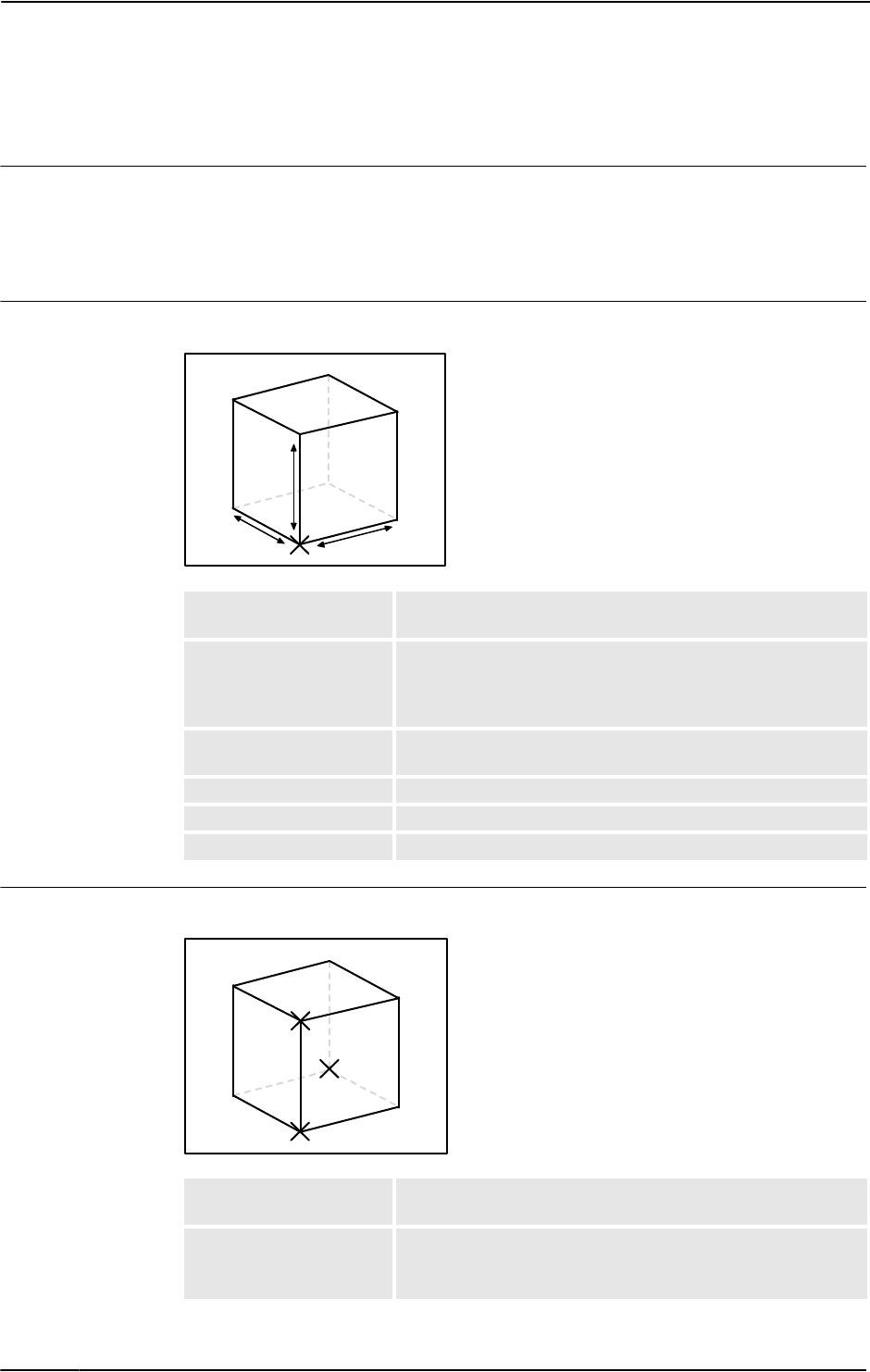
9 The Modeling Tab
9.5. Solid
3HAC032104-001 Revision: D268
© Copyright 2008-2010 ABB. All rights reserved.
9.5. Solid
Creating a solid
1. Click Solid and then click the type of solid you want to create to bring up a dialog box.
2. Enter requested values in in the dialog box and click Create. For detailed information
about the specific dialog box for the curve to create, see below:
The Create Box dialog box
xx0600002655
The Create Box from 3-Points dialog box
xx0600002662
Reference Select the Reference coordinate system to which all positions
or points will be related.
Corner Point (A) Click in one of these boxes, and then click the corner point in the
graphics window to transfer the values to the Corner Point
boxes, or type the position. The corner point will be the local
origin of the box.
Orientation If the object shall be rotated relative to the reference coordinate
system, specify the rotation.
Length (B) Specify the box dimension along its X axis.
Width (C) Specify the box dimension along its Y axis.
Height (D) Specify the box dimension along its Z axis.
A
B
C
D
Reference Select the Reference coordinate system to which all positions
or points will be related.
Corner Point (A) This point will be the local origin of the box.
Either type the position, or click in one of the boxes and then
select the point in the graphics window.
A
C
B
Continues on next page

9 The Modeling Tab
9.5. Solid
2693HAC032104-001 Revision: D
© Copyright 2008-2010 ABB. All rights reserved.
The Create Cone dialog box
xx0600002663
Point on diagonal of XY-
plane (B)
This point is the the corner, diagonal to the local origin. It sets
the X and Y directions of the local coordinate system, as well as
the dimension of the box along these axes.
Either type the position, or click in one of the boxes and then
select the point in the graphics window.
Indication Point Z-axis
(C)
This point is the corner above the local origin, It sets the Z
direction of the local coordinate system, as well as the
dimension of the box along the Z axis.
Either type the position, or click in one of the boxes and then
select the point in the graphics window.
Reference Select the Reference coordinate system to which all positions
or points will be related.
Base Center Point (A) Click in one of these boxes, and then click the center point in the
graphics window to transfer the values to the Base Center
Point boxes, or type the position. The center point will be the
local origin of the cone.
Orientation If the object shall be rotated relative to the reference coordinate
system, specify the rotation.
Radius (B) Specify the radius of the cone.
Diameter Specify the diameter of the cone.
Height (C) Specify the height of the cone.
A
B
C
Continued
Continues on next page

9 The Modeling Tab
9.5. Solid
3HAC032104-001 Revision: D270
© Copyright 2008-2010 ABB. All rights reserved.
The Create Cylinder dialog box
xx0600002664
The Create Pyramid dialog box
xx0600002667
Reference Select the Reference coordinate system to which all positions
or points will be related.
Base Center Point (A) Click in one of these boxes, and then click the center point in the
graphics window to transfer the values to the Base Center
Point boxes, or type the position. The center point will be the
local origin of the cylinder.
Orientation If the object shall be rotated relative to the reference coordinate
system, specify the rotation.
Radius (B) Specify the radius of the cylinder.
Diameter Specify the diameter of the cylinder.
Height (C) Specify the height of the cylinder.
A
C
B
Reference Select the Reference coordinate system to which all positions
or points will be related.
Base Center Point (A) Click in one of these boxes, and then click the center point in the
graphics window to transfer the values to the Base Center
Point boxes, or type the position. The center point will be the
local origin of the pyramid.
Orientation If the object shall be rotated relative to the reference coordinate
system, specify the rotation.
Center to Corner Point
(B)
Either type the position, or click in the box and then select the
point in the graphics window.
Height (C) Specify the height of the pyramid.
Number of Sides Specify the number of sides of the pyramid. The maximum
number of sides is 50.
A
B
C
Continued
Continues on next page

9 The Modeling Tab
9.5. Solid
2713HAC032104-001 Revision: D
© Copyright 2008-2010 ABB. All rights reserved.
The Create Sphere dialog box
xx0600002668
Reference Select the Reference coordinate system to which all positions
or points will be related.
Center Point (A) Click in one of these boxes, and then click the center point in the
graphics window to transfer the values to the Center Point
boxes, or type the position. The center point will be the local
origin of the sphere.
Radius (B) Specify the radius of the sphere.
Diameter Specify the diameter of the sphere.
B
A
B
Continued

9 The Modeling Tab
9.6. Surface
3HAC032104-001 Revision: D272
© Copyright 2008-2010 ABB. All rights reserved.
9.6. Surface
Creating a surface
1. Click Surface and then click the type of solid you want to create to bring up a dialog box.
2. Enter requested values in in the dialog box and click Create. For detailed information
about the specific dialog box for the curve to create, see below:
The Create Surface Circle dialog box
xx0600002669
The Create Rectangle dialog box
xx0600002671
Reference Select the Reference coordinate system, to which all positions
or points will be related.
Center Point (A) Click in one of these boxes, and then click the center point in the
graphics window to transfer the values to the Center Point
boxes, or type the position. The center point will be the local
origin of the circle.
Orientation If the object shall be rotated relative to the reference coordinate
system, specify the rotation.
Radius (B) Specify the radius of the circle.
Diameter Specify the diameter of the circle.
A
B
Reference Select the Reference coordinate system to which all positions
or points will be related.
Start Point (A) Click in one of these boxes, and then click the center point in the
graphics window to transfer the values to the Start Point boxes,
or type the position. The start point will be the local origin of the
rectangle.
Orientation If the object shall be rotated relative the reference coordinate
system, specify the rotation.
A
B
C
Continues on next page

9 The Modeling Tab
9.6. Surface
2733HAC032104-001 Revision: D
© Copyright 2008-2010 ABB. All rights reserved.
The Create Surface Polygon dialog box
xx0600002670
The Create Surface from Curve dialog box
Length (B) Specify the length of the rectangle.
Width (C) Specify the width of the rectangle
Reference Select the Reference coordinate system to which all positions
or points will be related.
Center Point Click in one of these boxes, and then click the center point in the
graphics window to transfer the values to the Center Point
boxes, or type the position. The center point will be the local
origin of the polygon.
First Vertex Point Either type the position, or click in one of the boxes and then
select the point in the graphics window.
Vertices Specify the number of the vertices here. The maximum number
of vertices is 50.
A
B
Select Curve from
graphics
Select a curve by clicking it in the graphics window.
Continued

9 The Modeling Tab
9.7. Curve
3HAC032104-001 Revision: D274
© Copyright 2008-2010 ABB. All rights reserved.
9.7. Curve
Creating a curve
1. Click Curve and then click the curve you want to create to bring up a dialog box.
2. Enter requested values in in the dialog box and click Create. For detailed information
about the specific dialog box for the curve to create, see below:
The Create Line dialog box
xx0500001513
The Create Circle dialog box
xx0500001512
Reference Select the Reference coordinate system to which all positions
or points will be related.
Start point (A) Click in one of these boxes, and then click the start point in the
graphics window to transfer the values to the Start Point boxes.
End Point (B) Click in one of these boxes, and then click the end point in the
graphics window to transfer the values to the End Point boxes.
Reference Select the Reference coordinate system to which all positions
or points will be related.
Center point (A) Click in one of these boxes, and then click the center point in the
graphics window to transfer the values to the Center Point
boxes.
Orientation Specify the orientation coordinates for the circle.
Radius (A-B) Specify the radius of the circle.
Diameter Alternatively, specify the diameter.
Continues on next page

9 The Modeling Tab
9.7. Curve
2753HAC032104-001 Revision: D
© Copyright 2008-2010 ABB. All rights reserved.
The Create Three Points Circle dialog box
xx0500001518
The Create Arc dialog box
xx0500001520
Reference Select the Reference coordinate system to which all positions
or points will be related.
First Point (A) Click in one of these boxes, and then click the first point in the
graphics window to transfer the values to the First Point boxes.
Second Point (B) Click in one of these boxes, and then click the second point in
the graphics window to transfer the values to the Second Point
boxes.
Third Point (C) Click in one of these boxes, and then click the third point in the
graphics window to transfer the values to the Third Point
boxes.
Reference Select the Reference coordinate system to which all positions
or points will be related.
Start Point (A) Click in one of these boxes, and then click the start point in the
graphics window to transfer the values to the Start Point boxes.
Mid Point (B) Click in one of these boxes, and then click the second point in
the graphics window to transfer the values to the Mid Point
boxes.
End Point (C) Click in one of these boxes, and then click the end point in the
graphics window to transfer the values to the End Point boxes.
Continued
Continues on next page

9 The Modeling Tab
9.7. Curve
3HAC032104-001 Revision: D276
© Copyright 2008-2010 ABB. All rights reserved.
The Create Elliptical Arc dialog box
xx0500001522
The Create Ellipse dialog box
xx0500001521
Reference Select the Reference coordinate system to which all positions
or points will be related.
Center Point (A) Click in one of these boxes, and then click the center point in the
graphics window to transfer the values to the Center Point
boxes.
Major Axis End Point (B) Click in one of these boxes, and then click the end point for the
major axis of the ellipse in the graphics window to transfer the
values to the Major Axis End Point boxes.
Minor Axis End Point (C) Click in one of these boxes, and then click the end point for the
minor axis of the ellipse in the graphics window to transfer the
values to the Minor Axis End Point boxes.
Start Angle (α) Specify the start angle for the arc, measured from the major
axis.
End Angle (β) Specify the end angle for the arc, measured from the major axis.
Reference Select the Reference coordinate system to which all positions
or points will be related.
Center Point (A) Click in one of the Center Point boxes, and then click the center
point in the graphics window to transfer the values to the Center
Point boxes.
Major Axis End Point (B) Click in one of these boxes, and then click the end point for the
major axis of the ellipse in the graphics window to transfer the
values to the Major Axis End Point boxes.
Minor Radius (C) Specify the length of the minor axis of the ellipse. The minor
radius will be created perpendicular to the major axis.
Continued
Continues on next page

9 The Modeling Tab
9.7. Curve
2773HAC032104-001 Revision: D
© Copyright 2008-2010 ABB. All rights reserved.
The Create Rectangle dialog box
xx0500001516
The Create Polygon dialog box
xx0500001514
Reference Select the Reference coordinate system to which all positions
or points will be related.
Start Point (A) Click in one of these boxes, and then click the start point in the
graphics window to transfer the values to the Start Point boxes.
The rectangle will be created in the positive coordinate
directions.
Orientation Specify the orientation coordinates for the rectangle.
Length (B) Specify the length of the rectangle along the x axis.
Width (C) Specify the width of the rectangle along the y axis.
Reference Select the Reference coordinate system to which all positions
or points will be related.
Center Point (A) Click in one of these boxes, and then click the center point in the
graphics window to transfer the values to the Center Point
boxes.
First Vertex Point (B) Click in one of these boxes, and then click the first vertex point
in the graphics window to transfer the values to the First Vertex
Point boxes. The distance between the center point and the first
vertex point will be used for all vertex points.
Vertices Specify the number of points to be used when creating the
polygon. The maximum number of vertices is 50.
Continued
Continues on next page
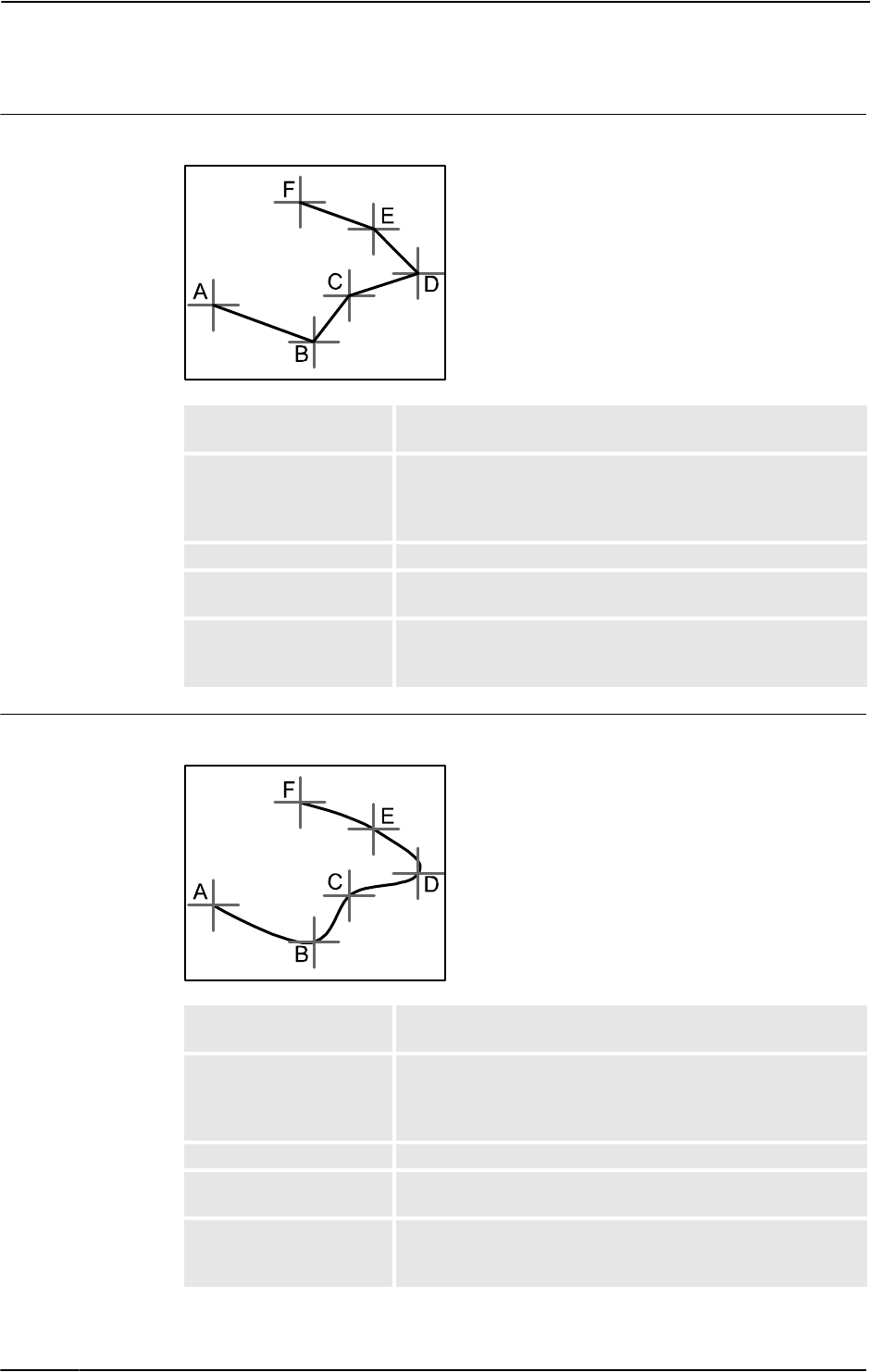
9 The Modeling Tab
9.7. Curve
3HAC032104-001 Revision: D278
© Copyright 2008-2010 ABB. All rights reserved.
The Create Polyline dialog box
xx0500001515
The Create Spline dialog box
xx0500001517
Reference Select the Reference coordinate system to which all positions
or points will be related.
Point Coordinates Specify each node of the polyline here, one at a time, by either
typing the values, or by clicking in one of these boxes, and then
selecting the point in the graphics window to transfer its coordi-
nates.
Add Click this button to add a point and its coordinates to the list.
Modify Click this button to modify an already defined point, after you
have selected it in the list and entered new values.
List The nodes of the polyline. To add more nodes, click Add New,
click the desired point in the graphics window, and then click
Add.
Reference Select the Reference coordinate system to which all positions
or points will be related.
Point Coordinates Specify each node of the spline here, one at a time, by either
typing the values, or by clicking in one of these boxes, and then
selecting the point in the graphics window to transfer its coordi-
nates.
Ad Click this button to add a point and its coordinates to the list.
Modify Click this button to modify an already defined point, after you
have selected it in the list and entered new values.
List This nodes of the spline. To add more nodes, click Add New,
click the desired point in the graphics window, and then click
Add.
Continued
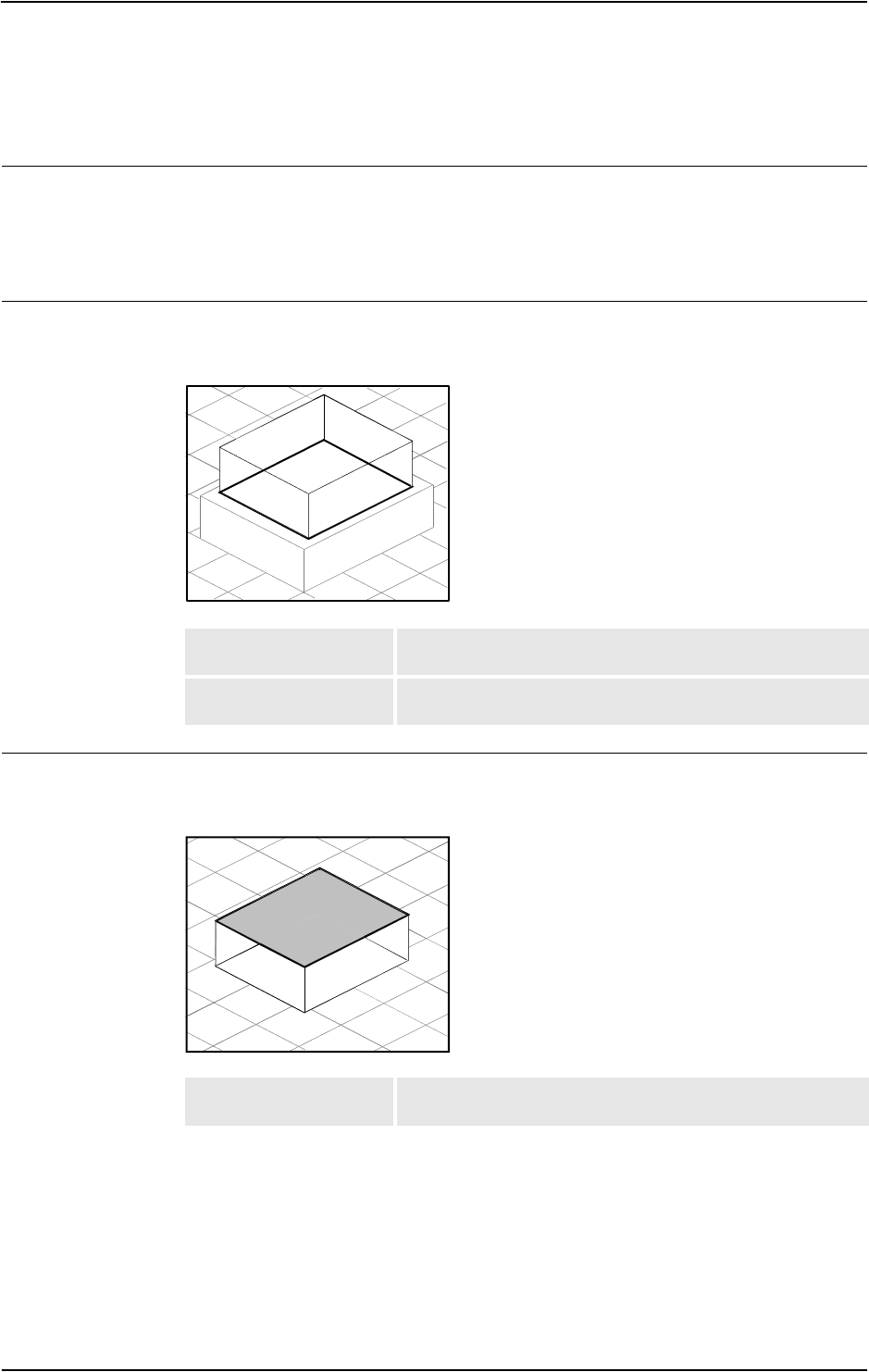
9 The Modeling Tab
9.8. Border
2793HAC032104-001 Revision: D
© Copyright 2008-2010 ABB. All rights reserved.
9.8. Border
Creating a curve
1. Click Border and then click the border you want to create to bring up a dialog box.
2. Enter requested values in in the dialog box and click Create. For detailed information
about the specific dialog box for the border to create, see below:
The Create Border Between Bodies dialog box
To use the create border between bodies command, the station must contain at least two
objects.
xx0500001524
The Create Border Around Surface dialog box
To use the create border around surface command, the station must contain at least one object
with a graphical representation.
xx0500001523
First Body Click in this box and then select the first body in the graphics
window.
Second Body Click in this box and then select the second body in the graphics
window.
Select Surface Click in this box and then select a surface in the graphics
window.
Continues on next page

9 The Modeling Tab
9.8. Border
3HAC032104-001 Revision: D280
© Copyright 2008-2010 ABB. All rights reserved.
The Create Border From Points dialog box
To use the create border from points command, the station must contain at least one object.
en0500001531
Selected Object Click in this box and then select an object in the graphics
window.
Point Coordinates Specify the points that define the border here, one at a time, by
either typing the values, or by clicking in one of these boxes, and
then selecting the point in the graphics window to transfer its
coordinates.
Add Click this button to add a point and its coordinates to the list.
Modify Click this button to modify an already defined point, after you
have selected it in the list and entered new values.
List The points that define the borders. To add more points, click
Add New, click the desired point in the graphics window, and
then click Add.
Continued

9 The Modeling Tab
9.9. Intersect
2813HAC032104-001 Revision: D
© Copyright 2008-2010 ABB. All rights reserved.
9.9. Intersect
The Intersect dialog box
xx0600002673
Keep Original Select this check box to keep the original bodies when creating
the new body.
Intersect... (A) Select the body from which you want to make an intersection (A)
by clicking it in the graphics window.
...and (B) Select the body with which you want to make an intersection (B)
by clicking it in the graphics window.
A new body will be created based on the common area between
the selected bodies A and B.
AB

9 The Modeling Tab
9.10. Subtract
3HAC032104-001 Revision: D282
© Copyright 2008-2010 ABB. All rights reserved.
9.10. Subtract
The Subtract dialog box
xx0600002674
Keep Original Select this check box to keep the original bodies when creating
the new body.
Subtract... (A) Select the body from which you want to subtract (A) by clicking
it in the graphics window.
...with (B) Select the body you want to subtract (B) by clicking it in the
graphics window.
A new body will be created based on the area of body A
subtracted with the common volume between body A and B.
AB

9 The Modeling Tab
9.11. Union
2833HAC032104-001 Revision: D
© Copyright 2008-2010 ABB. All rights reserved.
9.11. Union
The Union dialog box
xx0600002672
Keep Original Select this check box to keep the original bodies when creating
the new body.
Union... (A) Select the body that you want to unify (A) by clicking it in the
graphics window.
...and (B) Select the body that you want to unify (B) by clicking it in the
graphics window.
A new body will be created based on the areas of the two
selected bodies A and B.
AB

9 The Modeling Tab
9.12. Extrude Surface or Curve
3HAC032104-001 Revision: D284
© Copyright 2008-2010 ABB. All rights reserved.
9.12. Extrude Surface or Curve
Extruding a surface or curve
1. From the selection level toolbar, select Surface or Curve, as appropriate.
2. In the graphics window, select the surface or curve you wish to extrude. Click Extrude
Surface or Extrude Curve, as appropriate. The Extrude Surface or Curve dialog box
opens below the Modeling browser.
3. For extrusion along a vector, fill in the values.
For extrusion along a curve, select the Extrude Along Curve option. Click the Curve
box, and select the curve in the Graphics window.
4. If you wish the form to appear as a surface model, clear the Make Solid check box.
5. Click Create.
The Extrude Surface or Curve dialog box
Surface or Curve Denotes the surface or curve to be extruded.
To select the surface or curve, first click in the box, then select
the surface or curve in the graphics window.
Extrude Along Vector Enables extrusion along a specified vector.
From Point (mm) The start point of the vector.
To Point (mm) The end point of the vector.
Extrude Along Curve Enables extrusion along a specified curve.
Curve Denotes the curve used as a sweep path.
xx0600003076
To select the curve, first click the box, then the curve in the
graphics window.
Make Solid Select this check box to convert the extruded form into a solid.

9 The Modeling Tab
9.13. Line from Normal
2853HAC032104-001 Revision: D
© Copyright 2008-2010 ABB. All rights reserved.
9.13. Line from Normal
Creating a line from normal
1. Click Surface Selection.
2. Click Line to Normal to bring up a dialog box.
3. Click on a face to select it in the Select Face box.
4. In the Length box, specify a length for the line.
5. Optionally, select the Invert Normal check box to invert the direction of the line.
6. Click Create.
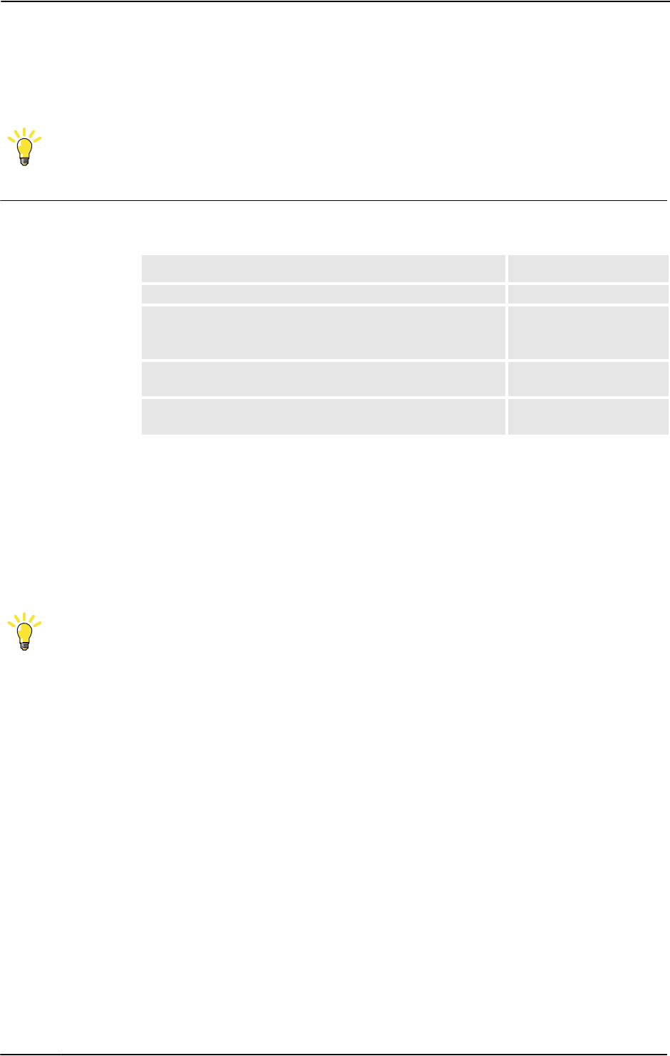
9 The Modeling Tab
9.14. The Measure Group
3HAC032104-001 Revision: D286
© Copyright 2008-2010 ABB. All rights reserved.
9.14. The Measure Group
TIP!
Make sure to select the appropriate snap mode and selection levels before making your
measurements.
Measuring distances or angles
1. Click the type of measurement you want to use:
The mouse pointer will turn into a ruler when you have activated any of the measurement
functions.
2. In the graphics window, select the points or objects to measure between. Information
about the measuring points is displayed in the Output window.
The results will be displayed in the Measurements tab in the Output window when all
points have been selected.
3. Optionally, repeat step 3 for making a new measurement of the same type.
TIP!
You can also activate and deactivate the measurement functions from the measurement
toolbar.
To measure the Select
distance between two points you select in the graphics window. Point to point
angle defined by three points you select in the graphics window.
The first point to select is the converging point, thereafter you
shall select one point on each line.
Angle
diameter, with the circle defined by three points you select from
the graphics window.
Diameter
closest distance between two objects you select in the graphics
window.
Minimum distance

9 The Modeling Tab
9.15. Create Mechanism
2873HAC032104-001 Revision: D
© Copyright 2008-2010 ABB. All rights reserved.
9.15. Create Mechanism
Create a new mechanism
1. Click Create Mechanism.
The Mechanism Modeler opens in create mode.
2. In the Mechanism Model Name box, enter a mechanism name.
3. From the Mechanism Type list, select a mechanism type.
4. In the tree structure, right-click Links, and then click Add Link to bring up the Create
Link dialog box.
A suggested name appears in the Link Name box.
5. In the Selected Part list, select a part (which will be highlighted in the graphics window)
and click the arrow button to add the part to the Parts list box.
The Selected Part list then automatically selects the next part, if any more are available.
Add these, as required.
6. Select a part in the Parts list box, enter any values in the Selected Parts group boxes, and
then click Apply to Part.
Repeat for each part, as required.
7. Click OK.
8. In the tree structure, right-click Joints, and then click Add Joint to bring up the Create
Joint dialog box.
A suggested name appears in the Joint Name box.
9. Complete the Create Joint dialog box, and then click OK.
10.In the tree structure, right-click Frame/Tool Data, and then click Add Frame/Tool to
bring up the Create Frame/Tool dialog box.
A suggested name appears in the Frame/Tool Data name box.
11. Complete the Create Frame/Tool dialog box, and then click OK.
The validity criteria for the Frame/Tool node are as follows:
12.In the tree structure, right-click Calibration, and then click Add Calibration to bring up
the Create Calibration dialog box.
13.
Complete the Create Calibration dialog box, and then click OK.
14.In the tree structure, right-click Dependency, and then click Add Dependency to bring
up the Create Dependency dialog box.
15.Complete the Create Dependency dialog box, and then click OK.
16.If all nodes are valid, compile the mechanism, see Compiling a mechanism on page 288.
Create Conveyor mechanism
1. Click Create Mechanism.
The Mechanism Modeler opens in create mode.
2. In the Mechanism Model Name dialog box, enter a mechanism name.
3. From the Mechanism Type list, select Conveyor.
4. From the Selected Part list, select Part.
Continues on next page

9 The Modeling Tab
9.15. Create Mechanism
3HAC032104-001 Revision: D288
© Copyright 2008-2010 ABB. All rights reserved.
5. In the Position of Calibration frame list, enter the base frame values relative to the local
origin of the selected graphic component.
6. In the Conveyor length box, enter the length of the conveyor.
The Compile Mechanism button is enabled.
7. In the Attachment Points box, set the Pitch and Count value.
8. Click Add to create new attachment points.
9. Click Compile Mechanism, to compile the mechanism. See Compiling a mechanism on
page 288.
10. In the Layout browser, right-click the conveyor mechanism and select Save As Library.
Close the station.
11. Build a new system. See Building a new system on page 148.
NOTE! On the Modify Options page of the System Builder, scroll down to the Motion
coordination part 3 group and select 606-1 Conveyor Tracking check box.
12. Create new station using this new system. See Robot System on page 192.
NOTE! After starting the system, when asked to select the library for the conveyor
mechanism browse and select the already saved library.
Compiling a mechanism
When compiling, a new mechanism, created in the create mode of the Mechanism Modeler,
is added to the station with the default name "Mechanism_" followed by an index number.
When compiling, an existing editable mechanism, modified in the modify mode of the
Mechanism Modeler, is saved without any poses, joint mapping ot transition times.
To compile a mechanism, follow these steps:
1. To compile a new or edited mechanism, click Compile Mechanism.
The mechanism is inserted into the active station. The link parts are cloned with new
names, but the corresponding links will update their part references. When the
Mechanism modeler is closed, these cloned parts will be removed.
2. The Mechanism Modeler now switches to modify mode. To complete the mechanism, see
below.
Completing or modifying a mechanism
To complete the modeling of a mechanism, follow these steps:
1. If the values in the Joint Mapping group are correct, click Set.
2. Configure the Poses grid. To add a pose, click Add and then complete the Create Pose
dialog box. Click Apply, followed by OK.
To add a pose, click Add and then complete the Create Pose dialog box. Click Apply,
followed by OK.
To edit a pose, select it in the grid, click Edit, and then complete the Modify Pose dialog
box. Click OK.
To remove a pose, select it in the grid and then click Remove.
3. Click Edit Transition Times to edit transition times.
4. Click Close.
Continued
Continues on next page

9 The Modeling Tab
9.15. Create Mechanism
2893HAC032104-001 Revision: D
© Copyright 2008-2010 ABB. All rights reserved.
The Create Mechanism dialog box
The Create Conveyor Mechanism dialog box
The Create/Modify Link dialog box
A link is a moving component of a mechanism. Selecting a link node will highlight it in the
graphics window.
Mechanism Model Name Specifies the model name of the mechanism.
Mechanism Type Specifies the mechanism type.
Tree structure The components of the mechanism in a tree structure. The tree
structure will not be visible unless the mechanism is editable.
Each node (link, joint, frame, calibration and dependency) can
be edited in its own dialog box, see below.
Compile Mechanism Click this button to compile the mechanism. This button will not
be visible unless the mechanism is editable and the mechanism
model name is valid.
Mechanism Model Name Specifies the model name of the conveyor mechanism.
Mechanism Type Specifies the diffrent mechanism types.
Selected Part Specifies the part to be selected for the conveyor.
Position of Calibration
frame
Specifies the baseframe value relative to the local origin of the
selected graphic component.
Conveyor Length Specifies the length of the conveyor.
Attachment Points Specifies the conveyor position to attach the workpieces.
Compile Mechanism Click this button to compile the mechanism. This button will not
be visible unless the mechanism is editable and the mechanism
model name is valid.
Link Name Specifies the name of the link.
Selected Part Specifies the parts to add to the Part list box.
Set as BaseLink The BaseLink is where the kinematical chain begins. This must
be the parent of the first joint. A mechanism may have only one
BaseLink.
xx0600003086
Adds a selected part to the Part list box.
Remove Part Click this button to remove a selected part from the Part list box.
Selected Part This group manipulates the transform of the selected part.
Part Position Specify the position of the part.
Part Orientation Specify the orientation of the part.
Apply to Part Click this button to apply the settings to the part.
Continued
Continues on next page

9 The Modeling Tab
9.15. Create Mechanism
3HAC032104-001 Revision: D290
© Copyright 2008-2010 ABB. All rights reserved.
The Create/Modify Joint dialog box
A joint is the axis where two links move in relation to each other, rotationally or prismatically.
Selecting a joint node will display a yellow-green line in the graphics window.
Joint Name Specifies the name of the joint.
Joint Type. Specifies the joint type. The default option is Rotational.
Changing the Joint Type clears the Joint Limits below.
Parent Link Specifies the parent link, usually the first joint of the mechanism.
Child Link Specifies the child link. To be valid, the parent and child links
may not be identical to each other, and the pair must be unique.
Active Select this check box to make the joint active. An active joint is
one that a user can move, while an inactive joint is a slave to an
active joint.
Joint Axis This group specifies the axis around or along which the child
moves.
First Position Specify the start point of the axis vector.
Second Position Specify the end point of the axis vector.
Jog Axis Demonstrates how the child link moves along its axis.
Limit Type Specifies the limits in each direction to which a joint may move.
The options are Constant, Variable and No.
Joint Limits This group is visible in Constant or Variable mode.
Min Limit Specifies the minimum joint limit.
Max Limit Specifies the maximum joint limit.
Joint Limits This group is visible in Constant or Variable mode.
Variable Limits In Variable mode, variable limit points may be added as an
advanced way of delimiting the area of movement.
xx0600003106
xx0600003086
Adds a selected point to the Point list box.
Remove Click this button to remove a selected point from the Point list
box.
Continued
Continues on next page

9 The Modeling Tab
9.15. Create Mechanism
2913HAC032104-001 Revision: D
© Copyright 2008-2010 ABB. All rights reserved.
The Modify Frame/Tool Data dialog box
A frame/tool data node determines the link and location of a frame.
The Create Calibration dialog box
A calibration contains transforms for calibrating the joints. Two calibrations cannot share the
same joint.
The Create Dependency dialog box
A dependency is a relationship between two joints, by either a factor or a complex formula.
The Modify Mechanism dialog box
The Modify Mechanism dialog box contains the objects found in the Create mechanism
dialog box, as well as the following:
Frame/Tool Data name Specifies the name of the frame or tool data.
Belongs to Link Specifies the link to which the frame or tool belongs.
Position Specify the position of the transform.
Orientation Specify the orientation of the transform.
Select values from target/
Frame
Select this box to select the values from a target or frame, which
is selected in the box beneath the check box.
Tool Data This group is visible if the mechanism is a tool.
Mass Specifies the mass of the tool.
Center of Gravity Specify the center of gravity of the tool.
Moment of Inertia lx, ly, lz Specify the moment of inertia of the tool.
Calibration belongs to
Joint
Specifies the joint to be calibrated.
Position Specify the position of the transform.
Orientation Specify the orientation of the transform.
Joint Specifies the joint whose motion will be controlled by other
joints.
Use LeadJoint and factor Select this option to specify a lead joint and factor.
LeadJoint Specifies the lead joint.
Factor This list holds a double which denotes the extent to which the
lead joint will control the main joint.
Use Formula Select this option to enter a formula in the box.
Joint Mapping These boxes handle the joint mapping of the mechanism. When
editing, the mechanism must be disconnected from its library.
The values must be integers from 1 – 6 in ascending order.
Set Click this button to set the joint mapping.
Poses Displays the poses and their joint values.
Selecting a pose will move the mechanism to it in the graphics
window.
Add Click this button to bring up the Create Pose dialog box for
adding a pose.
Continued
Continues on next page

9 The Modeling Tab
9.15. Create Mechanism
3HAC032104-001 Revision: D292
© Copyright 2008-2010 ABB. All rights reserved.
The Create/Modify Pose dialog box
The Set Transition Times dialog box
The Set Transition Times dialog box is designed like a distance table in a road atlas. The
default values are zero.
Edit Click this button to bring up the Modify Pose dialog box for
editing a selected pose.
A SyncPose cannot be edited unless the mechanism is discon-
nected from its library.
Remove Click this button to remove the selected pose.
A single SyncPose cannot be removed.
Set Transition Times Click this button to edit the transition times.
Pose Name Specifies the name of the pose. If the pose is a SyncPose, this
box is not editable.
The names "HomePosition" and "SyncPosition" are disallowed.
Home Pose Select this box to specify the home pose of the mechanism. If
selected, the non-editable pose name will be "HomePose".
Launch Joint Jog Tool Click this button to bring up the joint jog tool.
Use Current Click this button to set the current joint values in the Joint
Values group.
Reset Values Click this button to reset the joint values in the Joint Values
group to what they were when the dialog box was opened.
Joint Values Specify the joint values of the pose.
From Pose Specifies the start of the transition for the named pose.
To Pose Specifies the end of the transition for the named pose.
Continued

9 The Modeling Tab
9.16. Create Tool
2933HAC032104-001 Revision: D
© Copyright 2008-2010 ABB. All rights reserved.
9.16. Create Tool
Creating a tool
You can create a robot hold tool by using the Create Tool Wizard. The wizard allows you to
easily create a tool from an existing part or by using a dummy part to represent a tool. To
create a tool complete with tooldata, follow these steps:
1. Click Create Tool.
2. In the Tool Name box, enter a tool name and choose one of the following options:
3. Continue entering the Mass of the tool, the Center of Gravity and the Moment of Inertia
Ix, Iy, Iz, if these values are known. If you do not know the correct values, the tool can
still be used for programming motions, but this data must be corrected before running the
program on real robots or measuting cycle times.
Tip! If the tool is built from materials with a similar density, you can find the center of
gravity by clicking the tool model using the Center of gravity snap mode.
4. Click Next to go the next page of the wizard.
5. In the TCP Name box, enter a name for the Tool Center Point (TCP). The default name
is the same as the name of the tool. If creating several TCPs for one tool, each TCP must
have a unique name.
6. Enter the position of the TCP relative to the world coordinate system, which represents
the tool mounting point, by any of the methods below:
7. Click the arrow right button to transfer the values to the TCP(s): box.
If the tool shall have several TCPs, repeat steps 5 to 7 for each TCP.
8. Click Done. The tool will be created and appear in the Objects browser and in the
graphics window.
Option Action
Use Existing Select one of the existing parts from the list. The selected part
will represent the tool graphics.
The selected part must be a single part. Parts with attache-
ments cannot be selected.
Use Dummy A cone will be created to represent the tool.
Method Description
Read values from existing
target or frame
Click in the Values from Target/Frame box, then select the
frame either in the graphics window or the Paths&Targets
browser.
Enter position and
orientation manually.
In the Position and Orientation boxes, type the values.
NOTE: If Use Dummy Part is selected, the position value can
not be 0,0,0. At least one coordinate has to be > 0 in order for a
cone to be created.
Continues on next page

9 The Modeling Tab
9.16. Create Tool
3HAC032104-001 Revision: D294
© Copyright 2008-2010 ABB. All rights reserved.
Creating tooldata for an existing geometry
To create tooldata for an existing geometry, follow these steps:
1. Make sure the robot in which to create the tooldata is selected.
2. Click Create Tool and select Use Existing and the imported tool from the list.
3. Enter the requested data in the boxes in the Create Tool Wizard.
4. Attach the tool by dragging it to the robot.
What to do next
To make the tool ready to use, do one of the following:
• To make the robot hold the tool, attach the tool to the robot.
• In the graphics window, check the position and orientation of the TCP. If it is incorrect,
modify the values in the tool frame part of the tooldata.
• To simplify future usage of the created tool, save it as a library. On the File menu, click
Save As Library. Browse to the folder where you want to store the tool component,
enter a name for the tool component and click Save.
Continued

10 The Simulation Tab
10.1. Overview
2953HAC032104-001 Revision: D
© Copyright 2008-2010 ABB. All rights reserved.
10 The Simulation Tab
10.1. Overview
The Simulation tab
The Simulation tab contains the controls for setting up, configuring, controlling, monitoring
and recording simulations.

10 The Simulation Tab
10.2. Create Collision Set
3HAC032104-001 Revision: D296
© Copyright 2008-2010 ABB. All rights reserved.
10.2. Create Collision Set
Overview
A collision set contains two groups, Objects A and Objects B, in which you place the objects
to detect any collisions between them. When any object in Objects A collides with any object
in Objects B, the collision is displayed in the graphical view and logged in the output window.
You can have several collision sets in the station, but each collision set can only contain two
groups.
Creating a collision set
1. Click Create Collision Set to create a collision set in the Layout browser.
2. Expand the collision set and then drag one of the objects to the ObjectsA node to check
for collisions.
If you have several objects you want to check for collisions with objects in the ObjectsB
node, for example, the tool and the robot, drag all of them to the ObjectsA node.
3. Drag the objects to the ObjectsB node to check for collisions.
If you have several objects you want to check for collisions with objects in the ObjectsA
node, for example, the work piece and the fixture, drag all of them to he ObjectsB node.
10 The Simulation Tab
10.3. Simulation Setup
2973HAC032104-001 Revision: D
© Copyright 2008-2010 ABB. All rights reserved.
10.3. Simulation Setup
Prerequisites
To set up a simulation, the following conditions must be met:
• At least one path must have been created in the station.
• The paths to be simulated must have been synchronized to the virtual controller.
Setting up a simulation
1. Click Simulation Setup to bring up a dialog box.
2. In the Select Active Tasks box, select the tasks to be active in the simulation.
3. If a single controller has been selected, select either the Continuous or Single Cycle
option.
4. From the Available Procedures list, transfer the procedures to be active in the simulation
to the Main Sequence lists by selecting them and clicking the left arrow button between
the lists. (This creates a procedure call in the main procedure).
5. To start the simulation from another procedure than the actual Main procedure (that is, to
set a temporary Main procedure instead of overwriting the current one), click Select entry
point and then specify the procedure to use as Main.
6. Click Apply to set the simulation. If you click OK, the simulation will be set and the
dialog box will be closed.
NOTE!
If the simulation uses events or involves several different controllers, the virtual time mode
Time Slice shall be used to make sure that the timing between the controllers is simulated
correctly. For more information about virtual time modes, see Simulation Overview on page
125.
The Setup Simulation dialog box
Select Active Tasks Select the tasks to be active in the simulation.
The Run Mode options Select the run mode when a single controller is selected. The
options are Continuous and Single Cycle.
Main Sequence Displays the procedures that will be run when you play the
simulation.
<- Click the arrow left button to transfer the selected procedure to
the Main Sequence box.
X Click this button to remove the selected procedures or
sequences from the Main sequence box.
arrow up Click the arrow up button to move the sequence up in the list in
the Main Sequence box or in the Available Procedures box.
arrow down Click the arrow down button to move the sequence down in the
list in the Main Sequence box or in the Available Procedures
box.
Available Procedures Displays all procedures available in the controller.
Select entry point Click this button to set up several simulations at the same time.
In the dialog box, enter a new name for the main procedure, and
select the procedures to be included in the new simulation. Click
OK.

10 The Simulation Tab
10.4. Event Manager
3HAC032104-001 Revision: D298
© Copyright 2008-2010 ABB. All rights reserved.
10.4. Event Manager
Creating an event
1. Click Event Manager.
2. Click Add to open the New Event Wizard.
3. Complete the New Event wizard to create the event.
Event manager main parts
xx0600003098
Part Description
1 The Task pane.
Here you create new events, or copy or delete existing events selected in the
Event grid.
2 The Event grid.
Displays all events in the station. Here you select events to edit, copy or
delete.
3 The Trigger editor.
Here you edit the properties of the events trigger. The upper part of the trigger
editor is the same for all triggers, and the lower part adapts to the selected
trigger type.
4 The Action editor.
Here you edit the properties of the events action. The upper part of the action
editor is the same for all actions, and the lower part adapts to the selected
action type.
Continues on next page

10 The Simulation Tab
10.4. Event Manager
2993HAC032104-001 Revision: D
© Copyright 2008-2010 ABB. All rights reserved.
The task pane parts
The event grid columns
In the event grid, each row is a an event and the columns in the grid display their properties.:
Part Description
Add Starts the Create New Event Wizard.
Delete Deletes the event selected in the Event grid.
Copy Copies the event selected in the Event grid.
Refresh Refreshes the Event manager.
Column Description
Activation Displays whether the event is active or not.
On = The action is always carried out when the trigger event
occurs.
Off = The action is not carried out when the trigger event occurs.
Simulation = The action is only carried out if the trigger event
occurs when running a simulation.
Trigger Type Displays the type of condition that triggers the action.
I/O signals changed = Changes a digital I/O signal.
I/O Connection = Simulates the behavior of a Programmable
Logic Controller (PLC).
Collision = Starts or ends a collision or near-miss between
objects in a collision set.
Simulation time = Sets the activation time.
Note: The Simulation time button is enabled once the activation
is set to Simulation.
The trigger type cannot be changed in the trigger editor. If you
want another trigger type than the current one, create a
completely new event.
Trigger System When the trigger type is I/O Signal Trigger, this column displays
to which system the signal used as trigger belongs.
A dash (-) signifies a virtual signal.
Trigger Name The name of the signal or collision set used as trigger.
Trigger Parameter Displays the condition of the event under which triggering
occurs.
0 = The I/O signal used as trigger switches to false.
1 = The I/O signal used as trigger switches to true.
Started = A collision starts within the collision set used as
trigger.
Ended = A collision ends within the collision set used as trigger.
Near miss started = A near-miss starts within the collision set
used as trigger.
Near miss ended = A near-miss ends within the collision set
used as trigger.
Continued
Continues on next page

10 The Simulation Tab
10.4. Event Manager
3HAC032104-001 Revision: D300
© Copyright 2008-2010 ABB. All rights reserved.
Action Type Displays the action type that occurs in conjunction with the
trigger
I/O Signal Action = Changes the value of a digital input or
output signal.
Attach Object = Attaches an object to another.
Detach Object = Detaches an object from another.
Turn On/Off Simulation Monitor = Toggles the simulation
monitor of a specific mechanism.
Turn On/Off Timer = Toggles the process timer.
Move Mechanism to Pose = Moves the selected mechanism
to a predefined pose and thereafter sends a station signal.
Activates or deactivates the process timer.
Move Graphical Object = Moves a graphical object to a new
position and orientation.
Show/Hide Graphical Object = Shows or hides the graphical
object.
Do Nothing = No action occurs.
Multiple = The event triggers multiple actions, either all at once
or one at a time, each time the trigger is activated. Each action
can be viewed in the action editor.
Action System When the action type is Change I/O, this column displays the
system to which the signal to change belongs.
A dash (-) signifies a virtual signal.
Action Name Displays the name of the signal to change, when the action type
is Change I/O.
Action Parameter Displays the condition after the action has occurred.
0 = The I/O signal will be set to false.
1 = The I/O signal will be set to true.
On = Turns the process timer on.
Off = Turns the process timer off.
Object1 -> Object2 = Displays the object to which another will
be attached when the action type is Attach object.
Object1 <- Object2 = Displays the object from which another
will be detached when the action type is Detach object.
Ended = A collision ends within the collision set used as trigger.
Near miss started = A near-miss starts within the collision set
used as trigger.
Near miss ended = A near-miss ends within the collision set
used as trigger.
Multiple = Signifies multiple actions.
Time Displays the time when the event trigger was executed.
Column Description
Continued
Continues on next page

10 The Simulation Tab
10.4. Event Manager
3013HAC032104-001 Revision: D
© Copyright 2008-2010 ABB. All rights reserved.
The trigger editor parts
In the trigger editor you set the properties of the trigger. The upper part of the editor is
common for all types of triggers, and the lower part adapts to the trigger type at hand.
Parts common to triggers
Parts specific to I/O signal triggers
Parts specific to I/O connection triggers
Parts specific to Collision triggers
Part Description
Activation Sets whether the event is active or not.
On = The action is always carried out when the trigger event
occurs.
Off = The action is not carried out when the trigger event occurs.
Simulation = The action is only carried out if the trigger event
occurs when running a simulation.
Comment Text box for comments and notes about the event.
Part Description
Active Controller Select the system to which the I/O to use as a trigger belongs.
Signals Displays all signals that can be used as triggers.
Trigger Condition For digital signals, sets whether the event shall trigger when the
signals are set as true or false.
For analog signals, which are only available for station signals,
the event shall trigger under any of the following conditions:
Greater than, Greater/Equal, Less than, Less/Equal, Equal
to, Not equal to.
Part Description
Add Opens a dialog box for adding an activator signal to the
Activator Signals pane.
Remove Removes a selected activator signal.
Add > Opens a dialog box for adding an operator symbol to the
Connections pane.
Remove Removes a selected operator symbol.
Delay (s) Specifies the delay in seconds.
Part Description
Collision Type Set the kind of collision to use as trigger.
Started = Triggers when a collision starts.
Ended = Triggers when a collision ends.
Near miss started =Triggers when a near-miss starts.
Near miss ended = Triggers when a near-miss ends.
Collision set Select the collision set to use as trigger.
Continued
Continues on next page

10 The Simulation Tab
10.4. Event Manager
3HAC032104-001 Revision: D302
© Copyright 2008-2010 ABB. All rights reserved.
The action editor parts
In the action editor you set the properties of the actions for the event. The upper part of the
editor is common to all types of actions, and the lower part adjusts to the selected action.
Parts common to all actions
Parts specific to I/O Actions
Parts specific to Attach actions
Part Description
Add Action Adds a new action that occurs when the triggering condition
fulfills. You can add several different actions that either are
performed at once or one at a time each time the event triggers.
The following types of actions are available:
Change I/O = Changes the value of a digital input or output
signal.
Attach object = Attaches an object to another.
Detach object = Detaches and object from another.
Turn On/Off Timer = Activates or deactivates the process timer.
Do Nothing = No action occurs (might be useful for manipulat-
ing sequences of actions).
Remove Action Removes the action selected in the Added Actions list.
Cyclic When selected, the actions are performed one at a time each
time the trigger occurs. When all actions in the list have been
performed, the event will restart with the first action in the list.
When cleared, all actions are performed at once every time the
trigger occurs.
Added Actions Lists all actions of the event, in the order they will be executed.
Arrow Rearranges the order in which the actions are executed.
Part Description
Active Controller Displays all systems of the station. Select the system to which
the I/O to change belongs.
Signals Displays all signals that can be set.
Action Sets whether the event shall set the signals to true or false.
If the action is connected to an I/O Connection, this group will
not be available.
Part Description
Attach object Select an object in the station to attach.
Attach to Select the object in the station to attach to.
Update position / Keep
position
Update position = Moves the local origin of the attached object
to the attachment point of the other object when making the
attachment. For mechanisms, the attachment point is the TCP
or the flange; for other objects, it is the local origin.
Keep position = Keeps the current position of the object to
attach when making the attachment.
Flange index If the mechanism you attach the object to has several flanges
(attachments points), select the one to use.
Offset Position Optionally, specify an offset between the objects when making
the attachment
Continued
Continues on next page

10 The Simulation Tab
10.4. Event Manager
3033HAC032104-001 Revision: D
© Copyright 2008-2010 ABB. All rights reserved.
Parts specific to Detach actions
Parts specific to Turn On/Off Simulation Monitor actions
Parts specific to Turn On/Off Timer actions
Parts specific to Move Mechanism to Pose actions
Parts specific to Move Graphical Object actions
Parts specific to Show/Hide Graphical Object actions
Parts specific for a Call VSTA Macro action
Offset Orientation Optionally, specify an offset between the objects when making
the attachment
Part Description
Part Description
Detach object Select an object in the station to detach.
Detach from Select the object in the station to detach from.
Part Description
Mechanism Selects the mechanism.
Turn Simulation Monitor
On/Off
Sets whether the action shall start or stop the simulation monitor
function.
Part Description
Turn On/Off Timer Sets whether the action shall start or stop the process timer.
Part Description
Mechanism Selects the mechanism.
Pose Selects between SyncPose and HomePose.
Station signal to set
when Pose reached
Lists the station signals that are sent after the mechanism
reaches its pose.
Add Digital Click this button to add a digital signal to the grid.
Remove Click this button to remove a digital signal from the grid.
Part Description
Graphical Object to Move Select a graphical object in the station to move.
New Position Sets the new position of the object.
New Orientation Sets the new orientation of the object.
Part Description
Graphical Object Select a graphical object in the station.
Show/Hide Sets whether the object is shown or hidden.
Part Description
Available Macros Displays all available macros in the station.
Continued

10 The Simulation Tab
10.5. Station Logic
3HAC032104-001 Revision: D304
© Copyright 2008-2010 ABB. All rights reserved.
10.5. Station Logic
Introduction to Station Logic
The Station Logic has some of the characteristics of a Smart Component. It can be used to
work with these characteristics on the station level.
The Station Logic editor consists of the following tabs similar to that of a Smart Component
editor:
• Compose
• Properties and Bindings
• Signals and Connections
• View
For more information on the characteristics of a Smart Component editor, see Smart
Component on page 236.
Opening Station Logic
You can launch Station Logic in any of the following two ways:
• In the Simulation tab, select Station Logic.
• In the Layout browser, right-click the station and select Station Logic.
Differences between Station Logic and Smart Component
The following table lists some of the differences while working with Station Logic and a
Smart Component:
Smart Component Station Logic
The Editor window consists of a text box
displaying the description of the component
that is used for modifying the text.
The Editor window do not have the
description text box wherein the description
can be modified.
The Compose tab has the following options:
• Child components
• Saved States
• Assets
The Compose tab has the following options:
• Child components
• Saved States
The Properties and Bindings tab has the
following options:
• Dynamic Properties
• Property Bindings
The Properties and Bindings tab has the
following options:
• Property Bindings
In the Signals and Connections tab, when
working with Add or Edit I/O Connections,
you do not have the option of selecting the
VCs in the station from the the Source
Object and Target Object list.
You can create connections to and from I/O
signals in a VC.
In the Signals and Connections tab, when
working with Add or Edit I/O Connections,
you have the option of selecting the VCs in
the station from the the Source Object and
Target Object list.

10 The Simulation Tab
10.6. Activate Mechanical Units
3053HAC032104-001 Revision: D
© Copyright 2008-2010 ABB. All rights reserved.
10.6. Activate Mechanical Units
To activate or deactivate mechanical units manually
1. Click Activate Mechanical Units to bring up a dialog box.
2. In the Activate Mechanical Units dialog box, select the check boxes for the mechanical
units to set as active. When activating a mechanical unit that shares a common drive unit,
the other mechanical unit sharing that drive unit will be deactivated automatically.

10 The Simulation Tab
10.7. Simulation Control
3HAC032104-001 Revision: D306
© Copyright 2008-2010 ABB. All rights reserved.
10.7. Simulation Control
Running a simulation
1. Optionally, click Enable Process Timer.
2. In the Simulation Control group, click the Play button.
The output window will now display messages from the virtual controller.
3. To pause the simulation, click the Pause button.
4. To stop the simulation, click the Stop button.
5. To reset the simulation to its initial state, click the Reset button.

10 The Simulation Tab
10.8. I/O Simulator
3073HAC032104-001 Revision: D
© Copyright 2008-2010 ABB. All rights reserved.
10.8. I/O Simulator
Setting I/O signals using the I/O Simulator
1. Click I/O Simulator. This opens the I/O simulator.
2. If the station contains several systems, select the appropriate one in the Select System list.
3. In the Filter list and I/O Range list, make selections that display the signals to set.
Depending on the filter used, you might also set a filter specification.
4. To change the value of a digital I/O signal, click it.
To change the value of an analog signal, type the new value in the value box.
The I/O Simulator window
With RobotStudio’s I/O simulator you view and manually set existing signals, groups and
cross-connections during program execution, thus making it possible to simulate or
manipulate the signals.
The I/O simulator displays the signals for one system at a time in groups of 16 signals. For
handling large sets of signals, you can filter which signals to display and also create custom
lists with favorite signals for quick access.
xx0500002555
Part Description
1. Select System. Select the system whose signals you want to view.
2. Filter type. Select the type of filter to use.
3. Filter Specification. Select the filter for limiting the signal display. For
example, if Board is set as filter type, then you select the board whose signals
you want to view.
Continues on next page

10 The Simulation Tab
10.8. I/O Simulator
3HAC032104-001 Revision: D308
© Copyright 2008-2010 ABB. All rights reserved.
Types of signal filters
Signal icons
4. Inputs. Displays all input signals that pass the applied filter.
If more than 16 signals pass, only 16 signals at a time are displayed. Then use
the I/O range list to select the signals to view.
5. Outputs Displays all output signals that pass the applied filter. If more than 16
signals pass, only 16 signals at a time are displayed. Then use the I/O range
list to select the signals to view.
6. Edit Lists. Click this button to create or edit lists of favorite signals.
7. I/O Range. When more than 16 signals pass the filter, use this list to select the
range of signals to display.
Part Description
Filter Description
Board Displays all signals on a specific board. To select a board, use
the Filter Specification list.
Group Displays all signals that belong to a specific group. To select a
group, use the Filter Specification list.
User List Displays all signals in a favorite list. To select a list, use the
Filter Specification list.
Digital Inputs Displays all digital input signals of the system.
Digital Outputs Displays all digital output signals of the system.
Analog Inputs Displays all analog input signals of the system.
Analog Outputs Displays all analog output signals of the system.
xx0500002558
Digital signal with value 1.
xx0500002558
Digital signal with value 0.
xx0500002558
The cross in the upper right corner indicates that the signals are
a cross-connection.
xx0500002558
The -1 in the upper right corner indicates that the signal is
inverted.
xx0500002562
Value box for groups or analog signals.
Continued

10 The Simulation Tab
10.9. Monitor
3093HAC032104-001 Revision: D
© Copyright 2008-2010 ABB. All rights reserved.
10.9. Monitor
The TCP Trace tab
The Alerts tab
Enable TCP Trace Select this check box to activate tracing of the TCP path for the
selected robot.
Trace length Specify the maximum length of the trace in millimeters.
Trace Color Displays the color of the trace when no alerts are activated. To
change the color of the trace, click the colored box.
Alert color Displays the color of the trace when any of the alerts defined on
the Alerts tab exceeds a threshold value. To change the color
of the trace, click the colored box.
Clear Trace Click this button to remove the current trace from the graphics
window.
Enable Simulation Alerts Select this check box to activate simulation alerts for the
selected robot.
Log Alerts to Output
Window
Select this check box to see a warning message when a
threshold value is exceeded. If TCP trace is not enabled, this is
the only display of the alert.
TCP Speed (m/s) Specify the threshold value for TCP speed alerts.
TCP Acceleration (m/s2) Specify the threshold value for TCP acceleration alerts.
Wrist Singularity (deg) Specify how close joint five can be to zero rotation before
alerting.
Joint Limits (deg) Specify how close each joint can be to its limits before alerting.

10 The Simulation Tab
10.10. Record Movie
3HAC032104-001 Revision: D310
© Copyright 2008-2010 ABB. All rights reserved.
10.10. Record Movie
Prerequisites
For optimal results, first configure the options, see Options:General:Screen Recorder on
page 183.
Recording the screen
1. In the Record Movie group, click Record application to capture the entire application
window, or Record graphics to capture just the graphics window.
2. When you are done, click Stop Recording. A dialog box appears in which you may
choose to save the recording or discard it.
3. Click View Recording to playback the latest capture.
Recording the simulation
1. In the Record Movie group, click Record Simulation to record the next simulation to a
video clip.
2. When you are done, click Stop Recording.
The simulation is saved in a default location which is displayed in the output window.
3. Click View Recording to playback the recording.
The recording of simulation starts when you click Play in the Simulation tab.
NOTE!
Record Simulation gives better output quality than Record application or Record
graphics.

10 The Simulation Tab
10.11.1. Conveyor Tracking
3113HAC032104-001 Revision: D
© Copyright 2008-2010 ABB. All rights reserved.
10.11 Conveyor Tracking Mechanism
10.11.1. Conveyor Tracking
Overview
Conveyor tracking is the function where the robot follows a workobject mounted on a moving
conveyor.
This section describes how to create a conveyor, add and remove objects to and from the
conveyor, create targets during tracking, and simulate conveyor.
For more information, see the Application manual - Conveyor tracking.
Conveyor tracking mechanism
This procedure describes the workflow for making a conveyor tracking system work in
RobotStudio.
1. Create a conveyor mechanism. See Create Conveyor mechanism on page 287.
2. Setup the conveyor. See Setting up a conveyor on page 194and Encoder Unit on page 372.
NOTE! To setup a conveyor tracking station with two robots working on the
sameconveyor. See
3. Jog the conveyor as well as the robot and teach some targets. See Mechanism Joint Jog
on page 394.
4. Simulate the conveyor. See Conveyor Simulation on page 312.
5. Remove objects from conveyor. See Removing objects from conveyor on page 194.

10 The Simulation Tab
10.11.2. Conveyor Simulation
3HAC032104-001 Revision: D312
© Copyright 2008-2010 ABB. All rights reserved.
10.11.2. Conveyor Simulation
Running a conveyor simulation
1. Create Action Instructions. See Action Instruction on page 221.
NOTE! Create the following five action instructions along with Move instructions:
ConfL\Off,ActUnit CNV1,WaitWObj Workobject_1, DropWObjWorkobject_1
and DeactUnit CNV1
.
The following program is an example showing how the sequence of instructions appears:
en080000451
NOTE! If an error occurs while executing the program, the controller reaches Guard state.
In this state, RobotStudio cannot execute the program during the next simulation. To
recover from this state, open the Control Panel and switch to Manual Mod and then to
Auto Mode.
For more information, see Application manual - Conveyor Tracking.
2. Synchronize to VC. See Synchronize to VC on page 364.
3. Set up the Simulation. See Simulation Setup on page 297.
4. Click Simulation.
The Conveyor Simulation dialog appears.
5. In the Conveyor Speed box, set the speed during simulation.
NOTE! To move the conveyor in the backward direction, select the Reverse check box.
6. Click Apply.
7. Click Play to run the simulation.
NOTE! The conveyor speed and direction can be changed while running the simulation.
NOTE!
To jump the conveyor back to the start position, click Reset. This button remains enabled as
long as the station has at least one conveyor.

11 The Online and Offline Tabs
11.1. Overview
3133HAC032104-001 Revision: D
© Copyright 2008-2010 ABB. All rights reserved.
11 The Online and Offline Tabs
11.1. Overview
The Online and Offline tabs
The Online tab contains the controls for managing the real controller whereas the Offline tab
contains the controls for synchronization, configuration and tasks assigned to the virtual
controller.
The Online and Offline tabs can be broadly classified into the following three categories:
• Common features in Online and Offline tabs
• Online specific features
• Offline specific features
For more information on working with the Online tab, see Working online on page 139.

11 The Online and Offline Tabs
11.2.1. Events
3HAC032104-001 Revision: D314
© Copyright 2008-2010 ABB. All rights reserved.
11.2 Common features in Online and Offline tabs
11.2.1. Events
The Event Log tab
en0400000842
Parts
1. Category
This list contains the following different event categories.
NOTE! The default category Common includes all categories.
• Common
• Operational
• System
• Hardware
• Program
• Motion
• IO & Communication
• User
• Internal
• Process
• Configuration
• RAPID
2. Auto Update
This checkbox is checked by default, meaning that new events will appear in the list when
they occur. Clearing the checkbox disables this automatic update. Checking it again,
however, will fetch and display the events missed while it was cleared.
3. Clear
This button clears the current event record. This does not affect the event log of the
controller, which can be retrieved again by clicking the Get button.
4. Get
This button retrieves and displays all events currently stored in the controller.
Continues on next page

11 The Online and Offline Tabs
11.2.1. Events
3153HAC032104-001 Revision: D
© Copyright 2008-2010 ABB. All rights reserved.
5. Save
This button saves the event records of the selected event categories to log files on the
computer.
6. Log to file
This checkbox enables all events currently shown by the Event Log to be saved to a log
file on the computer. If it remains checked the log file will be updated with new events as
they occur.
7. Event Information
This box displays information about the event selected in the event list.
8. Event Record
The event record is shown as a list of events of a selected category. The severity of the
event is indicated by color: blue for information, yellow for warning and red for an error
which needs to be corrected in order to proceed.
Continued

11 The Online and Offline Tabs
11.2.2. RAPID editor
3HAC032104-001 Revision: D316
© Copyright 2008-2010 ABB. All rights reserved.
11.2.2. RAPID editor
Buttons on the RAPID editor toolbar
The table below describes the buttons on the RAPID editor toolbar:
Button Description
xx0600003383
Start
Starts the execution of all normal RAPID tasks in the system.
xx0600003384
Stop
Stops the execution of all normal RAPID tasks in the system.
xx0600003385
Step over
Starts and executes one statement in all normal tasks in the
system.
xx0600003386
Step in
Starts and executes into a routine, while stopping at the
beginning of the routine.
xx0600003387
Step out
Executes all remaining statements of the current routine, and
stops after the call to the current routine.
xx0600003394
Ignore breakpoints
Ignores all breakpoints during simulation.
xx0600003388
Toggle breakpoint
Toggles a breakpoint at the cursor.
xx0600003389
Apply changes
Applies the changes to the module in the program editor to the
system and also checks the program.
xx0600003391
Print
Prints the contents of the program editor.
Continues on next page

11 The Online and Offline Tabs
11.2.2. RAPID editor
3173HAC032104-001 Revision: D
© Copyright 2008-2010 ABB. All rights reserved.
About RAPID Editor
The RAPID editor enables you to view and edit programs loaded into the controller program
memory. With the RAPID editor you edit the RAPID code of the program's modules. Each
module you open will appear in a program editor window of its own, where you type in the
code. For more information, see Using the RAPID editor on page 121.
RAPID Editor functions
RAPID editor has the following functions:
• Cut, copy, paste and drag and drop - supports clipboard handling of rich text.
• Undo and redo - supports undo and redo operations.
• Go To Line - navigates to a specific line within the Editor using a keyboard shortcut.
• Selection modes - possibility to select text by character, row and column.
• Line numbers - appears in the left margin of the editor.
• Keyboard shortcuts - see Keyboard shortcuts on page 57.
Programming functions
The RAPID Editor has the following RAPID specific functions.
Function Description
Syntax coloring Writes each part of the code with a specific color, based on its
syntactic function in RAPID.
Helps to quickly recognize words and misspellings.
The automatic coloring of the text is based on the syntax of the
RAPID language.
You can change the text color of the RAPID editor. For more
information, see Options:Robotics:Editor on page 184.
Parameter Info Shows available parameters in a tool tip for the RAPID instruc-
tions you type.
Helps to type in a procedure or function call in the editor by
showing all the optional and required arguments that must be
specified.
Pick list Helps to navigate through a hierarchy of small code snippets
which can be inserted at the insertion position.
Complete word Automatically completes the keyword by predicting the
keyword or identifier that you want to type in without you
actually typing.
Select Routine Is a combo box containing all routines in the RAPID module of
the editor.
Continued

11 The Online and Offline Tabs
11.2.3.1. New Module
3HAC032104-001 Revision: D318
© Copyright 2008-2010 ABB. All rights reserved.
11.2.3. RAPID File Management
11.2.3.1. New Module
Creating a new RAPID module
1. Click New Module to bring up a dialog box.
2. In the Module name field, enter a module name.
3. Select either Program or System as the Module type.
4. Select one of the following options:
5. Click Create.
If you select... then the module...
NOSTEPIN cannot be entered during stepwise execution.
READONLY cannot be modified.
VIEWONLY cannot be modified, but the attribute can be removed.

11 The Online and Offline Tabs
11.2.3.2. Load Module
3193HAC032104-001 Revision: D
© Copyright 2008-2010 ABB. All rights reserved.
11.2.3.2. Load Module
Loading a RAPID module
1. Click Load Module to bring up a dialog box.
2. Browse to the location of the module to be loaded to your station and click Open.

11 The Online and Offline Tabs
11.2.3.3. Save Module As
3HAC032104-001 Revision: D320
© Copyright 2008-2010 ABB. All rights reserved.
11.2.3.3. Save Module As
Saving a module
1. Click Save Module As to bring up a dialog box.
2. Browse to the location of the module to be loaded to your station and click Save.

11 The Online and Offline Tabs
11.2.3.4. Load Program
3213HAC032104-001 Revision: D
© Copyright 2008-2010 ABB. All rights reserved.
11.2.3.4. Load Program
Loading a RAPID program
1. Click Load Program to bring up a dialog box.
2. Browse to the location of the program to be loaded to your station and click Open.

11 The Online and Offline Tabs
11.2.3.5. Save Program As
3HAC032104-001 Revision: D322
© Copyright 2008-2010 ABB. All rights reserved.
11.2.3.5. Save Program As
Saving a program
1. Click Save Program As to bring up a dialog box.
2. Browse to the location where you want to save your program, and click Save.

11 The Online and Offline Tabs
11.2.4. Rapid Tasks
3233HAC032104-001 Revision: D
© Copyright 2008-2010 ABB. All rights reserved.
11.2.4. Rapid Tasks
Prerequisites
You must also be logged on to the controller as a user who has either of the grants Full access
or Execute program.
Different states
The following table shows different states when actions are not possible in the Task Window:
The safety system of the controller
It is not possible to override the controller’s safety system, that is, you cannot stop a
background task (Static and SemiStatic) that has the TrustLevel set to another value than
NoSafety.
For detailed information about the different TrustLevel values, see Technical reference
manual - system parameters.
The Task window
The Task window is divided in two parts, one left part with functionality (1) to operate the
task(s) and one right part (2) with the task list and information about the tasks.
en0500002159
If...
RobotStudio gives a message that
informs the user that...
the user does not have the grant Execute
program or Full access
the operation is not possible.
the user changes from manual mode to
automatic mode, or vice versa, the user loses
the write access and
the operation is not possible.
the motors are in off state the Start operation is not possible.
Continues on next page

11 The Online and Offline Tabs
11.2.4. Rapid Tasks
3HAC032104-001 Revision: D324
© Copyright 2008-2010 ABB. All rights reserved.
If the prerequisites are met, you can operate the task, such as start and stop the task, move the
program pointer to main and set the run mode. This part will be opened as default when you
open the Task Window, but you can hide this part.
The following table describes the different buttons in the functionality part:
3 The show/hide button. Shows/hides the functionality part.
4 The start button. Starts the selected tasks.
Note! You can start Normal tasks, but you can only start a Static or SemiStatic task
if the TrustLevel is set to NoSafety.
-
Danger!
When starting a task, the manipulator axes may move very quickly and sometimes
in unexpected ways! Make sure no personnel is near the manipulator arm!
5 The stop button. Stops the selected tasks.
Note! You can stop Normal tasks, but you can only stop a Static or SemiStatic task
if the TrustLevel is set to NoSafety.
6 The Move PP to Main button. Moves the program pointer to Main. Applies to all
selected tasks.
7 The Task names check box. Selected check box indicates that the task will be
operated.
8 The Select buttons. Select All or None of the tasks.
9 The Run Mode buttons. Set run mode to Continuous or Single cycle.
The Run Mode indicates the mode of the controller.
Task Name The task name.
Task in Foreground Which task that is in the foreground, for example main.
Gives indirectly the priority.
Type Normal/Static/SemiStatic:
• Normal: The task reacts on START/STOP requests. The
task is stopped when an emergency stop occurs. The
TrustLevel for the Normal task corresponds to the
TrustLevel NoSafety.
• Static: At warm start of the controller, the task restarts at
the current position.
• SemiStatic: The task restarts from the beginning at all
warm starts of the controller.
Default value is SemiStatic.
Note!
If the type of task is Static or SemiStatic, the following is valid only
for the Task Window : If the TrustLevel is set to NoSafety, the task
can be stopped by the stop button on the Task Window. If the
TrustLevel is set to SysFail, SysHalt or SysStop, the task cannot
be stopped.
Mech. Unit If the task has robot specific instructions, this specifies which
robots they are valid for.
Run Mode Continuous or single cycle.
Program Name The name of the program in the specific task.
Module Name The current module name.
Routine Name The current routine name.
Continued
Continues on next page

11 The Online and Offline Tabs
11.2.4. Rapid Tasks
3253HAC032104-001 Revision: D
© Copyright 2008-2010 ABB. All rights reserved.
You can operate the task list as following:
• All columns can be adjusted in the standard windows way - drag or double-click
between the column headers.
• If all the columns do not fit into the window, a horizontal scroll bar will occur.
• If all the tasks do not fit into the window, a vertical scroll bar will occur.
• You can sort the task information in all columns by clicking the column heading.
State Ready/Running/Stopped:
• Ready: The program has no PP (program pointer). To get
a PP to the program, click the Move PP to main button.
• Running: The program is running.
• Stopped: The program has stopped.
Continued

11 The Online and Offline Tabs
11.2.5. Inputs / Outputs
3HAC032104-001 Revision: D326
© Copyright 2008-2010 ABB. All rights reserved.
11.2.5. Inputs / Outputs
The I/O system window
From the I/O system you can view and set input and output signals.
en0900000926
Parts
1. The Name column
This column shows the name of the signal. The name is set by the I/O unit's configuration
and cannot be changed from the I/O system.
2. The Type column
This column shows which type of signal it is, by using any of the abbreviations described
below. The signal type is set by the I/O unit's configuration and cannot be changed from
the I/O system.
3. The Value column
This column shows the value of the signal. The value can be changed by double-clicking
the signal row.
Abbreviation Description
DI Digital input signal
DO Digital output signal
AI Analog input signal
AO Analog output signal
GI Group of signals, working as one input signal
GO Group of signals, working as one output signal
Continues on next page

11 The Online and Offline Tabs
11.2.5. Inputs / Outputs
3273HAC032104-001 Revision: D
© Copyright 2008-2010 ABB. All rights reserved.
4. The Logical State column
This column shows whether the signal is simulated or not. When a signal is simulated, you
specify a value that overrides the actual signal. Changing the logical state by turning the
simulation on or off can be done from the I/O system.
5. The Unit column
This column shows to which I/O unit the signal belongs. This is set by the I/O unit's
configuration and cannot be changed from the I/O system.
6. The Bus column
This column shows to which I/O bus the signal belongs. This is set by the I/O bus'
configuration and cannot be changed from the I/O system.
7. The Information column
This column shows which signals will not be updated.
Continued

11 The Online and Offline Tabs
11.2.6. ScreenMaker
3HAC032104-001 Revision: D328
© Copyright 2008-2010 ABB. All rights reserved.
11.2.6. ScreenMaker
Overview
ScreenMaker is a tool in RobotStudio for developing custom screens. It is used to create
customized FlexPendant GUIs without the need to learn Visual Studio development
environment and .NET programming.
For more information on ScreenMaker, see The ScreenMaker tab on page 427.
Prerequisites
To use ScreenMaker, the following requirements have to be met.
• RobotStudio 5.13 or later must be installed with Premium license activated.
• RobotWare FlexPendant Interface option must be enabled. See Testing on Virtual
controller/Real controller on page 328.
• Microsoft .NET Compact Framework 2.0 must be installed.
For more information on the system requirements, hardware requirements, and the supported
Operating Systems, see RobotStudio Release Notes.
Testing on Virtual controller/Real controller
RobotWare FlexPendant Interface option is required for ScreenMaker applications.
NOTE! RobotWare PC Interface option is required only when using ScreenMaker for Robots
on a LAN (to get the data from the controller, bind, and deploy). If there is no PC Interface
option, service port can be used to design and deploy screens.
en0900000723
PC Interface option is needed
en0900000724
PC Interface option is not needed
Continues on next page

11 The Online and Offline Tabs
11.2.6. ScreenMaker
3293HAC032104-001 Revision: D
© Copyright 2008-2010 ABB. All rights reserved.
Launching ScreenMaker
You can launch ScreenMaker either from the Offline tab or from the Online tab.
1. In the Offline or Online tab, click ScreenMaker.
The ScreenMaker appears as a tab in the RobotStudio ribbon.
2. Click ScreenMaker tab to launch ScreenMaker.
NOTE!
For more information, see Connecting to controller on page 449.
If launched from the Offline tab... If launched from the Online tab...
the connection to all connected VCs can be
estabished.
the connection to all connected real
controllers can be established.
the option Online appears in the Project
context menu. Select this option to switch
from Offline mode to Online mode.
the option Offline appears in the Project
context menu. Select this option to switch
from Online mode to Offline mode.
Continued

11 The Online and Offline Tabs
11.2.7. Restart
3HAC032104-001 Revision: D330
© Copyright 2008-2010 ABB. All rights reserved.
11.2.7. Restart
Restarting a VC in Offline mode
1. In the Layout browser, select the controller to restart.
2. Click Restart and then select one of the following options:
Restarting a real controller in Online mode
1. In the Layout browser, select the controller to restart.
2. Click Restart and then select one of the following options:
Warmstart Restarts the VC and activates the changes made to the system.
I-start Restarts the VC with the current system and the default settings.
P-start Restarts the VC with the current system and reinstalls RAPID.
Warmstart Restarts the real controller and activates the changes made to
the system.
Advanced The controller can be restarted with the following advanced
restart options:
• I-start
• P-start
• X-start
• C-start
• B-start
For more information, see Advanced restart options on page 74.

11 The Online and Offline Tabs
11.2.8.1. Backing up a system
3313HAC032104-001 Revision: D
© Copyright 2008-2010 ABB. All rights reserved.
11.2.8. Backup and Restore
11.2.8.1. Backing up a system
Overview
When backing up a system you copy all the data needed to restore the system to its current
state:
• Information about software and options installed on the system.
• System's home directory and all its content.
• All robot programs and modules in the system.
• All configuration and calibration data of the system.
Prerequisites
To backup a system you must have:
• Write access to the controller
• Logged on to the controller with appropriate grants. For more information, see User
Authorization on page 143.
Creating a Backup
To create a backup, follow these steps:
1. In the Online or Offline browser, select the system you want to backup.
2. Click Backup and select Create Backup.
The Create Backup dialog box appears.
3. Enter a new backup name and specify a location for the backup, or keep the default ones.
4. Click Backup.
The progress of the backup is displayed in the Output window.
Result
When the backup is complete you will have a folder with the name of the backup in the
specified location. This folder contains a set of subfolders which all together comprises the
backup:
CAUTION!
If the content of the Backup folder is changed, it is not possible to restore the system from
backup.
Folder Description
Backinfo Contains information necessary for re-creating the system's
software and options from the mediapool.
Home Contains a copy of the system’s home directory content.
Rapid Contains one subfolder for each task in the system’s program
memory. Each of these task folders contains separate folders
for program modules and system modules.
Syspar Contains the system's configuration files.

11 The Online and Offline Tabs
11.2.8.2. Restoring a system from backup
3HAC032104-001 Revision: D332
© Copyright 2008-2010 ABB. All rights reserved.
11.2.8.2. Restoring a system from backup
Overview
When restoring a system from backup, the current system gets the same content as when the
backup was performed. Restoring a system replaces the following contents in the current
system with the content from the backup:
• All RAPID programs and modules in the system.
• All configuration and calibration data of the system.
NOTE! The system's home directory and all its content are copied from the backup to the
current system.
Prerequisites
To restore a system you must have:
• Write access to the controller.
• Logged on to the controller with appropriate grants. For more information, see User
Authorization on page 143.
Restoring a system
To restore a system, follow these steps:
NOTE!
Before proceeding, make sure that the system from the backup is compatible with the
controller you are restoring.
1. In the Online or Offline browser, select the system you want to restore.
2. Click Backup and select Restore Backup.
The Restore from Backup dialog box appears.
3. In the Restore from Backup dialog box, select which backup to use for restoring the
system.
4. Click Restore.
The progress of the restore appears in the Output window.
5. When the restore is complete, restart the controller to load the restored system. See Restart
on page 330.
NOTE! If the system from the backup does not originate from the controller you are
restoring, you will get the following message about the mismatch.
en0900001061


11 The Online and Offline Tabs
11.2.10. Configuration editor
3HAC032104-001 Revision: D334
© Copyright 2008-2010 ABB. All rights reserved.
11.2.10. Configuration editor
Configuration editor
From the Configuration Editor you view and edit the system parameters of a specific topic in
a controller. The Instance Editor is a complementary editor with which you edit the details of
a type instance (a row in the Configuration Editor's instance list). The Configuration Editor
has a direct communication with the controller. This means that changes you make are applied
to the controller as soon as you complete the command.
With the Configuration Editor, including the Instance Editor, you can:
• view types, instances, and parameters
• edit instances and parameters
• copy and paste instances within a topic
• add and delete instances
Layout of the Configuration Editor
en0400000838
1. The Type name list displays all available configuration types for the selected topic.
The list of types is static. This means you cannot add, delete or rename types.
2. The Instance list displays all system parameters of the type selected in the Type name
list. Each row in the list is an instance of the system parameter type. The columns show
each specific parameter and its value for each instance of the parameter type.
The Configuration editor has the following options:
• Controller
• I/O
• Communication
• Motion
• Man-machine communication
• Add Signals
Continues on next page

11 The Online and Offline Tabs
11.2.10. Configuration editor
3353HAC032104-001 Revision: D
© Copyright 2008-2010 ABB. All rights reserved.
Controller
en0900000994
IO
en0900000995
Continued
Continues on next page

11 The Online and Offline Tabs
11.2.10. Configuration editor
3HAC032104-001 Revision: D336
© Copyright 2008-2010 ABB. All rights reserved.
Communication
en0900000993
Motion
en0900000997
Continued
Continues on next page
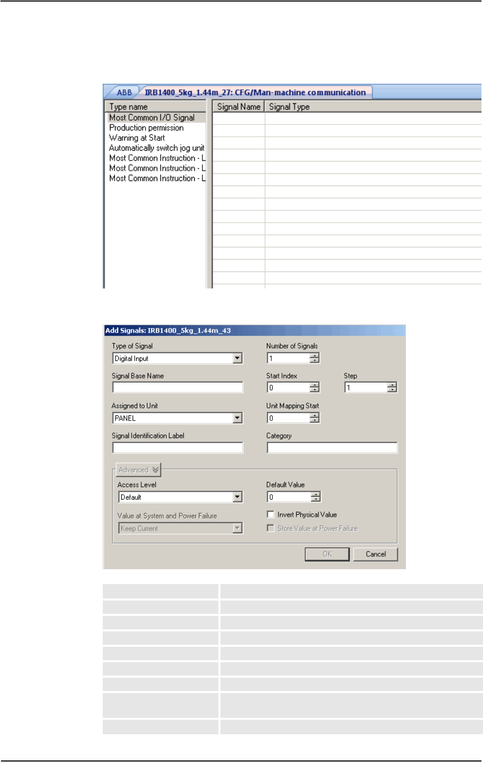
11 The Online and Offline Tabs
11.2.10. Configuration editor
3373HAC032104-001 Revision: D
© Copyright 2008-2010 ABB. All rights reserved.
Man-machine information
en0900000996
Add Signals
en0900000992
Type of Signal Defines the type of signal.
Signal Base Name Defines the name for one or more signals.
Assigned to Unit Defines the I/O unit to which the signal belongs.
Signal Identification Label Optionally, offers filtering and sorting based on this category.
Number of Signals Defines the number of signals to add in a range
Start Index Defines the index (number) to start the range with.
Step Defines the number which the index should increase with.
Unit Mapping Start Defines the bits in the I/O memory map of the assigned unit to
which the signal is mapped.
Category Optionally, offer filtering and sorting based on this category.
Continued
Continues on next page

11 The Online and Offline Tabs
11.2.10. Configuration editor
3HAC032104-001 Revision: D338
© Copyright 2008-2010 ABB. All rights reserved.
NOTE! You must have write access to the controller to be able to open the add signal
window.
Layout of the Instance editor
en0400000839
1. The Parameter list displays the parameters and their value for the open instance.
2. The Value box displays the type of parameter and the value of the parameter.
3. The Restriction box displays the restrictions for the parameter. The restrictions hasve
to be fulfilled to update the controller database.
4. The Limits box displays the limits for the parameter.
Access Level Defines the write access to I/O signals for categories of I/O
controlling clients connected to the robot controller.
Default Value Specifies the I/O signal value to be used at the start.
Value at System and
Power Failure
Specifies whether the output I/O signal should keep its current
value or take the I/O signal's default value in case of system
failure or at a power fail.
Store Value at Power
Failure
Specifies if the I/O signal should be set to the value stored in the
permanent memory pool or not at the start.
Invert Physical Value Applies an inversion between the physical value of the signal
and its logical representation in the system.
Icon Description
xx
Editable parameter
xx
Parameter that is not applicable for this instance and
therefore not editable.
xx
Parameter that is read-only.
Continued

11 The Online and Offline Tabs
11.2.11. Load Parameters
3393HAC032104-001 Revision: D
© Copyright 2008-2010 ABB. All rights reserved.
11.2.11. Load Parameters
Prerequisite
You must have write access to the controller.
Loading a configuration file
1. In the Online and Offline browser, select the system and expand the Configuration
node.
2. Click Load Parameters to bring up a dialog box.
3. In the dialog box, select how you want to combine the parameters in the configuration file
to load with the existing parameters:
4. Click Open and browse to the configuration file to load. Then click Open again.
5. In the information box, click OK to confirm that you want to load the parameters from
the configuration file.
6. When the loading of the configuration file is finished, close the Select mode dialog box.
If a restart of the controller is necessary for the new parameters to take affect, you will be
notified of this.
If you want to... then select...
replace the entire configuration of the topic
with the one in the configuration file.
Delete existing parameters before loading
add new parameters from the configuration
file to the topic, without modifying the existing
ones.
Load parameters if no duplicates
add new parameters from the configuration
file to the topic and update the existing ones
with values from the configuration file.
Parameters that only exist in the controller
and not in the configuration file will not be
changed at all.
Load parameters and replace duplicates

11 The Online and Offline Tabs
11.2.12. Save Parameters
3HAC032104-001 Revision: D340
© Copyright 2008-2010 ABB. All rights reserved.
11.2.12. Save Parameters
Overview
The system parameters of a configuration topic can be saved to a configuration file, stored on
the PC or any of its network drives.
The configuration files can then be loaded into a controller. They are thereby useful as
backups, or for transferring configurations from one controller to another.
File-naming conventions
The configuration files should be named with a name that relates to their corresponding
topics. When saving configuration files, the correct name for each file will be suggested by
default.
Saving a configuration file
1. In the Offline or Offline browser, select the system and expand the Configuration node.
2. Click Save Parameters and select the topic to save to a file and click Save.
3. In the Save As dialog box, browse for the folder to save the file in.
4. Click Save.
Saving several configuration files
1. Select the Configuration node.
2. Click Save System Parameters.
3. In the Save System Parameters dialog box, select the topics to save to files. Then click
Save.
4. In the Browse for Folder dialog box, browse for the folder to save the files in.
Then click OK.
The selected topics will now be saved as configuration files with default names in the
specified folder.

11 The Online and Offline Tabs
11.2.13. Safety Configuration
3413HAC032104-001 Revision: D
© Copyright 2008-2010 ABB. All rights reserved.
11.2.13. Safety Configuration
Overview
For information on safety configuration, see Application manual - SafeMove and Application
manual - Electronic Position Switches.

11 The Online and Offline Tabs
11.3.1. Add Controller
3HAC032104-001 Revision: D342
© Copyright 2008-2010 ABB. All rights reserved.
11.3 Online specific features
11.3.1. Add Controller
Connecting to a controller
You can connect to a controller in the following two ways:
• Add Controller - For adding available controllers to the network
• One Click Connect - For connecting to the service port of the controller
NOTE!
To use RobotStudio in Online mode for connecting to a real controller, the controller system
must have the option PC-interface.
Add a controller
1. In the Online tab, click Add Controller to bring up a dialog box in which all available
controllers are listed.
2. If the controller is not found in the list, type its IP address in the IP Address box, and then
click Refresh.
3. Select the controller in the list and click OK.
One Click Connect
It provides an easy way to connect to a robot controller.
The following are the prerequisites:
• Connect the computer to the controller service port.
• Ensure that the network settings on the PC is correct. DHCP should either be enabled
or the IP address should have a specific value. For more information on network
settings, see Network settings on page 141.
1. In the Online tab, click One Click Connect.
Adds the controller connected to the service port in a single step.

11 The Online and Offline Tabs
11.3.2. Request Write Access
3433HAC032104-001 Revision: D
© Copyright 2008-2010 ABB. All rights reserved.
11.3.2. Request Write Access
Overview
You need Write access for editing programs and configurations or in any other way to change
data on the controller.
Prerequisites for Write access
You can get Write access to any controller as long as the prerequisites are fulfilled.
If the prerequisites are not fulfilled you will be denied, or lose, the Write access. This means
that if you have Write access in auto mode and the controller is switched over to manual mode
you will lose the Write access without any warning. This is because the FlexPendant unit by
default has the Write access in manual mode, for safety reasons. The same will happen if the
remote Write access in manual mode is recalled from the FlexPendant unit.
Result
The Controller Status window will be updated when the request for Write access is granted.
If the Write access is denied, a message is displayed.
When the
Controller is in
Mode:
This has to be fulfilled:
Auto The Write access must not be taken by any other user.
Manual The remote Write access must be granted on the FlexPendant. For
safety reasons, a FlexPendant user can also recall this remote Write
access in manual mode.

11 The Online and Offline Tabs
11.3.3. Release Write Access
3HAC032104-001 Revision: D344
© Copyright 2008-2010 ABB. All rights reserved.
11.3.3. Release Write Access
Overview
Several users can be logged on to a single controller but only one can have the write access.
You can release the write access when you do not need it anymore.
Result
The Controller Status window will be updated when your access right has changed from read/
write to read only.

11 The Online and Offline Tabs
11.3.4. Authenticate
3453HAC032104-001 Revision: D
© Copyright 2008-2010 ABB. All rights reserved.
11.3.4. Authenticate
Overview
The data, functionality, and commands on a controller are protected by a User Authorization
system (also called UAS). The UAS restricts the parts of the system the user has access to.
Different users can have different access grants.
You can perform the following functions from the Authenticate menu:
• Login as a Different User
• Log off
• Log off all controllers
• Edit User Accounts
• UAS Grant Viewer
Login as a Different User
1. In the Authenticate menu, click Login as a Different User. The Add new user
dialog box appears.
2. In the User Name box, enter the user name you want to log on as.
3. In the Password box, enter the password for the user name you are logging on as.
4. Click OK.
Note: If you have previously logged on as a different user and wish to revert as default user,
click Login as Default User.
Log off
In the Authenticate menu, click Log off to log the user off from the controller.
Login off all controllers
In the Authenticate menu, click Log off to log the user off from all the controllers.
Edit User Accounts
For more information on User Accounts, see User Accounts on page 354.
UAS Grant Viewer
For more information on UAS Grant Viewer, see UAS Grant Viewer on page 359.

11 The Online and Offline Tabs
11.3.5. File transfer
3HAC032104-001 Revision: D346
© Copyright 2008-2010 ABB. All rights reserved.
11.3.5. File transfer
Overview
You can transfer the files and folders between the PC and a controller through the File
Transfer window.
Prerequisites
The following are the prerequisites to be met:
• The PC must be connected to the same network as the controller, or connected to the
service port of the controller.
• You must be logged on to the controller as a user with UAS grants that allows file
transferring.
Transferring files and folders
Use this procedure to transfer files and folders between the PC and a controller:
1. On the Online tab, click File Transfer.
The File Transfer window appears.
2. In the PC explorer, browse to the folder from or to which you want to transfer the data.
3. In the Controller explorer, browse to the folder from or to which you want to transfer the
data.
4. Select the item to transfer from the list.
To select several items at once, do one of the following:
To select then press
several adjacent items the SHIFT key and select the first and the last item.
several non-adjacent items the CTRL key and select each item.
all items in the list the keys CTRL + A
Continues on next page

11 The Online and Offline Tabs
11.3.5. File transfer
3473HAC032104-001 Revision: D
© Copyright 2008-2010 ABB. All rights reserved.
5. When the files and folder to transfer are selected, do one of the following:
6. Place the insertion point either in the PC explorer or the Controller explorer and click
CTRL + V.
NOTE!
In the PC explorer or Controller explorer window, right-click to view the following
context menu:
• Transfer
• One level up
• Open
• Refresh
• Cut
• Copy
• Paste
• Delete
• Remove
To then press
cut the files CTRL + X
copy the files CTRL + C, or click Arrow
Continued

11 The Online and Offline Tabs
11.3.6. FlexPendant Viewer
3HAC032104-001 Revision: D348
© Copyright 2008-2010 ABB. All rights reserved.
11.3.6. FlexPendant Viewer
Overview
FlexPendant Viewer is an add-in to RobotStudio that retrieves and displays a screenshot from
the FlexPendant. The screenshot is generated automatically at the moment of the request.
Prerequisites
The controller you want to retrieve screen shots from must be added to your robot view.
A FlexPendant must be connected to the controller. If no FlexPendant is currently connected
(option Hot plug is installed and the jumper plug is used) then no screen shot can be retrieved.
Using FlexPendant Viewer
1. Make sure you are connected to the controller.
2. Click FlexPendant Viewer.
A screen shot will be displayed in the workspace.
3. To reload the screen shot, click Reload in the workspace.
4. To set an automatic reload period for the screen shot, click on the menu Tools, point to
FlexPendant Viewer and click Configure.
Set the desired reload period and select the check-box Activated. Then click OK.
Results on the controller
The screenshot will automatically be saved as a file on the controller. When a new request is
sent, a new screenshot is generated and saved, overwriting the previous file.
No message will be displayed on the FlexPendant.

11 The Online and Offline Tabs
11.3.7. Import Options
3493HAC032104-001 Revision: D
© Copyright 2008-2010 ABB. All rights reserved.
11.3.7. Import Options
Importing system options
1. In the Online tab, click Import Options to bring up a dialog box.
2. In the Option source box, enter the path to the folder where the options to import are
located. You can also click the Browse button and browse to the folder.
3. In the Media Pool destination box, enter the path to the media pool you want to store the
options in. You can also click the Browse button and browse to the media pool folder.
4. Select the options to import and click Import.
To select several options at once, do one of the following:
5. Click OK.
Removing system options
1. In the Online tab, click Import Options to bring up a dialog box.
2. In the Media Pool destination list, enter the path to the media pool from which you want
to delete the options. You can also click the Browse button and browse to the media pool
folder.
3. Select the options to delete and click Remove.
To select several options at once, do one of the following:
4. Click OK.
To select then hold down
several adjacent options the SHIFT key and select the first and the last option.
several non-adjacent options the CTRL key and select each option.
To select then hold down
several adjacent options the SHIFT key and select the first and the last option.
several non-adjacent options the CTRL key and select each option.
11 The Online and Offline Tabs
11.3.8. Properties
3HAC032104-001 Revision: D350
© Copyright 2008-2010 ABB. All rights reserved.
11.3.8. Properties
Overview
You can perform the following from the Properties menu:
• Renaming the controller
• Setting the controller date and time
• Setting the Controller ID
• Viewing controller and system properties
• Handling the Device Browser
Renaming the controller
The controller name is an identification of the controller that is independent of the system or
the software running on the controller. Unlike the controller ID, the controller name does not
have to be unique for each controller.
NOTE!
The controller name must be written with characters from the ISO 8859-1 (Latin 1) character
set.
1. In the Properties menu, click Rename.
The Rename Controller dialog box appears.
2. Enter the new name of the controller in the dialog box.
3. Click OK.
The new name will be activated when the controller is restarted.
You will be prompted to either click Yes to restart the controller immediately or click No
to restart later.
Setting the controller date and time
You can either set the date and time to the same as the computer you are working from, or you
can specify the date and time manually.
Use this procedure to set the controller date and time:
1. In the Properties menu, click Date and Time.
The Set Date and Time dialog box appears.
2. In the Set Controller’s date and time, click the arrow next to the date and time list to set
the date and time of the controller.
NOTE!
Click Get local computer’s time to set the date and time of the controller to the same as the
computer you are working on.
Continues on next page

11 The Online and Offline Tabs
11.3.8. Properties
3513HAC032104-001 Revision: D
© Copyright 2008-2010 ABB. All rights reserved.
Setting the Controller ID
The Controller ID is by default set to the serial number of the controller and is thereby a
unique identifier of the controller.
The Controller ID is a unique identifier for the controller and should not be changed.
However, if the hard disk of the controller is replaced, the ID will be lost and you must set it
back to the serial number of the controller.
NOTE!
You must Request Write Access to the controller before setting the controller ID.
1. In the Properties menu, click Controller ID.
The Set Controller ID dialog box appears.
2. Enter the Controller ID and then click OK.
NOTE!
Use only characters from the ISO 8859-1 (Latin 1) character set and no more than 40
characters.
Viewing controller and system properties
You can view the following properties for a controller and its running sytem.
1. In the Properties menu, click Controller and System Properties.
The Controller and System Properties window appears.
2. In the Tree view at the left of the window, browse to the node for which you want to view
the properties.
The properties of the selected object are displayed in the Properties list to the right of the
window.
Viewing the Device Browser
The Device Browser displays the properties and trends of the various hardware and software
devices in a robot controller.
1. In the Properties menu, click Device Browser. The Device Browser window
appears.
2. In the Tree view at the left of the window, browse to the node for which you want to
view the properties. The properties of the selected object are displayed in the
Properties list to the right of the window.
Controller Properties System Properties
Boot Application Control Module
Controller ID Drive Module #1
Controller Name Serial Number
Installed Systems System Name
Network Connections
Continued
Continues on next page

11 The Online and Offline Tabs
11.3.8. Properties
3HAC032104-001 Revision: D352
© Copyright 2008-2010 ABB. All rights reserved.
Updating the tree view
1. Press F5, to update the tree view.
Displaying the properties of a device
1. Select a device in the tree view to view its properties or values in the right-hand panel.
Displaying a trend
1. Select a device in the tree view and then double-click any property in the right-hand
panel that has a numerical value to bring up a trend view. The trend view collects data
at a rate of one sample per second.
Hiding, stopping, starting or clearing a trend
1. Right-click anywhere in the trend view and then click the appropriate command.
Continued

11 The Online and Offline Tabs
11.3.9. Go Offline
3533HAC032104-001 Revision: D
© Copyright 2008-2010 ABB. All rights reserved.
11.3.9. Go Offline
Overview
The main purpose of this feature is to create a new station with a VC similar to the connected
real controller. This helps a robot technician to work offline, and not just when connected to
the real controller.
Using Go Offline
1. Connect the PC to a real controller.
2. On the Online tab, click Request Write Access.
For more information on Request Write Access, see Request Write Access on page 343.
3. Click Go Offline.
The Go Offline dialog box is displayed.
4. Enter a name for the system and browse for the location to save the system.
A new station is created with a VC with the same configuration as the real controller.
NOTE!
Go Offline transfers additional options from on a real controller and installs them on the PC.

11 The Online and Offline Tabs
11.3.10. User Accounts
3HAC032104-001 Revision: D354
© Copyright 2008-2010 ABB. All rights reserved.
11.3.10. User Accounts
Overview
All the procedures below require the following steps to be taken before managing the details:
1. In the Online browser, select the controller to which you want to manage a user or group
2. From the Online tab, click Request Write Access to provide write access to the
controller.
3. In the Online tab, click Authenticate and select Edit User Accounts, for administering
UAS accounts, grants, and groups.
Users tab
With the Users tab you set which users will be able to log on to the controller and which
groups the users shall belong to.
en0400001104
Users tab Parts
1. The Add button. Opens a dialog box for adding new users.
2. The Edit button. Opens a dialog box for changing the log on name and password of the
user.
3. The Delete button. Deletes the selected user account from the controller.
4. The Users on this Controller list. Shows the user accounts defined on this controller. The
list has two columns:
Column Description
User The name of the user account
Status Shows if the account is activated or deactivated. When deactivated,
it is not possible to log on using that account.
Continues on next page

11 The Online and Offline Tabs
11.3.10. User Accounts
3553HAC032104-001 Revision: D
© Copyright 2008-2010 ABB. All rights reserved.
5. The Activated/Deactivated item box. Changes the status of the user account.
6. The User’s groups/User’s grants list.
The User’s groups list shows which group(s) the user is a member of. For changing the
membership of a group, select or clear the checkbox in front of the group name.
The User’s grants list shows the available grants for the selected User’s group(s). When
selecting a grant from the User’s grants list, a description of the selected grant appears.
en0500001572
Adding a user
1. On the Users tab, click Add to bring up a dialog box.
2. In the User Name box, enter the user name. Use only characters from the ISO 8859-1
(Latin 1) character set and no more than 16 characters.
3. In the Password box, enter the user's password. The password you type in will not be
visible. Use only characters from the ISO 8859-1 (Latin 1) character set and no more than
16 characters.
4. In the Retype Password box, enter the user's password again.
5. Click OK to add the new user and close the dialog box.
6. Click OK.
Deleting a user
1. On the Users tab, select the user to delete from the Users on this controller list and click
Delete.
2. To the question Are you sure you want to remove this user?, answer Yes .
3. Click OK.
Continued
Continues on next page

11 The Online and Offline Tabs
11.3.10. User Accounts
3HAC032104-001 Revision: D356
© Copyright 2008-2010 ABB. All rights reserved.
Setting up group membership
1. On the Users tab, select the user from the Users on this controller list.
2. In the User’s groups list, select the groups the user shall be a member of.
3. Click OK.
Changing a name or password
1. On the Users tab, select the user to edit from the Users on this controller list and click
Edit user.
This opens the Edit dialog box.
2. To change the user name, enter the new name in the User Name box. Use only characters
from the ISO 8859-1 (Latin 1) character set and no more than 16 characters.
3. To change the password, enter the new password in the Password box, then retype the
password in the Retype Password box. Use only characters from the ISO 8859-1 (Latin
1) character set and no more than 16 characters.
4. Click OK to save the changes to the user and close the dialog box.
5. Click OK.
Activating or deactivating a user
1. On the Users tab, select the user from the Users on this controller list and click the status
text (Activated or Deactivated). An item box appears and you can change the status.
The user's new state is now displayed in the status column of the Users on this controller
list.
2. Click OK.
Continued
Continues on next page
11 The Online and Offline Tabs
11.3.10. User Accounts
3573HAC032104-001 Revision: D
© Copyright 2008-2010 ABB. All rights reserved.
Exporting a user list
1. On the Users tab, select the user from the Users for this Controller list and click Export.
This opens a Save as dialog box, in which you specify the name and location for the file
with the user list.
Importing a user list
1. On the Users tab, select the user from the Users for this Controller list and click Import.
This opens an Open file dialog box, in which you browse to the file with the list to import.
When you have selected the file, the ImportOptionsForm dialog appears.
Adding a group
1. On the Groups tab, click Add.
This opens the Add new group dialog box.
2. In the Group Name box, enter the name of the group. Use only characters from the ISO
8859-1 (Latin 1) character set and no more than 16 characters.
3. Click OK to add the new group and close the dialog box.
4. Click OK.
Renaming a group
1. On the Groups tab, select the group to rename from the Groups on this controller list
and click Rename.
This opens the Rename Group dialog box.
2. In the Group Name box, enter the name of the group. Use only characters from the ISO
8859-1 (Latin 1) character set and no more than 16 characters.
3. Click OK to rename the group and close the dialog box.
Select ... Description
Delete existing users and groups
before importing
Earlier groups and users will be deleted.
Advanced options A new dialog appears.
Import users but don’t replace duplicates means that
you will not replace the existing users.
Import users and replace duplicates means that you will
replace the existing users.
Import groups but don’t replace duplicates means that
you will not replace the existing groups.
Import groups and replace duplicates means that you
will replace the existing groups.
Continued
Continues on next page

11 The Online and Offline Tabs
11.3.10. User Accounts
3HAC032104-001 Revision: D358
© Copyright 2008-2010 ABB. All rights reserved.
4. You will now be asked if you want the users who belong to this group to continue
belonging to a group with the old name as well as the new one.
5. Click OK.
Deleting a group
1. On the Groups tab, select the group to delete from the Groups on this controller list and
click Delete.
2. You will now be asked if you want the users who belong to this group to continue
belonging to it though it is not valid.
3. Click OK.
Giving grants to a group
1. On the Groups tab, select the group from the Groups on this controller list.
2. In the Controller grants/Application grants list, select the grants to give to the group.
3. Click OK.
Click To
Yes Let the users of the group be members to groups with both the old and
the new name. However, the old group will no longer be defined in the
controller's UAS since it is replaced by the new group.
This option might be useful if you plan to recreate the old group, or copy
the user's settings to another controller who has the old group defined.
No Delete the user's memberships to the old group. This is to just replace
the old group name with the new one.
Cancel To cancel the change and keep the old group name, with its user's
memberships.
Click To
Yes Let the users of the group remain members to it even if it is no longer
defined in the controller's UAS.
This option might be useful if you plan to recreate the group, or copy
the user's settings to another controller who has the group defined.
No Delete the user's memberships to the group.
Cancel Cancel the change and keep the group, with its user's memberships.
Continued

11 The Online and Offline Tabs
11.3.11. UAS Grant Viewer
3593HAC032104-001 Revision: D
© Copyright 2008-2010 ABB. All rights reserved.
11.3.11. UAS Grant Viewer
Overview
The UAS Grant Viewer page displays information about the grants provided to the user
currently logged in and the groups owning them.
1. In the Authenticate menu, click UAS Grant Viewer. The UAS Grants window
appears.
en0900000852
Examples of common actions to perform
Action Necessary grants
Rename the controller
(A restart of the controller is necessary)
Modify controller properties
Remote warm start
Change system parameters and load configura-
tion files
Modify configuration
Remote warm start
Install a new system Administration of installed system
Perform a backup
(A restart of the controller is necessary)
Backup and save
Remote warm start
Restore a backup
(A restart of the controller is necessary)
Restore a backup
Remote warm start
Load/delete modules Load program
Create new module. Load program
Edit code in RAPID modules Edit RAPID code
Save modules and programs to disk Backup and save
Start program execution from Task Window Execute program
Continues on next page

11 The Online and Offline Tabs
11.3.11. UAS Grant Viewer
3HAC032104-001 Revision: D360
© Copyright 2008-2010 ABB. All rights reserved.
Controller grants
Create a new I/O signal, that is, add a new
instance of the type Signal
( A restart of the controller is necessary)
Modify configuration
Remote warm start
Set the value of an I/O signal I/O write access
Access to controller disks from File Transfer
window
Read access to controller disks
Write access to controller disks
Action Necessary grants
Full access This grant includes all controller grants, also new grants
added in future RobotWare versions. The grant does not
include any application grants or the Safety Controller con-
figuration grant.
Manage UAS settings Gives access to read and write the UAS configuration, that is
to read, add, remove and modify UAS users and groups.
Execute program Gives access to perform the following:
• Start/step program (stop is always allowed)
• Move PP to Main
• Execute service routines
Perform ModPos and HotEdit Gives access to perform the following:
• Modify or teach positions in RAPID code (ModPos)
• During execution modify positions in RAPID code as
single points or as a path (HotEdit)
• Restore ModPos/HotEdit positions to original
• Modify current value of any RAPID variable
Modify current value Gives access to modify current value of any RAPID variable.
This grant is a subset of the grant Perform ModPos and
HotEdit.
I/O write access Gives access to perform the following:
• Set I/O signal value
• Set signal as simulated and remove simulation
• Set I/O unit and bus as enabled/disabled
Backup and save Gives access to perform a backup and to save modules,
programs and configuration files.
Restore a backup Gives access to restore backup and perform B-start.
Modify configuration Gives access to modify the configuration database, that is to
load configuration files, change system parameter values
and add/delete instances.
Load program Gives access to load/delete modules and programs.
Remote warm start Gives access to perform warm start and shutdown from a
remote location. No grant is required to perform warm start
via a local device, as for example the FlexPendant.
Edit RAPID code Gives access to perform the following:
• Modify code in existing RAPID modules
• Frame calibration (tool, workobj)
• Commit ModPos/HotEdit positions to current values
• Rename program
Continued
Continues on next page

11 The Online and Offline Tabs
11.3.11. UAS Grant Viewer
3613HAC032104-001 Revision: D
© Copyright 2008-2010 ABB. All rights reserved.
Program debug Gives access to perform the following:
• Move PP to routine
• Move PP to cursor
• HoldToRun
• Activate/deactivate RAPID tasks
• Request write access from the FlexPendant
• Enable/disable non-motion execution
Decrease production speed Gives acces to decrease speed from 100% in Auto mode.
This grant is not required if speed is already below 100%, or
controller is in Manual mode.
Calibration Gives access to perform the following:
• Fine calibrate mechanical unit
• Calibrate base frame
• Update/clear SMB data
Note! Frame calibration (tool, wobj) requires the grant Edit
RAPID code. Manual offset of mechanical unit calibration
data and loading new calibration data from file require the
grant Modify configuration.
Administration of installed
systems
Gives access to perform the following:
• Install new system
•P-start
• I-start
•X-start
• C-start
• Select System
• Install system from device
This grant gives full FTP access, that is, the grant gives the
same rights as Read access to controller disks and Write
access to controller disks.
Read access to controller
disks
Gives external read access to controller disks. This grant is
only valid for explicit disk access, for example with an FTP
client or the File Manager of RoboStudio.
It is possible, for example, to load a program from /hd0a
without this grant.
Write access to controller
disks
Gives external write access to controller disks. This grant is
only valid for explicit disk access, for example with an FTP
client or the File Manager of RoboStudio.
It is possible, for example, to save a program to the controller
disk or perform a backup without this grant.
Modify controller properties Gives access to set controller name, controller ID and
system clock.
Delete log Gives access to delete messages in the controller Event
Log.
Revolution counter update Gives access to update the revolution counter.
Safety Controller configuration Gives access to perform a configuration of the Safety
Controller. This is valid only for the PSC-option and is not
included in the Full access grant.
Continued
Continues on next page

11 The Online and Offline Tabs
11.3.11. UAS Grant Viewer
3HAC032104-001 Revision: D362
© Copyright 2008-2010 ABB. All rights reserved.
Application grants
Access to the ABB menu on
FlexPendant
Value true gives access to the ABB menu on the Flex-
Pendant. This is the default value if a user does not have the
grant.
Value false means that the user cannot access the ABB
menu when the controller is in Auto mode.
The grant has no effect in Manual mode.
Log off FlexPendant user when
switching to Auto mode
A user having this grant is automatically logged off from the
FlexPendant when switching from Manual mode to Auto
mode.
Continued

11 The Online and Offline Tabs
11.4.1. Synchronize to Station
3633HAC032104-001 Revision: D
© Copyright 2008-2010 ABB. All rights reserved.
11.4 Offline specific features
11.4.1. Synchronize to Station
Synchronizing to the station
1. In the Offline tab, click Synchronize to Station to bring up a dialog box.
2. Select the paths to be synchronized to the station from the list.
3. Click OK.
The message Synchronization to Station completed is displayed in the Output window.

11 The Online and Offline Tabs
11.4.2. Synchronize to VC
3HAC032104-001 Revision: D364
© Copyright 2008-2010 ABB. All rights reserved.
11.4.2. Synchronize to VC
Synchronizing to the virtual controller
1. In the Offline tab, click Synchronize to VC to bring up a dialog box.
2. Select the elements to be synchronized to the VC from the list.
3. Click OK.
The message Synchronization to VC completed is displayed in the Output window.

11 The Online and Offline Tabs
11.4.3. Virtual FlexPendant
3653HAC032104-001 Revision: D
© Copyright 2008-2010 ABB. All rights reserved.
11.4.3. Virtual FlexPendant
Opening a Virtual FlexPendant
You can open a virtual FlexPendant in one of the following ways:
1. On the Offline tab, click Virtual FlexPendant.
2. Press the keyboard shortcut, CTRL + F5.
NOTE!
The Virtual FlexPendant is applicable while running a virtual controller.
For information on specifying the appearance and placement of virtual FlexPendant, see
Options:Robotics:Virtual Controller on page 185.

11 The Online and Offline Tabs
11.4.4. Run Mode
3HAC032104-001 Revision: D366
© Copyright 2008-2010 ABB. All rights reserved.
11.4.4. Run Mode
Overview
The Run Mode indicates the mode of the controller. It has the following two options
• Continuous
• Single
You can set the run mode of the controller in the following ways:
• On the Offline tab, click Run Mode and then click either Continuous or Single.
• On the Offline tab, click Rapid Tasks and then select Continuous or Single in the
Task window.
• On the Simulation tab, click Simulation Setup and then select Continuous or Single
in the Setup Simulation dialog box.

11 The Online and Offline Tabs
11.4.5. Control Panel
3673HAC032104-001 Revision: D
© Copyright 2008-2010 ABB. All rights reserved.
11.4.5. Control Panel
The Control Panel dialog box
Operation Mode This group contains the three operational modes of the
controller represented by option buttons.
Auto This option corresponds to the Auto mode on the FlexPendant.
Moving between the Auto and Manual Full Speed options
must proceed via the Manual option.
Manual This option corresponds to the Manual mode on the Flex-
Pendant.
Manual Full Speed This option corresponds to the Manual 100% mode on the Flex-
Pendant.
Moving between the Auto and Manual Full Speed options must
proceed via the Manual option.
Motors On Click this button to turn on the motors.
Enable Device In a manual mode, click this button to simulate holding the
enabling device to turn on the motors.
Release Device In a manual mode, click this button to turn off the motors.
Reset Emergency Stop If the controller enters the emergency stop state, click this button
to reset the state.

11 The Online and Offline Tabs
11.4.6. Shutdown
3HAC032104-001 Revision: D368
© Copyright 2008-2010 ABB. All rights reserved.
11.4.6. Shutdown
Shutting down a controller
1. In the Online or Offline browser, select the controller to shut down.
2. On the Offline tab, click Shutdown and select either Shutdown to close the connection
to the controller or Terminate Virtual Controllers to end all controller processes.
NOTE!
Suppose you want to restart the controller, select Warmstart. For more information on
restarting a controller, see Restart on page 330.

11 The Online and Offline Tabs
11.4.7. Set Task Frames
3693HAC032104-001 Revision: D
© Copyright 2008-2010 ABB. All rights reserved.
11.4.7. Set Task Frames
Modifying Task frame
1. In the Offline tab, click Set Task Frames.
The Modify Task Frames dialog box appears.
2. Set the reference to World, UCS, or Local.
3. Edit the position and orientation of task frames in the Task Frames coordinate box.
4. Click Apply.
To the question, Do you also want to move the Base Frames(s)?
• Click Ye s to move the base frame, but keeps its relative placement to the task frame.
• Click No. The following question appears Do you want to update the controller
configuration and restart?. Click Yes to restart the controller and update the base
frame configuration of the connected VC.
NOTE!
If there are any stationary RAPID objects (tooldata, workobjects) connected to the robot,
the following question appears Do you want to keep the positioning of all stationary
RAPID objects?
• Click Ye s to keep all the stationary RAPID objects in their global coordinates.
• Click No to move all the stationary RAPID objects along with the base frame (same
coordinates relative to base frame).

11 The Online and Offline Tabs
11.4.8. System Configuration
3HAC032104-001 Revision: D370
© Copyright 2008-2010 ABB. All rights reserved.
11.4.8. System Configuration
Overview
The system configuration window contains functions for making and viewing advanced
system configurations, such as changing controller and baseframe positions, calibrating and
setting up external axes.
The left side of the system configuration window contains a hierarchical tree with which you
browse to different aspects of the system. The right side contains a property sheet for the
aspect selected in the tree. Below are short descriptions of the property sheets for each aspect
node of the system configuration.
CAUTION!
Changing the system configurations may result in corrupted systems or unexpected robot
behaviors. Be sure to understand the effects of the changes before proceeding.
The System node
The system node contains a box with information about the system and a button for loading
new parameters (configuration files) to the system.
The task node
The task node has no property page.
The mechanism folder node
The property page of this node contains controls for mapping and setting axis and joints. It is
from this page you set up external axes.
The mechanism library node
The property page of this node contains controls for changing the baseframe of the robot or
mechanism. Here, too, you specify whether the baseframe is moved by another mechanism
(coordinated motion), like a track external axis.
Updating the baseframe position
1. Move the mechanical unit (robot or external axis) to its new location using the ordinary
tools for moving and placing objects.
2. In the Offline browser, select the controller for the mechanical unit.
3. Click System Configuration to bring up a dialog box.
NOTE! The System configuration dialog box can also be opened by:
• In the Paths&Targets browser, right-click a station.
• Select Configuration and click System Configuration.
4. Select the node for the mechanical unit in the hierarchical tree. The baseframe property
sheet for the robot is now displayed.
Continues on next page

11 The Online and Offline Tabs
11.4.8. System Configuration
3713HAC032104-001 Revision: D
© Copyright 2008-2010 ABB. All rights reserved.
5. Select the baseframe position values to use after restarting the robot.
6. Click OK.
NOTE!
For information on adding a track from System Configuration, see Setting up a system with
track motion of type RTT or IRBTx003 manually on page 69.
Select To
Controller values Reset all changes to the baseframe made since the last time the
system was started.
Stored station values Reset all changes made to the baseframe since the last time the
station was saved.
Optionally, you can enter new values in the baseframe
coordinate boxes (relative to the controller world coordinate
system).
Use current station
values
Read and use the current location of the baseframe.
Optionally, you can enter new values in the baseframe
coordinate boxes (relative to the controller world coordinate
system).
Continued

11 The Online and Offline Tabs
11.4.9. Encoder Unit
3HAC032104-001 Revision: D372
© Copyright 2008-2010 ABB. All rights reserved.
11.4.9. Encoder Unit
Configuring an Conveyor Encoder Unit
1. Click Encoder Unit.
The Configure Conveyor Encoder Unit dialog box appears.
NOTE! The Configure Conveyor Encoder Unit dialog box can also be opened by:
• In the Paths&Targets browser, right-click a station.
• Select Configuration and click Encoder Unit.
2. Select CNV1 from the Mechanical Unit list.
3. In the Parameters box, enter the values for Maximum Distance, Minimum Distance,
Queue Tracking Distance and Start Window Width.
NOTE!
If any of the parameter values are changed, the controller must be restarted.
4. Click OK.
5. Click Yes to restart the controller.

12 The Add-Ins Tab
12.1. Overview
3733HAC032104-001 Revision: D
© Copyright 2008-2010 ABB. All rights reserved.
12 The Add-Ins Tab
12.1. Overview
The Add-Ins tab
The Add-Ins tab contains the control for PowerPacs and the VSTA.

12 The Add-Ins Tab
12.2. Visual Studio Tools for Applications
3HAC032104-001 Revision: D374
© Copyright 2008-2010 ABB. All rights reserved.
12.2. Visual Studio Tools for Applications
Building an add-in
1. Click Visual Studio Tools for Applications.
2. Create a new project or open an existing one. Compose or edit as required.
3. To build the add-in, from the Build menu, click Build.
The add-in will be loaded in RobotStudio and appear as a user add-in in the Add-In
browser.
4. Save the project to your hard disk if you want the add-in to remain with the user.
Otherwise, open a station, right-click in the Add-In browser and then click Add to
Station.

13 The Context Menus
13.1. Add to Path
3753HAC032104-001 Revision: D
© Copyright 2008-2010 ABB. All rights reserved.
13 The Context Menus
13.1. Add to Path
Creating a move instruction based on an existing target
1. Select the target for which to create the move instruction.
2. From the Home menu, in the Path Programming group, select the type of move
instruction to create.
3. Click Add to Path.
The move instruction will appear under the path node as a reference to the original target.

13 The Context Menus
13.2. Align Frame Orientation
3HAC032104-001 Revision: D376
© Copyright 2008-2010 ABB. All rights reserved.
13.2. Align Frame Orientation
The Align Frame Orientation dialog box
Reference Specify the frame or target for which you want to align the
selected objects here.
Align Axis The axis you specify here will be aligned as on the reference
target/frame for all selected objects.
Lock Axis The axis you specify here will not be changed on the selected
objects by the align function, but will keep its orientation.
13 The Context Menus
13.3. Align Target Orientation
3773HAC032104-001 Revision: D
© Copyright 2008-2010 ABB. All rights reserved.
13.3. Align Target Orientation
Aligning target orientation
1. Select the targets whose orientation you wish to change.
2. Click Align Target Orientation to bring up a dialog box.
3. In the Reference box, specify the target whose orientation you want to use as reference,
by first click in the box and then selecting the target either from the graphics view or the
Layout browser.
4. In the Align Axis box, select the axis whose orientation you want to copy from the
reference target to the selected ones.
5. In the Lock Axis box, select the axis to rotate the target around. The orientation of this
axis will not be changed on the targets. For example, if the Z axis of all targets are
orientated normally to the surface of the work piece and you want to keep it this way, you
should lock the Z axis.
6. Click Apply.
TIP!
You can change the Align and Lock axis and click Apply again to reorientate the targets until
you deselect them.

13 The Context Menus
13.4. Attach to
3HAC032104-001 Revision: D378
© Copyright 2008-2010 ABB. All rights reserved.
13.4. Attach to
Attaching an object
1. In the Layout browser, right-click the child object, click Attach to and click the parent
object in the list.
Attaching an object by drag and drop
1. In the Layout browser, drag the child object to the parent object.
2. In the displayed message, click the corresponding button:
To Click
attach the child object and move it to the
attachment point
Yes
attach the child object and keep its position No
not perform the attachment Cancel

13 The Context Menus
13.5. Auto Configuration
3793HAC032104-001 Revision: D
© Copyright 2008-2010 ABB. All rights reserved.
13.5. Auto Configuration
Setting a robot axis configuration for all targets in a path
1. In the Paths&Targets browser, select a path and then click AutoConfiguration. The
robot now steps through each target in the path and sets the configurations.
2. If the first target in the path has no configuration assigned, the one closest to the robot’s
current configuration will be used. If the first target has a configuration assigned, the
assigned one will be used. Thus, the result of the autoconfiguration may vary depending
on the first target’s configuration.
13 The Context Menus
13.6. Check Reachability
3HAC032104-001 Revision: D380
© Copyright 2008-2010 ABB. All rights reserved.
13.6. Check Reachability
Checking the reachability
1. In the Paths&Targets browser, select the task that contains the targets or move
instructions to check.
2. Click Reachability to open a dialog box. Make sure that the Check reachability for
targets, paths, move instructions check box is selected.
Optionally, select or clear the Check reachability for targets, paths, move instructions
check box for showing and hiding the reachability display.
3. In the Layout browser, select the objects whose reachability you want to check. If paths
are selected, the reachability will be checked for all move instructions in each path.
4. In the Reachability dialog box, click Add.
The frames for the selected objects will now change color based on their reachability
status.
Color Means
Green The object can be reached.
Yellow The object can be reached at its current position, but not at its
current orientation
Red The object cannot be reached at its current position.

13 The Context Menus
13.7. Configurations
3813HAC032104-001 Revision: D
© Copyright 2008-2010 ABB. All rights reserved.
13.7. Configurations
Manually setting a robot axis configuration for single targets
1. In the Paths&Targets browser, select a target and then click Configurations to bring up
a dialog box.
2. If more than one configuration solution exist, examine them by clicking them, one at a
time.
The position of the robot with the selected configuration will be displayed in the graphics
window, and the joint values for the configuration will be displayed in the joint values list
below the configurations list.
In most cases, selecting a configuration similar to the previous one is the best choice.
3. Select the configuration to use and click Apply.

13 The Context Menus
13.8. Convert Frame to Workobject
3HAC032104-001 Revision: D382
© Copyright 2008-2010 ABB. All rights reserved.
13.8. Convert Frame to Workobject
Converting a frame to a workobject
1. In the Layout browser, select a frame.
2. Click Convert Frame to Workobject. The new workobject will appear in the
Paths&Targets browser.
3. Optionally, rename or edit the workobject in any way.

13 The Context Menus
13.9. Convert to Move Circular
3833HAC032104-001 Revision: D
© Copyright 2008-2010 ABB. All rights reserved.
13.9. Convert to Move Circular
Prerequisites
At least two targets, the via-point target and the end point target, must have been created.
A path containing at least the via-point target and the end point target, in correct order, must
have been created.
Converting to Move Circular
1. In the Paths&Targets browser, expand the path node that contains the move instruction
to be converted.
2. Select the move instruction that contains the via-point of the circular motion together with
the succeeding move instruction, which will serve as the end point. You can select several
instructions by holding down the SHIFT key while clicking the instructions.
3. Click Convert to Move Circular. The two selected move instructions will be converted
to a circular move instruction, which includes the via-point and the end point.
TIP!
To convert two move instructions to a circular motion, you can also select and right-click both
move instructions at once and then click Convert to Circular.

13 The Context Menus
13.10. Copy / Apply Orientation
3HAC032104-001 Revision: D384
© Copyright 2008-2010 ABB. All rights reserved.
13.10. Copy / Apply Orientation
Copying and applying an orientation
1. In the browser, select the object or target from which to copy the orientation.
2. On the Modify menu, click Copy Orientation.
3. In the browser, select the object or target to which to apply the orientation.
4. On the Modify menu, click Apply Orientation. This can be performed on several targets
or a group of selected targets.

13 The Context Menus
13.11. Detach
3853HAC032104-001 Revision: D
© Copyright 2008-2010 ABB. All rights reserved.
13.11. Detach
Detaching an object
1. In the Layout browser, right-click the attached object (child) and then click Detach. The
child will be detached from the parent and return to its position before the attachment.

13 The Context Menus
13.12. Execute Move Instruction
3HAC032104-001 Revision: D386
© Copyright 2008-2010 ABB. All rights reserved.
13.12. Execute Move Instruction
Prerequisites
The move instruction must exist.
A virtual controller must be running for the robot with the move instruction.
Executing a move instruction
1. In the Paths&Targets browser, browse to the motion instruction to execute through the
Controller, Tasks and Paths nodes.
2. Click Execute move instruction. The TCP of the active robot will move from the current
location to the motion instruction according to the programed motion properties. If the
target for the motion instruction does not have a stored configuration, the robot will use
the configuration nearest the current one.

13 The Context Menus
13.13. Graphic Appearance
3873HAC032104-001 Revision: D
© Copyright 2008-2010 ABB. All rights reserved.
13.13. Graphic Appearance
Overview
With the graphic appearance dialog box you set the graphic properties for an individual
object. The settings made here override the generic settings made in the options dialog box.
The dialog box contains one view group where you select the part of the object to affect, and
three tabs with settings.
Graphic Appearance: The View group
Graphic Appearance: The Rendering tab
Graphic Appearance: The Colors tab
Selection Select the parts of the object whose appearance you wish to
change. When Body or Surface/Curve is selected, you select
the object to work with in the preview display.
NOTE! To change the appearance of a part:
1. On the Modify menu, click Graphic Appearance. A
color box with the following options appears - Metals,
Light colors, medium colors, Dark colors.
2. Select any of the options to change the appearnace.
Backface culling Select this check box to view only the front sides (the direction
of the positive normal) of the faces in the model. This improves
the graphics performance and indicates the directions of the
faces in the model.
Clear this check box to also display the back sides of the faces
in the model. This ensures that the model is displayed correctly
even if the faces are in the wrong direction. If a model with faces
in the wrong direction is used for programming, you might get
unpredicted results.
Twosided lightning Select this check box to light the object from two sides.
Clear this check box to light the object from one side.
Flat shade Select this check box to change the appearance of shades.
Flip normals Click this button to change the direction of all faces on the
model.
Line width Specify the width of lines in the object here.
The detail level options Select the detail level of the model here. Only the levels
selected in the Options dialog box when the object was created
or imported are available.
Simple Color Click this color box to select another color for the object.
Transparency Use this slider to control the transparency of the object.
The color boxes Set the color of the object for different light situations here.
Shininess Specify the reflectiveness of the object here.
Continues on next page

13 The Context Menus
13.13. Graphic Appearance
3HAC032104-001 Revision: D388
© Copyright 2008-2010 ABB. All rights reserved.
Graphic Appearance: The Textures tab
Effect Specifies the type of graphic effect to be used on the selected
part.
• Basic : Simple texturing/environment mapping or just a
solid color.
• Anisotropic: Brushed metal effect simulating an
anisotropic light model
• Bump Mapping: Texture that specifies the bumpiness of
the surface
• Parallex Mapping: Improved version of bump mapping
NOTE! Anisotropic, Bump Mapping and Parallex Mapping
requires DirectX9-class hardware to be correctly displayed in
the 3D window.
Base texture Specifies the basic structure of the selected part. It is a standard
24-bit image displayed on a 3D surface.
Environment map Provides a highly reflective appearance to the surface.
Normal/Bump Map Specifies a texture that defines the bumpiness of the surface.
NOTE! This option is enabled only during Bump mapping and
Parallex mapping effect.
Blend with material Select this check box to blend the texture with the colors and
properties specified on the Material tab.
Swap u/v Click this button to swap the horizontal and vertical directions of
the texture.
Modify Select along which directions the commands listed below shall
be applied.
u is the horizontal axis of the texture.
v is the vertical axis of the texture.
Normalize Click this button to set the ratio between the dimensions of the
object and the texture to 1.
Flip Click this button to invert the coordinates along the selected
axes. This is the same as mirroring around the other axis.
Stretch Click this button to stretch the texture along the selected axes.
Shrink Click this button to shrink the texture along the selected axes.
Shift < Click this button to move the texture along the selected axes.
Shift> Click this button to move the texture along the selected axes.
Continued

13 The Context Menus
13.14. Interpolate Path
3893HAC032104-001 Revision: D
© Copyright 2008-2010 ABB. All rights reserved.
13.14. Interpolate Path
Reorienting targets in a path by interpolation
1. In the Layout browser or the graphics window, select the path with the targets to reorient.
2. Click Interpolate Path. to bring up a dialog box.
3. With the Interpolate type options, select whether to use Linear or Absolute
interpolation.
Linear interpolation distributes the difference in orientation evenly, based on the targets
positions along the length of the path. By contrast, absolute interpolation distributes the
difference in orientation evenly, based on the targets’ sequence in the path.
4. If using the Select Start/End option, select the start and end targets for the interpolation
in the Start target and End target boxes, respectively.
5. Optionally, with the Lock Axis options, select an axis to lock.
6. Click Apply.

13 The Context Menus
13.15. Invert
3HAC032104-001 Revision: D390
© Copyright 2008-2010 ABB. All rights reserved.
13.15. Invert
Inverting the direction of a face
1. Right-click in the Modeling browser, point to Filter and make sure that both Show
Bodies and Show Faces are selected.
2. In the Modeling browser, expand the node for the object and browse down to and select
the face which direction you want to invert.
3. In the Modeling browser, expand the node for the object and browse down to and select
the face whose direction you want to invert.
4. Click Invert. If the option backface culling is activated, the face will now shift from
visible to not visible, or the other way around, depending on from which direction you
view the face. If backface culling is deactivated, there will be no visible indication that the
direction of the face has been inverted.

13 The Context Menus
13.16. Jump to Target
3913HAC032104-001 Revision: D
© Copyright 2008-2010 ABB. All rights reserved.
13.16. Jump to Target
Jumping to a target
1. In the Paths&Targets browser, browse to the target to jump to through the Controller,
Tasks and WorkObjects nodes.
2. Click Jump to target.
If the target has a valid configuration for the robot axes stored, the active TCP of the robot
will immediately be positioned at the target. If no valid configuration is stored, the Select
Robot configuration dialog box is displayed.
3. In the Select Robot Configuration dialog box, select a suitable configuration solution
and click Apply. The selected configuration is now stored with the target.
NOTE!
You can deactivate the configuration check when jumping to targets. The robot will then use
the configuration solution closest to the current one when reaching the target. For more
information, see RobotStudio Options on page 182.

13 The Context Menus
13.17. Linked Geometry
3HAC032104-001 Revision: D392
© Copyright 2008-2010 ABB. All rights reserved.
13.17. Linked Geometry
Overview
The Linked Geometry feature allows you to load geometry from a shared repository. If the
source file is updated, then the station will be updated with a single click.
Adding Link
You can add a link to a geometry in two ways:
1. In the Home tab, click Import Geometry to open a dialog box.
Select the option Link to Geometry.
2. In the Layout browser, right-click an existing part in the station and select Add Link.
A dialog box opens where you can select the CAD file to be linked.
Editing Link
To edit an existing link:
1. In the Layout browser, right-click an existing part in the station.
2. Select the option Link to Geometry and click Edit Link.
Deleting Link
To delete an existing link:
1. In the Layout browser, right-click an existing part in the station.
2. Select the option Link to Geometry and click Delete Link.
Updating Linked Geometry
To update a linked geometry:
1. In the Layout browser, right-click an existing part in the station, component group or the
station.
2. Select the option Link to Geometry and click Update Linked Geometry.
The update result is displayed in the output window.
NOTE! When you select a component group or a station, all linked geometries within the
group or station is updated.
NOTE! If the timestamp on the file is newer than the timestamp stored in the station, all
corresponding parts will be updated from the source location.

13 The Context Menus
13.18. The Library Group
3933HAC032104-001 Revision: D
© Copyright 2008-2010 ABB. All rights reserved.
13.18. The Library Group
Modifying a library component
1. In the Layout browser, select the library you wish to modify.
2. Click Disconnect Library.
3. Select the library and then make any modifications to it.
4. Select the modified library, and then click Save As Library.

13 The Context Menus
13.19. Mechanism Joint Jog
3HAC032104-001 Revision: D394
© Copyright 2008-2010 ABB. All rights reserved.
13.19. Mechanism Joint Jog
Jogging the joints of a robot
1. In the Layout browser, select the robot.
2. Click Mechanism Joint Jog to bring up a dialog box.
3. Each row in the Jog Joints dialog box represents a joint of the robot. Jog the joints either
by clicking and dragging the bar at each row, or by using the arrows to the right of each
row.
Set the length of each step in the Step box.
The Mechanism Joint Jog dialog box
Joint Move the joints of the objects by dragging the slider on the row
corresponding to each joint. Alternatively, click the buttons to
the right of the row, or type a value.
Cfg The current configuration value.
TCP The current position of the TCP.
Step Specify the length of the joint movements for each click of the
buttons to the right of each joint row.
External Axis If the robot uses external axes, you can select an axis to jog
from this list. The external axes must belong to the same task
as the object you are jogging for occurring in this list. If no
external axes are present in the same task, this list is not
available.
Lock TCP Select this check box to reposition the robot according to the
jogging of the external axis.
For track-external axes the robot will reposition so that the TCP
is locked relative to the world coordinate system.
For positioner-external axes the robot will reposition so that the
position of the robot’s TCP is locked relative to the attachment
point of the positioner. The robot will move with the positioner
the same way as when using multi-robot jog.
If no external axes are present in the same task, this check box
is not available.
External axes joint Move the joint of the external axes by dragging the slider on the
row corresponding to each joint. Alternatively, click the buttons
to the right of the row, or type a value.
If no external axes are present in the same task, this check box
is not available.
Continues on next page

13 The Context Menus
13.19. Mechanism Joint Jog
3953HAC032104-001 Revision: D
© Copyright 2008-2010 ABB. All rights reserved.
Jogging a conveyor
1. Create Empty Path. See Empty Path on page 207.
2. In the Layout browser, select the conveyor.
3. Right-click Conveyor Mechanism and select Mechanical Joint Jog.
The Joint Jog dialog box appears.
4. Jog the conveyor by moving the slider and click Teach Instruction.
A move instruction is added to the path.
NOTE!
When you jog the conveyor mechanism, objects on the conveyor are also moved.
• If you jog the conveyor mechanism beyond the maximum distance, the workobject
will be dropped.
• If you jog the conveyor mechanism beyond the zero position, the workobject that
belongs to the first part is attached to the conveyor attachment point.
If the workobject is dropped in Teach Mode, you can jog the conveyor backwards to connect
it again.
Continued

13 The Context Menus
13.20. Mechanism Linear Jog
3HAC032104-001 Revision: D396
© Copyright 2008-2010 ABB. All rights reserved.
13.20. Mechanism Linear Jog
Jogging the TCP of a robot by using the Linear Jog dialog box
1. In the Layout browser, select the robot.
2. Click Mechanism Linear Jog to bring up a dialog box.
3. Each row in the Linear Jog dialog box represents a direction or rotation for the TCP. Jog
the TCP along the preferred direction or rotation, either by clicking and dragging the bar
at each row, or by using the arrows to the right of each row.
4. From the Reference list, you can select the coordinate system that you want to jog the
robot relative to.
5. In the Step box, specify the step movement per deg/rad.

13 The Context Menus
13.21. Mirror Path
3973HAC032104-001 Revision: D
© Copyright 2008-2010 ABB. All rights reserved.
13.21. Mirror Path
The Mirror Path dialog box
Duplicate Select this option to keep the existing path when mirroring.
Replace Select this option to remove the existing path after mirroring.
X-Y, X-Z and Y-Z Select the plane to mirror the path around with these options.
The plane is defined by the selected axes and position of the
reference coordinate system selected below.
Reference Select the frame or coordinate system to define the mirror plane
in.
To use another frame than any of the predefined ones, select
Select Frame from the list and specify the frame in the box
below.
Select Frame If Select Frame is used as Reference frame, specify the frame
to use here by first clicking in the box and then selecting the
frame from the graphics window or the Layout browser.
Flip axis X/YZ Select one of these options to mirror the orientation of the
targets. When any of these are selected, the robot will approach
the targets in a mirrored way.
The axis you select will change the most for achieving the
mirrored orientation, while the other one will be kept as near to
its current direction as possible.
The axis that is set to the robot’s approach vector cannot be
selected.
Keep orientation Select this option to keep the orientation of the targets. When
selected, the robot will go to the mirrored position, but approach
the target from the same direction as for the original target.
Mirror Robot Configura-
tion
Select this option to also mirror the robot axis configuration for
the targets. Selecting this option will mirror the robot’s motions
completely.
For using this option, the following conditions must be met:
• The Reference frame must be set to Baseframe.
• The Mirror plane must be set to X-Z.
• The tool of each move instruction must have its TCP in
the X-Z plane of tool0.
• All targets in the path must have robot axis configuration
set.
• The virtual controller must be running.
More / Less Click this button to show or hide the commands for naming and
location of generated targets and paths.
New path name Specify the name of the path that will be generated by the
mirroring here.
Target prefix Specify a prefix for the targets that will be generated by the
mirroring here.
Receiving robot Specify the robot task in which the new targets and path shall be
created.
Receiving work object Specify the work object in which the new targets shall be
created.

13 The Context Menus
13.22. Mirror
3HAC032104-001 Revision: D398
© Copyright 2008-2010 ABB. All rights reserved.
13.22. Mirror
Mirroring a part
1. In the Layout browser, select the part to mirror and right-click.
2. Select Mirror and then click one of the following options from the context menu:
NOTE!
The mirror feature is applicable only to objects of type body and part that contains geometry.
Parts and and bodies that are imported without geometry cannot be mirrored. See
Mathematical versus graphical geometries on page 28.
For information on mirroring a path, see Mirror Path on page 397.
select... to create a new part..
Mirror YZ around YZ plane
Mirror ZX around ZX plane
Mirror XY around XY plane

13 The Context Menus
13.23. Modify Curve
3993HAC032104-001 Revision: D
© Copyright 2008-2010 ABB. All rights reserved.
13.23. Modify Curve
Extending a curve with a straight line in the direction of the curve’s tangent
1. Click Modify curve to bring up a dialog box.
2. Select Extend as modify method and then click the curve segment, close to the
appropriate vertex.
Note that when you rest the pointer over the curve the endpoint closest to the pointer is
highlighted. This is the endpoint that will be selected for extension when you click the
curve.
3. In the Distance from endpoint box, enter the length of the extension. In the graphics
window a yellow line displays a preview of the extension.
4. Click Apply.
Joining curves
1. Click Modify curve to bring up a dialog box.
2. Select Join as modify method and then click the curves to join in the graphics window.
The curves may be either intersecting or adjacent to be joined.
The Selected curves list displays the curves that will be joined. To remove a curve from
the list, select the list entry and press the DEL key.
3. In the Tolerance list, enter a value in millimeters. Adjancent curves whose end points lie
within the tolerance will be valid for the operation.
4. Click Apply.
Projecting curves on a surface
1. Click Modify curve to bring up a dialog box.
2. Select Project as modify method and then click the curves to project in the graphics
window.
Note that when you rest the pointer over the curve, the projection direction is displayed.
The project direction is always the negative Z direction of the User Coordinate System.
To change the projection direction, create a new frame with the desired orientation and set
it as user coordinate system.
The Selected curves list displays the curves that will be projected. To remove a curve
from the list, select the list entry and press the DEL key.
3. Click in the Target bodies list and then click the bodies to project on in the graphics
window. The bodies must be in the projection direction and be big enough to cover the
projected curves.
To remove a bodies from the list, select the list entry and press the DEL key.
4. Click Apply. A new curve will now be created in a new part, wrapped around the surface
of the selected bodies.
Continues on next page

13 The Context Menus
13.23. Modify Curve
3HAC032104-001 Revision: D400
© Copyright 2008-2010 ABB. All rights reserved.
Reversing curves
1. Click Modify curve to bring up a dialog box.
2. Select Reverse as modify method and then click the curves to reverse in the graphics
window.
Note that when resting the pointer over a curve, the current direction of the curve is
displayed by yellow arrows.
The Selected curves list displays the curves that will be reversed. To remove a curve from
the list, select the list entry and press the DEL key.
3. Click Apply. The curves will now be reversed.
Splitting a curve
1. Click Modify curve to bring up a dialog box.
2. Select Split as modify method and then click the curve at the point to split at. Only open
curves can be split.
Note that when you rest the pointer over the curve, point of the split is highlighted. This
point is affected by the current snap mode setting.
3. Click Apply. The curve will now be split to two separate curves in the same part.
Trimming a curve
1. Click Modify curve to bring up a dialog box.
2. Select Trim as modify method and then click the curve segment to trim.
Note that when you rest the pointer over the curve, the closest vertices are highlighted.
The segment between these points will be trimmed.
3. Click Apply. The selected part of the curve will now be removed.
Generic content of the Modify Curve dialog box
Extend Extend a curve at any vertex with a straight line in the direction
of the curve’s tangent.
Join Join two or more curves into one. The original curves will be
deleted when joining curves.
Project Project a curve onto a surface or a body, creating a new curve
on the target part.
Reverse Reverse the direction of curves.
Split Split a curve in two bodies. Only open curves can be split.
Trim Cut a segment of a curve between intersection or end points.
Continued
Continues on next page

13 The Context Menus
13.23. Modify Curve
4013HAC032104-001 Revision: D
© Copyright 2008-2010 ABB. All rights reserved.
Extend-specific information
Join-specific information
Selected curve Display the name of the curve to extend. Select the curve by
clicking it in the graphics window.
Note that when you rest the pointer over the curve the endpoint
closest to the pointer is highlighted. This is the endpoint that will
be selected for extension when you click the curve.
xx0600002637
Endpoint to extend Display the position of the endpoint to extend. To change the
endpoint, select the curve again, but click it closer to the other
endpoint.
Distance from endpoint Type the length of the extension here. You can also click a point
in the graphics window to set the length.
A yellow line indicates the length of the extension.
xx0600002638
Selected curves Display the names of the curves to join. Select the curves by
clicking them in the graphics window. To remove a curve from
the list, select the list entry and press the DEL key.
The curves may be either intersecting or adjacent to be joined.
Tolerance Specifies the distance within which the end points of adjacent
curves may lie to be joined.
Continued
Continues on next page

13 The Context Menus
13.23. Modify Curve
3HAC032104-001 Revision: D402
© Copyright 2008-2010 ABB. All rights reserved.
Project-specific information
Reverse-specific information
Selected curve Display the name of the curves to project. Select the curves by
clicking them in the graphics window.
Note that when you rest the pointer over the curve the projection
direction is displayed. The project direction is always the
negative Z direction of the User Coordinate System. To change
the projection direction, create a new frame with the desired
orientation and set it as user coordinate system.
xx0600002639
Target bodies Display the name of the bodies to project the curve on. Select
the bodies by first clicking in the box and then clicking the bodies
in the graphics window.
Selected curves Display the names of the curves to reverse. Select the curves
by clicking them in the graphics window.
Note that when resting the pointer over a curve the current
direction of the curve is displayed by yellow arrows.
xx0600002640
Continued
Continues on next page

13 The Context Menus
13.23. Modify Curve
4033HAC032104-001 Revision: D
© Copyright 2008-2010 ABB. All rights reserved.
Split-specific information
Trim-specific information
Selected curve Display the name of the curve to split. Select the curve by
clicking it in the graphics window.
Note that when you rest the pointer over the curve, the point
where the split will be is highlighted. This point is affected by the
current snap mode setting.
xx0600002641
Point on curve These boxes show the position of the split point. To change the
split point, select the curve again, but click another part of it.
Selected curve Display the name of the curve to trim. Select the curve by
clicking it in the graphics window.
Note that when you rest the pointer over the curve the closest
vertexes are highlighted. It is the segment between those points
that will be cut.
xx0600002642
Trim only works on single curves with intersection points. If you
want to trim a curve that intersects with another curve, first join
the two curves.
First section endpoint Display the position of the first trimming point.
Second section endpoint Display the position of the second trimming point.
Continued

13 The Context Menus
13.24. Modify External Axis
3HAC032104-001 Revision: D404
© Copyright 2008-2010 ABB. All rights reserved.
13.24. Modify External Axis
Modifying external axis positions in targets
1. Select the targets (one or several) you want to modify, either in the Layout browser or in
the graphics window. If you select several targets, the values you specify will be applied
to all selected targets.
2. Click Modify External Axis to bring up a dialog box.
3. Edit the values of the axis by performing any of the following:
4. Click Apply.
The Modify External Axis dialog box
Action Description
Type a new position value
for an axis
In the Eax column, select the value of the external axis you want
to edit, and enter the new value.
Jog the axis to the new
position
Use the arrow buttons to the left of the Joint Values column for
jogging the axis. Then click the right arrow button between the
Joint values column and the Eax column to transfer the current
joint value to the Eax value.
< Jog the joint of the external axis corresponding to each row by
clicking the < button.
> Jog the joint of the external axis corresponding to each row by
clicking the > button.
value box Enter the axis value for the corresponding joint of the external
axis in the value box.
<- With the arrow left button, you transfer the value from the Eax
box to the corresponding value box.
-> With the arrow right button, you transfer the value from the value
box to the corresponding Eax box.
Eax Specify the value of the corresponding joint of the external axis.

13 The Context Menus
13.25. Modify Instruction
4053HAC032104-001 Revision: D
© Copyright 2008-2010 ABB. All rights reserved.
13.25. Modify Instruction
Modifying an instruction
1. In the Paths&Targets browser, select the instruction you want to modify. If you want to
apply the same properties to several instructions, press the CTRL key and select them.
2. Click Modify Instruction to bring up a dialog box.
3. For move instructions, select joint or linear motion in the Motion type list.
4. In the Instruction Argument group, modify the values for the instruction.
For details about each argument, see the selected instruction in the RAPID Reference
Manual. For an overview of the arguments for move instructions, see below.
5. When you have finished modifying, click Apply.
Arguments for move instructions
The table below is an overview of common arguments for move instructions. For detailed
information about the arguments, see the selected instruction in the RAPID Reference
Manual.
To set the Use
subsequent instructions to be executed at once. \Conc
destination target for the instruction target. ToPoint
speed for the tool center point, the tool reorientation and
external axes.
Speed
velocity of the TCP in mm/s directly in the instruction (it will be
substituted for the corresponding speed data).
\V
total time in seconds during which the robot moves (it will be
substituted for the corresponding speed data).
\T
size of the generated corner path. Zone
position accuracy of the robot TCP directly in the instruction (the
length of the path will be substituted for the corresponding zone
specified in the zone data).
\Z
tool used for the movement (the TCP of this tool will be
positioned at the destination target).
\Tool
workobject to which the robot position in the instruction belongs. \Wobj


13 The Context Menus
13.27. Modify Tooldata
4073HAC032104-001 Revision: D
© Copyright 2008-2010 ABB. All rights reserved.
13.27. Modify Tooldata
Modifying tooldata
1. In the Layout browser, select the tooldata you want to modify.
2. Click Modify Tooldata to bring up a dialog box.
3. In the Misc Data group:
• Modify the Name of the tool.
• Select if the tool is to be held by the robot in the Robot holds tool list.
4. In the Tool Frame group:
• Modify the Position x, y, z of the tool.
• Modify the Rotation rx, ry, rz of the tool.
5. In the Load Data group:
• Enter a new Weight for the tool.
• Modify the Center of gravity for the tool.
• Modify the Inertia for the tool.
6. In the Sync Properties group:
• In the Storage type list, select PERS or TASK PERS. Select TASK PERS if you
intend to use the tooldata in MultiMove mode.
• In the Module list, modify the module in which to declare the tooldata.
7. Click Apply.

13 The Context Menus
13.28. Modify Workobject
3HAC032104-001 Revision: D408
© Copyright 2008-2010 ABB. All rights reserved.
13.28. Modify Workobject
Modifying a workobject
1. In the Layout browser, select the workobject you want to modify.
2. Click Modify Workobject. to bring up a dialog box.
3. In the Misc Data group, modify the values for the workobject:
• Enter a Name for the workobject.
• In the Robot holds workobject list, select True or False. If you select True, the robot
will move the work piece instead of the tool.
• In the Moved by mechanical unit list, select the mechanical unit with which the robot
movements are coordinated. This setting is only valid when Programmed has been
set to False.
• In the Programmed list, select True or False. True means that the workobject will
use a fixed coordinate system, and False that a movable coordinate system (that is,
coordinated external axes) will be used.
4. In the User Frame group, do one of the following:
• Modify the user frame by entering values for the Position x, y, z and the Rotation rx,
ry, rz for the workobject. Click in one of these boxes, and then click the position in
the graphics window to transfer the values.
• Modify the user frame by using the Frame by points dialog box, see Frame from
Three Points on page 197 .
5. In the Object Frame group, do one of the following:
• Modify the object frame by selecting values for Position x, y, z and Rotation rx, ry,
rz for the workobject.
• Modify the object frame by using the Frame by points dialog box.
6. In the Sync Properties group, modify the values for the workobject:
• In the Storage type list, select PERS or TASK PERS
. Select TASK PERS if you
intend to use the workobject in MultiMove mode.
• In the Module list, select the module in which to declare the workobject.
7. Click Apply.
NOTE!
If you change the position of a workobject that is used in a program, you have to synchronize
the affected paths to the virtual controller; otherwise, the program will not be updated.

13 The Context Menus
13.29. Move Along Path
4093HAC032104-001 Revision: D
© Copyright 2008-2010 ABB. All rights reserved.
13.29. Move Along Path
Prerequisites
At least one path must have been created in the station.
A virtual controller must be running for the robot to move along the path.
Moving along a path
1. In the Paths&Targets browser, select the path to move along.
2. Click Move along path. In the graphics window, the robot will move along the path.

13 The Context Menus
13.30. Move to Pose
3HAC032104-001 Revision: D410
© Copyright 2008-2010 ABB. All rights reserved.
13.30. Move to Pose
Prerequisites
At least one joint position must be defined.
Only one mechanism may be selected at a time.
Moving to a pose
1. In the Layout browser, select one mechanism to move.
2. Click Move to Pose and then click one of the available poses. In the graphics window, the
mechanism will move to the pose.
13 The Context Menus
13.31. Place
4113HAC032104-001 Revision: D
© Copyright 2008-2010 ABB. All rights reserved.
13.31. Place
Placing an item
1. Select the item you want move.
2. Click Place and then click one of the commands to bring up a dialog box.
3. Set the reference coordinate system you want to use.
4. Click the points in the graphics window to transfer values to the from-point boxes to the
to-point boxes. For detailed information, see the tables below.
5. Click Apply.
The Place Object by One Point dialog box
If you want to move the item Choose
from one position to another without affecting
the orientation of the object.
Select the axes to be affected.
One Point
according to the relationship between a start
and a finish line.
The object will move to match the first point,
then it will rotate to match the second point.
Two Points
according to the relationship between a start
plane and a finish plane.
The object will move to match the first point,
then it will rotate to match the third point.
Three Points
from one position to a target or frame position
and simultaneously change the orientation of
the object according to the frame orientation.
The position of the object changes according
the orientation of the to-point coordinate
system.
Frame
from one frame of reference to another Two Frames
Reference Select the reference coordinate system to which all positions or
points will be related.
Primary Point - From Click in one of these boxes, and then click the primary point in
the graphics window to transfer the values to the Primary Point
- From boxes.
Primary Point - To Click in one of these boxes, and then click the primary point in
the graphics window to transfer the values to the Primary Point
- To boxes.
Translate along these
axes
Select whether the translation is to be performed along the X, Y
or Z axis, or several of the axes.
Continues on next page

13 The Context Menus
13.31. Place
3HAC032104-001 Revision: D412
© Copyright 2008-2010 ABB. All rights reserved.
The Place Object by Two Points dialog box
The Place an Object by Three Points dialog box
The Place Object with Frame dialog box
Reference Select the reference coordinate system to which all positions or
points will be related.
Primary Point - From Click in one of these boxes, and then click the primary point in
the graphics window to transfer the values to the Primary Point
- From boxes.
Primary Point - To Click in one of these boxes, and then click the primary point in
the graphics window to transfer the values to the Primary Point
- To boxes.
Point on X-Axis - From Click in one of these boxes, and then click the point on the x axis
in the graphics window to transfer the values to the Point on X-
Axis - From boxes.
Point on X-Axis - To Click in one of these boxes, and then click the point on the x axis
in the graphics window to transfer the values to the Point on X-
Axis - To boxes.
Translate along these
axes
Select whether the translation is to be performed along the X, Y
or Z axis, or several of the axes.
Reference Select the reference coordinate system to which all positions or
points will be related.
Primary Point - From Click in one of these boxes, and then click the primary point in
the graphics window to transfer the values to the Primary Point
- From boxes.
Primary Point - To Click in one of these boxes, and then click the primary point in
the graphics window to transfer the values to the Primary Point
- To boxes.
Point on X-Axis - From Click in one of these boxes, and then click the point on the x axis
in the graphics window to transfer the values to the Point on X-
Axis - From boxes.
Point on X-Axis - To Click in one of these boxes, and then click the point on the x axis
in the graphics window to transfer the values to the Point on X-
Axis - To boxes.
Point on Y-Axis - From Click in one of these boxes, and then click the point on the y axis
in the graphics window to transfer the values to the Point on Y-
Axis - From boxes.
Point on Y-Axis - To Click in one of these boxes, and then click the point on the y axis
in the graphics window to transfer the values to the Point on Y-
Axis - To boxes.
Translate along these
axes
Select whether the translation is to be performed along the X, Y
or Z axis, or several of the axes.
Select Frame Specify the name of the frame with which you want to place the
object.
Continued
Continues on next page

13 The Context Menus
13.31. Place
4133HAC032104-001 Revision: D
© Copyright 2008-2010 ABB. All rights reserved.
The Place by Two Frames dialog box
From Select the frame object (For example, Target, Workobject,
Tooldata or Frame) from this dropdown list to set the From point
of moving the object.
To Select any of the frame object (For example, Target,
Workobject, Tooldata or Frame) from this dropdown list to set
the To point of moving the object.
Continued

13 The Context Menus
13.32. Remove Unused Targets
3HAC032104-001 Revision: D414
© Copyright 2008-2010 ABB. All rights reserved.
13.32. Remove Unused Targets
Removing unused targets
1. In the Paths&Targets browser, select either the Controller node or the Task node from
which you wish to remove the unused targets, and then click Remove Unused Targets.
2. To the question Are you sure you want to remove unused targets?, answer Yes . All
targets that not are used by any move instructions are now removed.

13 The Context Menus
13.33. Rename Targets
4153HAC032104-001 Revision: D
© Copyright 2008-2010 ABB. All rights reserved.
13.33. Rename Targets
Renaming targets
1. In the Paths & Targets browser, select the targets to rename.
To rename all targets in one or several paths, select the paths that contain the targets.
2. Click Rename targets to bring up a dialog box.
3. In the Target Prefix box, enter a text string to precede the target numbers.
4. Optionally, in the Increment box and the Start with box, change the numbering series for
the target names.
5. Optionally, in the Target Suffix box, enter a text string to follow the target numbers.
6. Click Apply.

13 The Context Menus
13.34. Reverse Path
3HAC032104-001 Revision: D416
© Copyright 2008-2010 ABB. All rights reserved.
13.34. Reverse Path
The commands
Simple Here you reverse only the target sequence. The new path will keep the
move instruction for each path segment and just reverse the
programed positions.
xx0500002041
Note that move instructions are not changed, just the targets. Even the
MoveAbsJ instruction to the joint target is preserved, but placed last.
Advanced Both target sequence and move instructions are reversed in a way that
corresponds to recording the robot movements and playing the movie
backwards. For example, if the robot used a linear motion to move from
a target, it will use a linear motion to move to the target after the
reversal.
xx0500002042
Note that the move instructions have changed together with the
targets. For example, in the original path, a joint motion was used to
reach target 20 and a linear motion to leave it. After the reversal there
is a linear motion to the target and joint motion from it.
Also, note that the jointtarget has been converted into an ordinary
target; otherwise, it would not be possible to program a linear motion
to that position.

13 The Context Menus
13.35. Rotate
4173HAC032104-001 Revision: D
© Copyright 2008-2010 ABB. All rights reserved.
13.35. Rotate
Rotating an item
1. Select the item you want to rotate.
2. Click Rotate to bring up a dialog box.
3. Select the reference coordinate system you want to use:
4. Specify the rotation of the item in the Rotate around x, y, z by first clicking in one of the
boxes, and then click the center position in the graphics window to transfer the values.
5. If you have selected the coordinate system User defined axis, specify the Axis start point
x, y, z and the Axis end point x, y, z.
6. Specify the Rotation of the item and the axis around which the rotation is to occur.
7. Click Apply.
If you want to move the item Select
absolute in the coordinate system of the
station
World
relative to the coordinate system of its parent Parent
relative to its own coordinate system Local
relative to the user-defined system UCS
relative to an axis defined by two points User defined axis

13 The Context Menus
13.36. Rotate Path
3HAC032104-001 Revision: D418
© Copyright 2008-2010 ABB. All rights reserved.
13.36. Rotate Path
Rotating a paths
1. In the Layout browser or the graphics window, select the paths to rotate.
2. Click Rotate path to bring up a dialog box.
3. In the Reference frame list, select the frame to rotate the paths around.
4. If Selected frame was selected in the Reference frame list, specify a frame or target in
the text box by clicking in the box and then selecting the frame in the graphics window.
5. With the Rotation axis options, select the axis of the frame to rotate around.
6. In the Rotation angle box, enter the rotation.
7. Click Apply.
Select To
World rotate around the station’s world coordinate system
Baseframe rotate around the robot’s baseframe
UCS rotate around a frame or target that previously has been set to
User Coordinate System.
Select Frame rotate around an existing target or frame other than the listed
ones. When using Select Frame, specify the frame to rotate
around further down.

13 The Context Menus
13.37. Set Local Origin
4193HAC032104-001 Revision: D
© Copyright 2008-2010 ABB. All rights reserved.
13.37. Set Local Origin
Setting the origin of the local coordinate system
1. If the object you want modify is a library component, first disconnect it from the library.
2. In the Layout browser or the graphics window, select the part to modify.
3. Click Set Local Origin to bring up a dialog box.
4. In the Set Local Origin dialog box, select the reference coordinate system you want to
use:
5. In the Position X, Y, Z boxes, either type the new position or, select it by first clicking in
one of the value boxes and then clicking the point in the graphics window.
6. Type the Orientation.
7. Click Apply.
If you want to move Select
relative to the part’s current local coordinate
system
Local
relative to the coordinate system of its parent Parent
absolute in the coordinate system of the
station
World
relative to a user-defined coordinate system UCS

13 The Context Menus
13.38. Set Normal to Surface
3HAC032104-001 Revision: D420
© Copyright 2008-2010 ABB. All rights reserved.
13.38. Set Normal to Surface
Setting the target orientation normal to a surface
1. In the Paths & Targets browser, select the target to modify.
2. Click Set Normal To Surface to bring up a dialog box.
3. On the Selection Level toolbar, set the selection level.
• To align the target to a specific surface, set the selection level to surface.
• To align the target to a specific point at the surface, set the selection level to part.
4. In the graphics window, click the reference surface. This will transfer the name of the part
or surface to the Surface box.
5. In the Approach Direction, click the button for the axis to be used as the approach
direction.
6. To set the distance between the surface and the target in the approach direction, specify
an Offset value.
7. Click Apply.

13 The Context Menus
13.39. Set Position
4213HAC032104-001 Revision: D
© Copyright 2008-2010 ABB. All rights reserved.
13.39. Set Position
Positioning an item
1. Select the item you want to move.
2. Click Set Position to bring up a dialog box.
3. In the Set Position dialog box, select the reference coordinate system you want to use:
4. In the Position X, Y, Z boxes, either type the new position, or select it by first clicking in
one of the value boxes and then clicking the point in the graphics window.
5. Specify the Orientation for the item.
6. Click Apply.
If you want to move the item Select
relative to its own coordinate system Local
relative to the coordinate system of its parent Parent
absolute in the coordinate system of the
station
World
relative to a user-defined coordinate system UCS

13 The Context Menus
13.40. Tool Compensation
3HAC032104-001 Revision: D422
© Copyright 2008-2010 ABB. All rights reserved.
13.40. Tool Compensation
Offsetting a path to compensate for tool radius
1. In the Paths&Targets browser or the graphics window, select the path.
2. Click Tool Compensation to bring up a dialog box.
3. In the Distance box, enter the size of the compensation (normally, the tool radius).
4. Using the Direction options, select whether the new path shall be on the left or the right
side of the current path.
5. Click Apply.

13 The Context Menus
13.41. Translate Path
4233HAC032104-001 Revision: D
© Copyright 2008-2010 ABB. All rights reserved.
13.41. Translate Path
Translating a path
1. In the Paths&Targets browser or the graphics window, select the paths to translate.
2. Click Translate path to bring up a dialog box.
3. In the Reference frame list, select the coordinate system to use as reference for moving
the paths.
4. If Select frame was selected in the Reference frame list, specify a frame or target in the
text box by clicking in the box and then selecting the frame from the graphics window.
5. In the Translation vector box, specify the distance to move the path along the X, Y and
Z axes of the reference frame.
Translation vector is applicable only if a reference frame is used. If Point to Point is used
as reference, specify the start and end points for the translation, instead. To do this, click
in one of the boxes for the point to specify and then select the point in the graphics
window, or type the coordinates of the point.
6. Click Apply.
Select To
World move relative to the origin of the world coordinate system
Base Frame move relative to the origin of the robot’s baseframe
UCS move relative to the origin of a frame or target that previously
has been set to User Coordinate System.
Select Frame move relative to the origin of an existing target or frame other
then the listed ones. When using Select Frame, specify the
frame to use further down.
Point to Point move the path from one point to another without specifying
any coordinate system.

13 The Context Menus
13.42. View Robot at Target
3HAC032104-001 Revision: D424
© Copyright 2008-2010 ABB. All rights reserved.
13.42. View Robot at Target
Viewing a robot at a target
1. Click View Robot at Target.
2. Select a target, either in the Paths&Targets browser or in the graphics window.
3. The robot will be shown at each selected target whenever a target is selected. By stepping
through the targets in the browser, it will be easy to see how the position of the robot
changes.
4. To turn the function off, click the command again.

13 The Context Menus
13.43. View Tool at Target
4253HAC032104-001 Revision: D
© Copyright 2008-2010 ABB. All rights reserved.
13.43. View Tool at Target
Viewing a tool at a target
1. Click View Tool at Target and select the tool you want to view at the target.
2. Select a target, either in the Paths&Targets browser or in the graphics window. You can
also multiselect targets to show several copies of the tool.
A copy of the tool will be shown at the selected target. By stepping through the targets in
the browser, it is easy to see how the tool orientation changes.
3. To turn the function off, click the command and clear the check box.

13 The Context Menus
13.43. View Tool at Target
3HAC032104-001 Revision: D426
© Copyright 2008-2010 ABB. All rights reserved.

14 The ScreenMaker tab
14.1.1. Overview
4273HAC032104-001 Revision: D
© Copyright 2008-2010 ABB. All rights reserved.
14 The ScreenMaker tab
14.1 Introduction to ScreenMaker
14.1.1. Overview
What is ScreenMaker?
ScreenMaker is a tool in RobotStudio for developing custom screens. It is used to create
customized FlexPendant GUIs without the need to learn Visual Studio development
environment and .NET programming.
Why ScreenMaker?
A customized operator interface on the factory floor is the key to a simple robotic system. A
well-designed custom operator interface presents the right amount of information at the right
time and in the right format to the user.
GUI concepts
xx080000226
A GUI makes it easier for people to work with industrial robots by presenting a visual front
end to the internal workings of a robotic system. For FlexPendant GUI applications, the
graphical interface consists of a number of screens, each occupying the user window area (the
blue box in the figure above) of the FlexPendant touch screen. A FlexPendant screen is then
Continues on next page

14 The ScreenMaker tab
14.1.1. Overview
3HAC032104-001 Revision: D428
© Copyright 2008-2010 ABB. All rights reserved.
composed of a number of smaller graphical components in a design layout. Typical controls
(sometimes referred as widgets or graphic components) include buttons, menus, images, and
text fields.
A user interacts with a GUI application by:
• Clicking a button
• Selecting from a menu
• Typing a text in a text box
• Scrolling
An action such as clicking a button is called an event. Whenever an action is performed, an
event is sent to the GUI application. The exact content of an event is solely dependent on the
graphic component itself. Different components trigger different types of events. The GUI
application responds to the events in the order generated by the user. This is called event-
driven programming, since the main flow of a GUI application is dictated by events rather
than being sequential from start to finish. Due to the unpredictability of the user’s actions, one
major task in developing a robust GUI application is to ensure that it works correctly no
matter what the user does. Of course, a GUI application can, and actually does, ignore events
that are irrelevant.
The event handler holds sets of actions to be executed after an event occurs. Similar to trap
routines in the RAPID program, the event handler allows the implementation of application-
specific logic, such as running a RAPID program, opening a gripper, processing logic or
calculating.
In summary, from a developer’s point of view, a GUI consists of at least two parts:
• the view part: layout and configuration of controls
• the process part: event handlers that respond to events
xx0800000227
Modern GUI development environments often provide a form designer, a (What You See Is
What You Get ) WYSIWYG tool to allow the user to select, position and configure the
widgets. As for event handlers, typically the developer must use a special programming
language recommended by the development environment.
Continued
Continues on next page

14 The ScreenMaker tab
14.1.1. Overview
4293HAC032104-001 Revision: D
© Copyright 2008-2010 ABB. All rights reserved.
FlexPendant concepts
xx0800000228
Running Windows CE, the ABB FlexPendant has limited CPU power and memory compared
to a PC. A custom GUI application must therefore be placed in the designated folders on the
controller hard drive before being loaded. Once loaded, it can be found in the ABB menu as
seen in the figure above. Clicking the menu item will launch the GUI application.
As the robot controller is the one actually controlling the robot and its peripheral equipment
by executing a RAPID program, a GUI application needs to communicate with the RAPID
program server in order to read and write RAPID variables and set or reset I/O signals.
It is essential for RAPID programmers to understand that there are two different levels
controlling a work cell: an event-driven GUI application running on the FlexPendant, and a
sequential RAPID program running in the controller. These reside on different CPUs and use
different operating systems, so communication and coordination are important and must be
carefully designed.
Continued

14 The ScreenMaker tab
14.1.2. Development environment
3HAC032104-001 Revision: D430
© Copyright 2008-2010 ABB. All rights reserved.
14.1.2. Development environment
Overview
This section presents an overview of the ScreenMaker development environment.
en0900000584
Parts Description
1 Ribbon Displays group of icons organized in a logical sequence of
functions. See Ribbon on page 431.
2 Project explorer Shows the active screen project and lists the screens that
are defined in the project. For more information, see
Managing ScreenMaker projects on page 442.
3 Design area Layout to design the screen with the available controls. For
more information, see Form designer on page 453.
4 Output window Displays information about the events that occur during
ScreenMaker development.
5 Too lBox Displays a list of available controls. For more information.
see ToolBox on page 432.
6 Properties window Contains the available properties and events of the
selected control(s). The value of the properties can either
be a fixed value or a link to an IRC5 data or an Application
Variable. For more information, see Properties window on
page 434.
7 Arrange Displays icons for resizing and positioning controls on the
design area. See Arrange on page 431.
Continues on next page

14 The ScreenMaker tab
14.1.2. Development environment
4313HAC032104-001 Revision: D
© Copyright 2008-2010 ABB. All rights reserved.
Ribbon
The ScreenMaker ribbon tab contains a group of icons organized in a logical sequence of
functions that facilitates the user in managing ScreenMaker projects.
en0900000452
The Ribbon is categorized into the following groups:
Arrange
This toolbar displays icons for resizing and positioning controls on the design area.
NOTE: The icons are enabled once you select a control or group of controls on the design
area.
en0900000592
Group Description
Project Facilitates the user to manage ScreenMaker project. See
Managing ScreenMaker projects on page 442.
Add Facilitates the user to add screen and application variables. See
Managing screens on page 445 and Managing application
variables on page 452.
Build Facilitates the user to build a project. See Building a project on
page 450.
Controller Facilitates the user to connect and deploy to the controller. See
Connecting to controller on page 449 and Deploying to
controller on page 451.
Arrange Facilitates the user to resize and position the controls on the
design area. See Arrange on page 431.
Close Facilitates the user to close a project.
Continued
Continues on next page

14 The ScreenMaker tab
14.1.2. Development environment
3HAC032104-001 Revision: D432
© Copyright 2008-2010 ABB. All rights reserved.
ToolBox
ToolBox acts a container for holding all the available controls that can be placed on a screen.
en0900000407
Continued
Continues on next page

14 The ScreenMaker tab
14.1.2. Development environment
4333HAC032104-001 Revision: D
© Copyright 2008-2010 ABB. All rights reserved.
The following table displays the GUI controls that can be dragged on to the design area.
NOTE!
For more information on using these controls and their properties, see the section Building
the user interface on page 435 and the chapterUsing the FlexPendant SDK of the Application
manual - FlexPendant SDK.
Control Description
ActionTrigger Allows to run a list of actions when either a signal or rapid data
changes
BarGraph Represents an analog value in a bar
Button Represents a control that can be clicked.
Provides a simple way to trigger an event, and is commonly
used to execute commands. It is labeled either with text or an
image.
CheckBox Allows multiple selections from a number of options. They are
displayed as a square box with white space (for unselected) or
as a tick mark (for selected).
ComboBox Represents a control that enables to select items from a list
Combination of a drop-down list and a textbox. It allows you to
either type a value directly into the control or choose from the
list of existing options.
CommandBar Provides a menu system for a ScreenForm
ControllerModeStatus Displays the mode of the Controller (Auto - Manual)
DataEditor Represents a text box control that can be used to edit the data.
Graph Represents a control that plots data with lines or bars.
GroupBox Represents a Windows control that displays a frame around a
group of controls with an optional caption.
Is a container used to group a set of graphic components. It
usually has a title at the top.
LED Displays a two states value, like a Digital Signal.
ListBox Represents a control to display a list of items.
Allows the user to select one or more items from a list contained
within a static, multiple line text box.
NumEditor Represents a text box control that can be used to edit a number.
When the user clicks it, a Numpad is opened.
NumericUpDown Represents a spin box that displays numeric values.
Panel Used to group collection of controls.
PictureBox Represents a picture box control that displays images.
RadioButton Allows to select only one of a predefined set of options.
RapidExecutionStatus Displays the execution status of the Controller Rapid Domain
(Running - Auto)
RunRoutineButton Represents a Windows button control that calls a RapidRoutine
when clicked
Switch Displays and lets change a two states value, like a Digital
Output Signal.
TabControl Manages a set of tab pages.
TpsLabel Very commonly used widget that displays text, a label is usually
static, that is, it has nointeractivity. A label generally identifies a
nearby text box or other graphic component.
Continued
Continues on next page

14 The ScreenMaker tab
14.1.2. Development environment
3HAC032104-001 Revision: D434
© Copyright 2008-2010 ABB. All rights reserved.
Properties window
A control is characterized by its properties and events. Properties describe the appearance and
behavior of the component, while events describe the ways in which a control notifies its
internal state change to others. By changing the value of a property, the controls have a
different look and feel, or exhibit different behavior.
en0900000408
Element Description
1 Graphical component name panel Displays the selected component, and lists the
available components of the active design
screen.
2 Properties window toolbar
en0900000409
1. Organizes table panel in categories
2. Organizes table panel alphabetically
3. Displays Properties in table panel
4. Displays Events in table panel
3 Table panel Displays all the properties or events in two-
columns. The first column shows the property
or event name, the second shows the value of
the property or name of the event handler.
4 Information panel Display information about a property or event.
Continued
Continues on next page

14 The ScreenMaker tab
14.1.2. Development environment
4353HAC032104-001 Revision: D
© Copyright 2008-2010 ABB. All rights reserved.
Editing the property value
You can edit the property value of a control from theProperties window in three ways:
Building the user interface
This section describes building the GUIs using the following controls from the ToolBox.
ActionTrigger
An action trigger initiates an event, such as making a hidden object visible when an action is
performed using a control. It allows to run a list of actions when the property value changes.
The property value can be bound to a signal, rapid data, or application variable.
ActionTrigger control can also be used to invoke the application from RAPID.
Use this procedure to add an ActionTrigger control::
1 By typing the numerics, strings and text.
For example, Location, Size, Name etc.
en0900000631
2 By selecting the predefined values from the
list. For example, BackColor, Font etc.
en0900000633
3 By entering the values in the dialog box.
For example, Enabled, States, BaseValue
etc.
en0900000632
Action
1 Drag an ActionTrigger control from the ToolBox on to the design area.
Continued
Continues on next page

14 The ScreenMaker tab
14.1.2. Development environment
3HAC032104-001 Revision: D436
© Copyright 2008-2010 ABB. All rights reserved.
NOTE: An action is not triggered when the screen is launched for the first time, but is
triggered when there is a difference in the bound value at any point of time. This functionality
is supported only in RobotWare 5.12.02 or higher.
Example: Consider a signal being bound to the value property. The value of the signal
changes at runtime on performing a specific action. The event handler configured for
ActionTrigger control gets triggered based on this signal value change.
2 You can modify the name, set the default value and configure data binding value for
a ActionTrigger control.
• To set the values of a property, see Properties window on page 434.
• You can set the trigger event for an ActionTrigger to any of the event handler
created either from a control or from an Events Manager option. To set up the
events, see Setup Events on page 453.
• To configure the data binding values, see Configuring data binding on page
459.
• To set the application variables, see Managing application variables on page
452.
en0900000629
en0900000630
Action
Continued
Continues on next page

14 The ScreenMaker tab
14.1.2. Development environment
4373HAC032104-001 Revision: D
© Copyright 2008-2010 ABB. All rights reserved.
TpsLabel
TpsLabel is a standard Windows label that displays a descriptive text.
Use this procedure to add a TpsLabel control:
NOTE!
• The controls Button, PictureBox, and TpsLabel support AllowMultipleStates.
• For more information on how to use AllowMultipleStates, see Picture object and
changing images due to I/O on page 477.
Panel
Panel is used to group a collection of controls.
Use this procedure to add a Panel control:
Step Action
1 Drag a TpsLabel control from the ToolBox on to the design area.
2 You can set the values, setup events, configure data binding values and set the
application values for a TpsLabel control.
• To set the values of a property, see Properties window on page 434.
• To set up the events, see Setup Events on page 453.
• To configure the data binding values, see Configuring data binding on page
459.
• To set the application variables, see Managing application variables on page
452.
3 You can set the option Allow Multiple States to true and change the property.
1. Click Allow Multiple States. The StatesEditor dialog box appears.
2. Click the check-box Allow Multi-States, select the properties to change from
Properties For States and click OK.
en0900000499
Step Action
1 Drag a Panel control from the ToolBox on to the design area.
2 You can add a group of controls to a panel.
Continued
Continues on next page

14 The ScreenMaker tab
14.1.2. Development environment
3HAC032104-001 Revision: D438
© Copyright 2008-2010 ABB. All rights reserved.
NOTE: Currently only EventHandler, CancelEventHandlers, and MouseEventArgs are
supported.
ControllerModeStatus
ControllerModeStatus displays the mode of the controller (Auto - Manual).
Use this procedure to add a ControllerModeStatus control:
3 You can modify the name, set the default value and binding value for a Panel control.
• To set the values of a property, see Properties window on page 434.
• To set up the events, see Setup Events on page 453.
• To configure the data binding values, see Configuring data binding on page
459.
• To set the application variables, see Managing application variables on page
452.
Step Action
Step Action
1 Drag a ControllerModeStatuscontrol from the ToolBox on to the design area.
2 You can set the values, setup events, configure data binding values, and set the
application variables for a ControllerModeStatus control.
• To set the values of a property, see Properties window on page 434.
• To set up the events, see Setup Events on page 453.
• To configure the data binding values, see Configuring data binding on page
459.
• To set the application variables, see Managing application variables on page
452.
3 You can select the image to be displayed when the controller is in Auto mode and in
Manual mode.
• Click AutoImage in the Properties window and browse to select the image to
be displayed in Auto mode.
• Click ManualImage in the Properties window and browse to select the image
to be displayed in Manual mode.
en0900000536
Continued
Continues on next page

14 The ScreenMaker tab
14.1.2. Development environment
4393HAC032104-001 Revision: D
© Copyright 2008-2010 ABB. All rights reserved.
RapidExecutionStatus
RapidExecutionStatus displays the execution status of the Controller Rapid Domain
(Running - Auto). This control is used
Use this procedure to add a RapidExecutionStatus control:
RunRoutineButton
RunRoutineButton represents a Windows button that calls a RapidRoutine when clicked.
Use this procedure to add a RunRoutineButton control:
Step Action
1 Drag a RapidExecutionStatus control from the ToolBox on to the design area.
2 You can set the values, setup events, configure data binding values, and set the
application values for a RapidExecutionStatus control.
• To set the values of a property, see Properties window on page 434.
• To set up the events, see Setup Events on page 453.
• To configure the data binding values, see Configuring data binding on page
459.
• To set the application variables, see Managing application variables on page
452.
3 You can select the image to be displayed when the Program is running and is
stopped.
• Click RunningImage in the Properties window and browse to select the image
to be displayed when the Program is running.
• Click StoppedImage in the Properties window and browse to select the image
to be displayed when the Program is stopped.
en0900000537
Step Action
1 Drag a RunRoutineButton control from the ToolBox on to the design area.
Continued
Continues on next page

14 The ScreenMaker tab
14.1.2. Development environment
3HAC032104-001 Revision: D440
© Copyright 2008-2010 ABB. All rights reserved.
2 You can set the values, setup events, configure data binding values, and set the
application values for a RapidExecutionStatus control.
• To set the values of a property, see Properties window on page 434.
• To set up the events, see Setup Events on page 453.
• To configure the data binding values, see Configuring data binding on page
459.
• To set the application variables, see Managing application variables on page
452.
3 You can perform the following RunRoutineButton tasks from the SmartTag:
• Define Actions before calling Routine
• Select Routine to call
• Define Actions after calling Routine
en0900000538
4 You can perform the following RunRoutineButton tasks from the Properties window.
• RoutineToCall - RAPID Routine will be called
• AllowInAuto- Indicates if the routine could be called in the Auto mode
• TextAlign- Indicates the alignment of text
NOTE:
• You cannot bind RunRoutineButton to built-in Service routines.
• Only user defined procedures with no arguments can be binded.
• Set the PP to task before performing action through RunRoutineButton.
en0900000545
Step Action
Continued

14 The ScreenMaker tab
14.2.1. Overview
4413HAC032104-001 Revision: D
© Copyright 2008-2010 ABB. All rights reserved.
14.2 Managing ScreenMaker projects
14.2.1. Overview
Overview
This chapter describes how to manage projects in ScreenMaker. A complete cycle includes
creating, saving, building, connecting, and deploying a ScreenMaker project.

14 The ScreenMaker tab
14.2.2. Managing ScreenMaker projects
3HAC032104-001 Revision: D442
© Copyright 2008-2010 ABB. All rights reserved.
14.2.2. Managing ScreenMaker projects
Overview
You can manage a project (create, delete, load, or save) either from ScreenMaker ribbon or
Context menu.
en0900000395
ScreenMaker Ribbon
en0900000452
Context menu
Continues on next page

14 The ScreenMaker tab
14.2.2. Managing ScreenMaker projects
4433HAC032104-001 Revision: D
© Copyright 2008-2010 ABB. All rights reserved.
Creating a new project
Use this procedure to create a new project:
1. Click New from the ScreenMaker ribbon or right-click Project context menu and select
New Project.
The New ScreenMaker Project dialog box appears.
en0900000561
2. Enter a new project name and specify a location for the new project.
A default screen MainScreen(main) is added in the tree view.
By default, the new project is saved on C:\My Documents\RobotStudio\My ScreenMaker
Projects.
3. Click OK.
Continued
Continues on next page

14 The ScreenMaker tab
14.2.2. Managing ScreenMaker projects
3HAC032104-001 Revision: D444
© Copyright 2008-2010 ABB. All rights reserved.
Loading a project
Use this procedure to load an existing project:
1. Click Open from the ScreenMaker ribbon or right-click Project context menu and select
Open Project.
The Open Screen Project File dialog box appears.
en0900000562
2. Browse to the location of the project file to be loaded and click Open.
NOTE!
You can also load an existing project using a quick access method.
1. Click Recent from the ScreenMaker ribbon or right-click Project context menu and
select Recent Projects.
2. Select the project file from the list of most recently opened projects.
Continued
Continues on next page

14 The ScreenMaker tab
14.2.2. Managing ScreenMaker projects
4453HAC032104-001 Revision: D
© Copyright 2008-2010 ABB. All rights reserved.
Saving a project
To save a project, follow this step:
• Click Save from the ScreenMaker ribbon or right-click Project context menu and
select Save.
To save the existing project with a new name, follow this step:
• Click SaveAs from the ScreenMaker ribbon or right-click Project context menu and
select SaveAs.
NOTE!
Project files are saved with the extension *.smk.
SaveAs FlexPendant Project
To save the ScreenMaker project as a FlexPendant project, follow this step:
• Click SaveAs FlexPendant Project from the ScreenMaker ribbon and select Save.
The project is saved with the extension *.csproj which can be opened from Microsoft Visual
Studio.
Closing a project
To close a project, follow this step:
• Right-click Project context menu and select Close Project.
Closing ScreenMaker
To close ScreenMaker, follow this step:
• Click Close ScreenMaker from the ScreenMaker ribbon.
Managing screens
This section describes adding, renaming, deleting, and editing a screen.
Creating a screen
1. Click Screen from the ScreenMaker ribbon or right-click Project context menu and
select Add Screen.The New Screen dialog box appears.
2. Enter the name of the new screen in Name text box.
3. Click OK.
Continued
Continues on next page

14 The ScreenMaker tab
14.2.2. Managing ScreenMaker projects
3HAC032104-001 Revision: D446
© Copyright 2008-2010 ABB. All rights reserved.
en0900000563
Deleting a screen
1. From the Project tree view, select the screen to be deleted.
2. Right-click and select Delete.
Renaming a screen
1. From the Project tree view, select the screen to be renamed.
2. Right-click and select Rename. The Rename of Screen dialog box appears.
3. Enter the new name in the text box and click OK.
en0900000564
Editing a screen
For information on editing a screen, see Editing a screen on page 453.
Continued
Continues on next page

14 The ScreenMaker tab
14.2.2. Managing ScreenMaker projects
4473HAC032104-001 Revision: D
© Copyright 2008-2010 ABB. All rights reserved.
Changing the Main screen
You have the option to change the main screen.
1. From the Project tree view, select the screen to be changed.
2. Right-click and select Set as Main Screen.
en0900000546
Modifying Project properties
Project properties define the properties of the ScreenMaker project, including how the GUI
is loaded and displayed in the FlexPendant.
Use this procedure to modify the project properties:
1. Right-click Project context menu and select Properties.
The Project Properties dialog box appears.
en0900000394
2. In the Display tab under Caption, enter the text the Name field to edit the caption.
The updated caption appears in the ABB Menu on the right side.
Continued
Continues on next page

14 The ScreenMaker tab
14.2.2. Managing ScreenMaker projects
3HAC032104-001 Revision: D448
© Copyright 2008-2010 ABB. All rights reserved.
3. In the Display tab under ABB Menu, select the following options,
NOTE!
The applications that uses the option None cannot be run on RobotWare releases earlier
than 5.11.01.
4. In the Display tab under ABB Menu, browse and select the ABB menu image.
5. In the Display tab under TaskBar, browse and select the TaskBar image.
NOTE!
By default, the Use default image and Use Menu image checkbox is enabled and the
deafult image tpu-Operator32.gif is selected.
6. In the Display tab under Startup , select Automatic to load the screen automatically at
the Startup.
NOTE!
By default, the start up type is Manual.
Option Description
Left application is visible to the left in the ABB Menu.
Right application is visible to the right in the ABB Menu.
None application is not visible at all in the ABB Menu.
Continued
Continues on next page

14 The ScreenMaker tab
14.2.2. Managing ScreenMaker projects
4493HAC032104-001 Revision: D
© Copyright 2008-2010 ABB. All rights reserved.
Connecting to controller
Use this procedure to establish the connection with a controller in both Online mode and
Offline mode:
1. Click Connect from the ScreenMaker ribbon or right-click Project context menu and
select Connect.
The Select a Robot Controller dialog box appears.
en0900000581
NOTE!
Click the Connect dropdown from the ScreenMaker ribbon to directly connect to the
controller.
2. Click Refresh to find a list of all the available controllers.
NOTE!
• If the connection with the controller is through Offline mode then all running VCs are
listed.
• If the connection with the controller is through Online mode then all connected real
controllers are listed.
• By default, the currently connected controller is highlighted and has a small icon
before the row as an indicator.
3. Select the controller to be connected from the list and click Connect.
The connection status is displayed in the Project tree view.
Continued
Continues on next page
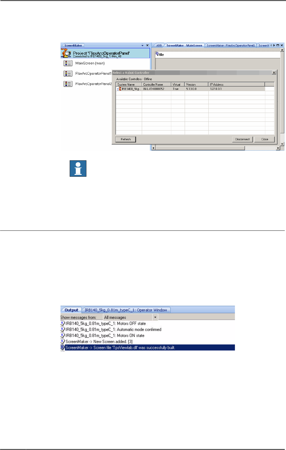
14 The ScreenMaker tab
14.2.2. Managing ScreenMaker projects
3HAC032104-001 Revision: D450
© Copyright 2008-2010 ABB. All rights reserved.
en0900000618
NOTE!
• To remove the connection with the controller, click Disconnect from the Project
context menu.
• To shift between Online and Offline modes, click Switch to Online Controller or
Switch to Offline Controller from the Project context menu.
Building a project
The result from building the ScreenMaker project is a set of files including DLL file and
images. The ScreenMaker project can be compiled into binary format (.dll) that can be
deployed on a FlexPendant.
Use this procedure to build a project:
1. Click Build from the ScreenMaker ribbon or right-click Project context menu and select
Build
The result is displayed in the output window.
en0900000404
Continued
Continues on next page

14 The ScreenMaker tab
14.2.2. Managing ScreenMaker projects
4513HAC032104-001 Revision: D
© Copyright 2008-2010 ABB. All rights reserved.
Deploying to controller
Use this procedure to deploy a ScreenMaker project to a real controller or virtual controller:
1. Connect to the controller you want to deploy to. See Connecting to controller on page
449.
2. Click Deploy from the ScreenMaker ribbon or right-click Project context menu and select
Deploy Screen to Controller.
The Download dialog box appears displaying the progress of download. It disappears
once the download is successful.
The TpsViewxxxxxx.dll file is downloaded.
3. Restart the controller.
NOTE!
• If a real controller is used, you can reboot the FlexPendant by moving its joystick three
times to the right, once to the left, and once towards you.
• If a virtual controller is used, you can reboot the FlexPendant by closing the virtual
FlexPendant window.
Continued

14 The ScreenMaker tab
14.2.3. Application variables
3HAC032104-001 Revision: D452
© Copyright 2008-2010 ABB. All rights reserved.
14.2.3. Application variables
Overview
Application variables, also called temporary variables are created for a ScreenMaker project.
During runtime, they reside in the FlexPendant memory. It is used for data sharing and
performance improvement. It is similar to a RAPID variable and has a RAPID data type.
Managing application variables
To create, delete, and rename an application variable, follow these steps:
1. In the Project context menu, right-click and select Application Variables. The Project
Application Variables dialog box appears.
2. Click Add and define the name, type and value of the new variable.
3. Select the variable, click Delete to delete a variable.
4. Select the variable, click Rename, enter the new name and click OK to rename a
variable.
5. Click Close.
en0900000402
NOTE!
For information on application variable data binding, see Application variable data binding
on page 463.

14 The ScreenMaker tab
14.2.4. Form designer
4533HAC032104-001 Revision: D
© Copyright 2008-2010 ABB. All rights reserved.
14.2.4. Form designer
Overview
The Form designer is a tool to edit or design a screen. It allows you to design the screen with
the required controls and the design area resembles a FlexPendant screen.
Editing a screen
To edit a screen, follow these steps:
1. Drag a control from the toolbox and drop it on the design area.
The Properties window displays all the properties of the control.
2. Select the control and resize or reposition for configuration.
NOTE!
You can either select a single control or multiple controls:
• Single control : Left-click the control on the design area or select the control from the
list in the Properties window.
• Multiple controls: Left-click on the design area, drag the mouse and create a window
selecting all the controls.
3. Click the smart tag on the upper right corner of the control to perform the basic tasks of
configuration. See Configuring data binding on page 459.
NOTE!
You can perform additional configuration by editing the attributes in the Properties
window. See Properties window on page 434.
Setup Events
Event handler is a set of actions to be executed after an event occurs.
To set up an event, follow these steps:
1. Select the control for which the event handler is to be defined.
2. Open the Events Panel dialog box in any one of the following ways:
• Double-click the control.
• Right-click the control, select Events Manager, click Add enter the name, and click
OK and close.
• Click smart tag and select the task from the list.
• In the Properties window, click Events icon and select the desired event from the list.
3. Click Add Action to add an action from a predefined list of actions.
Continues on next page

14 The ScreenMaker tab
14.2.4. Form designer
3HAC032104-001 Revision: D454
© Copyright 2008-2010 ABB. All rights reserved.
The following table lists the set of predefined actions:
Screens • Open Screen
• Close Screen
en0900000554
Signals • Set a Digital Signal
• Invert a Digital Signal
• Pulse a Digital Signal
• Read a Signal
• Write a Signal
• Reset a Digital Signal
en0900000555
RapidData • Read a Rapid Data
• Write a Rapid Data
en0900000553
Continued
Continues on next page

14 The ScreenMaker tab
14.2.4. Form designer
4553HAC032104-001 Revision: D
© Copyright 2008-2010 ABB. All rights reserved.
4. Select the action from the left window and perform the following:
• Click Delete to delete the action.
• Click Move Up or Move Down to change the order of execution of actions.
5. Click OK.
NOTE!
To delete a user created event handler, do the following:
1. Right-click the control, select Events Manager. The Events Manager dialog box
appears.
2. Select the event handler to be deleted from the list and click Delete.
Advanced • Call another Action list
• Call .NET method
• Call Custom Action
en0900000552
Continued
Continues on next page

14 The ScreenMaker tab
14.2.4. Form designer
3HAC032104-001 Revision: D456
© Copyright 2008-2010 ABB. All rights reserved.
Advanced options
Call another Action List
Existing event handlers from Events Manager can be reused by other controls while defining
actions for event. You can call another event handler from an existing event handler.
In the following example, listbox1_SelectedIndexChanged event handler is called from
comboBox1_SelectionIndexChanged event handler.
NOTE! Click Show warning message before performing actions checkbox to display a
message box before performing these actions.
en0900001046
Call .NET Method
You can import the dlls and add references to the Advanced tab of the Project Properties
dialog box.
en0900001047
Continued
Continues on next page

14 The ScreenMaker tab
14.2.4. Form designer
4573HAC032104-001 Revision: D
© Copyright 2008-2010 ABB. All rights reserved.
Once the references are defined, .NET methods appear in the Project Properties dialog box
and can be included in the Actions list which will be executed on performing the desired
action.
en0900001049
Double click the method and bind the return value to the application variable.
en0900001048
NOTE! Binding can be done only to the application variable. For more information, see
Application variable data binding on page 463.
Continued
Continues on next page

14 The ScreenMaker tab
14.2.4. Form designer
3HAC032104-001 Revision: D458
© Copyright 2008-2010 ABB. All rights reserved.
Call Custom Action
You can add an user control to the ScreenMaker toolbox and call a custom method for that
control by defining it in the ScreenMaker.dll.config file.
NOTE! Currently Call Custom Action only supports the Graph control.
In the following example, the Graph control has a method called UpdateValues that has to be
called when defining an action. You can view this information in the ScreenMaker by
defining it in the ScreenMaker.dll.config file.
en0900001045
Continued

14 The ScreenMaker tab
14.2.5. Data binding
4593HAC032104-001 Revision: D
© Copyright 2008-2010 ABB. All rights reserved.
14.2.5. Data binding
Overview
Data binding is the mechanism that links a GUI property with an external data source such
that whenever the data source is updated the GUI property will be updated automatically and
vice verse. Databinding has the following three aspects:
• A unidirectional connection means that an update of the data source is reflected by the
GUI, or vice versa; a bidirectional connection means that updates to either are
reflected by the other.
• A temporal connection can be suspended and resumed at any time.
• A convertable connection negotiates between the different data types or formats
between the data source and the GUI property.
A screen has to be linked with data to be useful. There are two ways of linking the data with
the GUI properties:
• Controller object data binding on page 462
• Application variable data binding on page 463
Configuring data binding
Data binding can be configured in the following two ways:
Using smart tag
Smart tags perform basic configuration tasks like binding default GUI property with
controller data. The controls that either display or edit information normally have a value
property to represent the information. Smart tag binds the value to the controller object.
• On the design area, select the control and click the smart tag. The tasks menu appears.
en0900000398
Using Binding menu
1. On the design area, select the control.
2. In the Properties window, locate the row from the table for binding the value.
3. Select the attribute and click the list to display the Binding menu.
Continues on next page

14 The ScreenMaker tab
14.2.5. Data binding
3HAC032104-001 Revision: D460
© Copyright 2008-2010 ABB. All rights reserved.
en0900000399
Configuring data binding for different controls
Almost all the controls defined in the toolbox (except ComboBox and ListBox) have the
following two options for binding values:
• Bind to a Controller Object
• Bind to an Application Variable
Binding to an array can be done with the following controls:
• DataEditor
• ComboBox
• ListBox
Menu Description
Remove actual binding Removes the existing data binding
Bind to a Controller object Select available data in the controller for binding.
Bind to an Application variable Select available data in project temporary data store for
binding.
Continued
Continues on next page

14 The ScreenMaker tab
14.2.5. Data binding
4613HAC032104-001 Revision: D
© Copyright 2008-2010 ABB. All rights reserved.
Control Description
DataEditor The default index value is 1. DataEditor is designed in such a way
that the default value of the Rapid array starts with 1 and not 0.
en0900000641
ComboBox and ListBox The default index value is -1. You can enter the appropriate index
value but cannot bind to a controller object or an application
variable.
en0900000642
NOTE!
• You can limit the number of items to be displayed in the
ComboBox and ListBox of an array.
• While using a ComboBox, a RAPID index starts with 1 (1
specifies the first element) and the ComboBox index starts
with 0( 0 specifies the first index).
Continued
Continues on next page

14 The ScreenMaker tab
14.2.5. Data binding
3HAC032104-001 Revision: D462
© Copyright 2008-2010 ABB. All rights reserved.
Controller object data binding
Controller object data binding lets you to select the data in the controller for binding.
Use this procedure to set up a binding with controller objects:
1. Select Bind to a Controller Object either using smart tag or binding menu.
The Controller Object Binding dialog box appears.
en0900000400
2. In the Type of object group, select either Rapid data or Signal data.
3. If you select Rapid data, from the Scope group, select a task and module from the list.
4. If you select Signal data, the Scope group is disabled.
5. In the See list, select the desired data.
Continued
Continues on next page

14 The ScreenMaker tab
14.2.5. Data binding
4633HAC032104-001 Revision: D
© Copyright 2008-2010 ABB. All rights reserved.
Application variable data binding
Application variables are used for data binding in the same way as controller data. See
Controller object data binding on page 462.
Use this procedure to set up a binding with application variables:
1. Select Bind to an Application Variable either using smart tag or binding menu.
The Application Variables Bind Form dialog box appears.
en0900000403
2. Select an application variable and the field to connect.
3. Click Setup Variables to manage the variables.
The Project Application Variables dialog box appears. See Managing application
variables on page 452.
4. Click OK.
Continued

14 The ScreenMaker tab
14.2.6. Screen navigation
3HAC032104-001 Revision: D464
© Copyright 2008-2010 ABB. All rights reserved.
14.2.6. Screen navigation
Overview
Screen navigation in ScreenMaker follows a tree structure.
Consider the following example,
• To open screen A1, you first have to open Screen A
• To navigate from screen A1 to screen B1, you first have to close screen A1 and then
Screen A and navigate from Main Screen through Screen B to screen B1.
• Similarly, to navigate from screen B1 to screen C1, you first have to close screen B1
and Screen B and then navigate from Main Screen through Screen C to screen C1.
en0900000645

14 The ScreenMaker tab
14.3.1. Overview
4653HAC032104-001 Revision: D
© Copyright 2008-2010 ABB. All rights reserved.
14.3 Tutorial
14.3.1. Overview
About this chapter
This chapter is designed as a tutorial to take you through the steps involved in designing a
FlexArc Operator Panel.
The FlexArc Operator Panel is a simple arc welding cell, where the robots can perform the
following three different jobs.
The FlexArc Operator Panel displays the following graphic elements:
• Controller Status (controller mode auto or manual and the RAPID execution status)
• Part Status (number of produced parts, the average cycle time per part, and a Reset
button)
• Robot jobs (Produce, Service, and Bull’s Eye) and Robot locations (Robot at home
position, service location, calibration location, and part location)
• Start and Stop buttons
en1000000359
Job Description
Produce Welding the part
Service Service the welding gun
Bull’s Eye Calibrate with bull’s eye

14 The ScreenMaker tab
14.3.2. Designing the FlexArc operator panel
3HAC032104-001 Revision: D466
© Copyright 2008-2010 ABB. All rights reserved.
14.3.2. Designing the FlexArc operator panel
Procedure
Use this procedure to design the FlexArc operator panel:
Action Info
1. Create a system for the FlexArc operator panel. For more information about creating a
system, see Creating a system from
layout on page 192.
NOTE! Ensure you select the
following options,
• FlexPendant Interface
• PC Interface
2. Load EIO.cfg and MainModule.mod files. For more information on loading these
files, see Loading a configuration file
on page 339 and Loading a RAPID
module on page 319.
By default,
•For Windows XP, the files can
be found at C:\Documents and
Settings\<user name>\My
Documents\RobotStudio\My
ScreenMaker Projects\Tutorial
•For Windows 7, the files can
be found at C:\Users\<user
name>\Documents\RobotStu-
dio\My ScreenMaker
Projects\Tutorial
3. The following signals are created after loading
EIO.cfg file
en1000000464
4. Create an empty station in RobotStudio with the
system created in the previous step.
For more information about creating a
station, see New Station on page 176.
5. Launch ScreenMaker from RobotStudio. For more information, seeLaunching
ScreenMaker on page 329.
Continues on next page

14 The ScreenMaker tab
14.3.2. Designing the FlexArc operator panel
4673HAC032104-001 Revision: D
© Copyright 2008-2010 ABB. All rights reserved.
6. Create a new ScreenMaker project. For more informaton, see Creating a
new project on page 443.
1. Enter the project name as
FlexArcGUI, and save it in the
default location,
C:\Users\<user name>\Docu-
ments\RobotStudio\My
ScreenMaker Projects\Tuto-
rial.
2. A new tab MainScreen is
added to the Design Surface.
7. Configure the Project properties. To customize how the GUI should
appear on the FlexPendant, modify
the Project properties. For more infor-
mation, see Modifying Project
properties on page 447.
8. Connect to the controller. For more information, see Connecting
to controller on page 449.
The result appears in the output
window.
9. Create application variables (temporary
variables) and configure them with the following
data
en1000000360
For more information, see Managing application
variables on page 452.
10. Design the Main Screen. For more information, see Designing
the screen on page 469.
11. Build and Deploy the project. For more information, see Building
and deploying the project on page
475.
Action Info
Continued
Continues on next page

14 The ScreenMaker tab
14.3.2. Designing the FlexArc operator panel
3HAC032104-001 Revision: D468
© Copyright 2008-2010 ABB. All rights reserved.
12. Open virtual FlexPendant and test the GUI • In RobotStudio, press Ctrl+F5
to launch the virtual Flex-
Pendant.
• Click FlexArc operator panel to
launch the GUI.
NOTE!
Ensure that you switch the controller
to Auto mode and start the RAPID
execution.
Action Info
Continued

14 The ScreenMaker tab
14.3.3. Designing the screen
4693HAC032104-001 Revision: D
© Copyright 2008-2010 ABB. All rights reserved.
14.3.3. Designing the screen
Introduction to designing the screen
A major effort in the GUI project development is designing screens. The Form designer in the
ScreenMaker allows you to drag controls from the toolbox to the design surface. Using the
Properties window, you can resize, position, label, color, and configure the controls.
Designing FlexArc Operator Panel screen
Use this procedure to design the FlexArc Operator Panel screen:
1. Drag a GroupBox control from the General category; place it on the design surface and
set the following values in the Properties window.
2. Drag another GroupBox control from the General category; place it on the design surface
and set the following values in the Properties window.
3. Drag a ControllerModeStatus control from the Controller Data category; place it in the
Controller Status groupbox created and set the following values in the Properties window:
4. Drag a RapidExecutionStatus control from the ControllerData category; place it in the
Controller Status groupbox created and set the following values in the Properties window:
Property Value
Location 14,45
Size 150,100
Title Controller Status
BackColor LightGray
Property Value
Location 14,170
Size 150,204
Title Part Status
BackColor LightGray
Property Value
Location 19,40
Size 44,44
BackColor LightGray
Property Value
Location 80,40
Size 44,44
BackColor LightGray
Continues on next page

14 The ScreenMaker tab
14.3.3. Designing the screen
3HAC032104-001 Revision: D470
© Copyright 2008-2010 ABB. All rights reserved.
5. Drag a TpsLabel control from the General category; place it in the Part Status groupbox
created and set the following values in the Properties window:
6. Drag a NumEditor control from the ControllerData category; place it in the Parts Status
groupbox created and set the following values in the Properties window:
7. Drag another TpsLabel control from the General category; place it in the Part Status
groupbox created and set the following values in the Properties window:
Property Value
Location 16,30
Size 131,20
Text Parts Produced
BackColor LightGray
Font TpsFont10
Property Value
Location 16,56
Size 116,23
Value Link to RAPID variable partsReady defined in the module
MainModule.
en1000000373
Property Value
Location 16,89
Size 131,20
Text Cycle time/part
BackColor LightGray
Font TpsFont10
Continued
Continues on next page

14 The ScreenMaker tab
14.3.3. Designing the screen
4713HAC032104-001 Revision: D
© Copyright 2008-2010 ABB. All rights reserved.
8. Drag another NumEditor control from the General category; place it in the Part Status
groupbox created and set the following values in the Properties window:
9. Drag a Button control from the General category; place it in the Part Status group box
created and set the following values in the Properties window:
Perform the following for the Reset button in the Part Status group:
Property Value
Location 16,115
Size 116,23
Value Link to RAPID variable cycleTime defined in the module
MainModule.
Property Value
Location 33,154
Size 85,34
Tex t Reset
Step Action
1 Double-click the button Reset. The Events Panel dialog box appears which is used
to define the actions for Events.
2 In the Events Panel dialog box, click Add Action; point to Rapid Data and select
Write a Rapid Data.
The Action Parameters dialog box appears; assign Rapid data to the following value
and click OK.
• T_ROB1.MainModule.partsReady to MyResetValue.Value
en1000000387
Similarly, assign Rapid data to the following value and click OK.
• T_ROB1.MainModule.cycleTime to MyResetValue.Value
NOTE! Two actions of similar type are needed to perform the Reset action. One is to
reset Rapid variable partsReady to 0, the other is to reset Rapid variable cycleTime
to 0.
Continued
Continues on next page

14 The ScreenMaker tab
14.3.3. Designing the screen
3HAC032104-001 Revision: D472
© Copyright 2008-2010 ABB. All rights reserved.
10.Drag a PictureBox control from the General category; place it on the design surface and
set the following values in the Properties window:
NOTE!
You can find the graphic (.GIF ) files at C:\MyDocuments\RobotStudio\My ScreenMaker
Projects\Tutorial\Images.
11. Drag another PictureBox control from the General category; place it on the design surface
and set the following values in the Properties window:
NOTE! Add AllowMultipleStates option to the PictureBox control. The objective is to
have an image that changes when an I/O signal changes.
For more information on how to use AllowMultipleStates for PictureBox control, see
Picture object and changing images due to I/O on page 477.
12.Drag a Button control from the General category; place it on the design surface and set
the following values in the Properties window:
Property Value
Location 177,28
Size 284,359
SizeMode StretchImage
Image FlexArcCell.GIF
Property Value
Location 237,31
Size 48,48
SizeMode StretchImage
Image RobotAtHome.GIF
AllowMultipleStates True
NOTE! Select Image property from the StatesEditor dialog box
SlectedStateValue DI_RobotAtHome
States Link State{0} to RobotAtHome_gray.GIF
Link State{1} to RobotAtHome.GIF
Property Value
Location 486,66
Size 116,105
Text Start
Font TpsFont20b
BackColor LimeGreen
Enabled Link to DI_RobotAtHome
Continued
Continues on next page

14 The ScreenMaker tab
14.3.3. Designing the screen
4733HAC032104-001 Revision: D
© Copyright 2008-2010 ABB. All rights reserved.
Perform the following for the Start button:
13.Drag a Button control from the General category; place it on the design surface and set
the following values in the Properties window:
Perform the following for the Stop button:
14.Drag a Button control from the General category; place it on the design surface and set
the following values in the Properties window:
Step Action
1 Double-click the button Start or click the Smart tag and select Define Actions when
clicked. The Events Panel dialog box appears which is used to define the actions
for Events.
2 In the Events Panel dialog box, click Add Action; point to Rapid Data and select
Write a Rapid Data. The Action Parameters dialog box appears.
3 In the Action Parameters dialog box, assign Rapid data to the following value and
click OK.
• T_ROB1.MainModule.JobProduce to JobProduce
Property Value
Location 486,226
Size 116,105
Tex t Stop
Font TpsFont20b
BackColor LimeGreen
Enabled Link to DI_PRODUCE
Step Action
1 Double-click the button Stop or click the Smart tag and select Define Actions when
clicked. The Events Panel dialog box appears which is used to define the actions
for Events.
2 In the Events Panel dialog box, click Add Action; point to Rapid Data and select
Write a Rapid Data. The Action Parameters dialog box appears.
3 In the Action Parameters dialog box, assign Rapid data to the following value and
click OK.
• T_ROB1.MainModule.JobIdle to JobIdle
Property Value
Location 274,246
Size 111,47
Tex t Bull’s Eye
Font TpsFont14b
Enabled Link to DI_RobotAtHome
AllowMultipleStates True
NOTE! Select BackColor property from the StatesEditor
dialog box
SelectedStates DI_RobotAtBull'sEye
States Link State{0} to Red
Link State{1} to Green
Continued
Continues on next page

14 The ScreenMaker tab
14.3.3. Designing the screen
3HAC032104-001 Revision: D474
© Copyright 2008-2010 ABB. All rights reserved.
Perform the following for the Bull’s Eye button:
15.Drag a Button control from the General category; place it on the design surface and set
the following values in the Properties window:
Perform the following for the Service button:
Step Action
1 Double-click the button Bull’s Eye or click the Smart tag and select Define Actions
when clicked. The Events Panel dialog box appears which is used to define the
actions for Events.
2 In the Events Panel dialog box, click Add Action; point to Rapid Data and select
Write a Rapid Data. The Action Parameters dialog box appears.
3 In the Action Parameters dialog box, assign Rapid data to the following value and
click OK.
• T_ROB1.MainModule.JobBulls to JobBulls
Property Value
Location 274,324
Size 111,47
Text Service
Font TpsFont14b
Enabled Link to DI_RobotAtHome
AllowMultipleStates True
NOTE! Select BackColor property from the StatesEditor
dialog box
SelectedStates DI_RobotAtService
States Link State{0} to Red
Link State{1} to Green
Step Action
1 Double-click the button Service or click the Smart tag and select Define Actions
when clicked. The Events Panel dialog box appears which is used to define the
actions for Events.
2 In the Events Panel dialog box, click Add Action; point to Rapid Data and select
Write a Rapid Data. The Action Parameters dialog box appears.
3 In the Action Parameters dialog box, assign Rapid data to the following value and
click OK.
• T_ROB1.MainModule.JobService to JobService
Continued

14 The ScreenMaker tab
14.3.4. Building and deploying the project
4753HAC032104-001 Revision: D
© Copyright 2008-2010 ABB. All rights reserved.
14.3.4. Building and deploying the project
Procedure
1. From the ScreenMaker ribbon, click Build.
For more information on building the project, see Building a project on page 450.
2. From the ScreenMaker ribbon, click Deploy.
For more information on deploying the project, see Deploying to controller on page 451.
3. In RobotStudio, press Ctrl+F5 to launch the Virtual Flexpendant and click FlexArc
Operator Panel to open the GUI.
NOTE!
Ensure that you start the RAPID execution and switch the controller into Auto mode.

14 The ScreenMaker tab
14.4. Frequently asked questions
3HAC032104-001 Revision: D476
© Copyright 2008-2010 ABB. All rights reserved.
14.4. Frequently asked questions
How to deploy manually to a Virtual Controller
If for any reason you wish to manually by-pass the Deploy button in RobotStudio and the
virtual controller, the following information describes what files are to be moved.
Actions
Location of output files
The files that contain the FlexPendant application from ScreenMaker are found (for example)
in the bin directory under the My ScreenMaker Projects located in the My documents
directory of the user.
For example, My Documents\My ScreenMaker Projects\SCM_Example\bin where
SCM_Example is the example ScreenMaker project.
The files in the bin directory are to be copied to a location where the Virtual FlexPendant can
read them during the start of the FlexPendant.
Location where the Virtual FlexPendant reads the files
The recommended location for manually copying the ScreenMaker output files is the location
of the virtual controller system.
If the system is created manually from System Builder, it is located in the My Documents
directory.
For example, My Documents\IRB4400_60_SCM_Example\HOME where
IRB4400_60_SCM_Example is the example controller system.
If the system is created by a Pack-and-Go and then restored, it is located in the
RobotStudio\Systems folder.
For example,
MyDocuments\RobotStudio\Systems\IRB4400_60_SCM_Example\HOME where
IRB4400_60_SCM_Example is the example controller system.
Copy files
Copy the files from the ScreenMaker output to the Home directory of the virtual controller
system.
Restart the Virtual FlexPendant and the new application will be loaded.
Continues on next page

14 The ScreenMaker tab
14.4. Frequently asked questions
4773HAC032104-001 Revision: D
© Copyright 2008-2010 ABB. All rights reserved.
Picture object and changing images due to I/O
The typical user objective is to have an image that changes when an I/O signal changes, this
is common for a digital input to affect the state on the FlexPendant.
Actions
This is accomplished by adding an image and allowing the image to have multiple states.
Set AllowMultipleState to TRUE and set the Image state.
en0900000668
Create two states and add images for each state:
en0900000669
Continued
Continues on next page

14 The ScreenMaker tab
14.4. Frequently asked questions
3HAC032104-001 Revision: D478
© Copyright 2008-2010 ABB. All rights reserved.
The Value property is extremely important. If binding to a digital input then there are two
states for the input, 0 and 1. Set the Value property to the value of the bound variable. 0 and
1 for digital input. It is also possible to bind to RAPID variables and have multiple states and
values for the values in the RAPID variable.
Set the SelectedStateValue property to bind to a controller object:
en0900000670
Using CommandBar and the menu items
Using CommandBar allows button to appear at the bottom of the screen in a controlled and
organized order.
en0900000671
In the preceding graphic, the CommandBar has three menu items Gate, Conveyor, and
Motor. The objective is to have events trigger when these are clicked.
Continued
Continues on next page

14 The ScreenMaker tab
14.4. Frequently asked questions
4793HAC032104-001 Revision: D
© Copyright 2008-2010 ABB. All rights reserved.
Actions
First create the CommandBar and add the menu items (either by editing the menu items
property or by clicking the small arrow on the upper right of the active CommandBar) and
add the menu items.
en0900000672
To add events to the menu items, go to the Properties dialog and select the menu item from
the drop down list.
en0900000673
Continued
Continues on next page
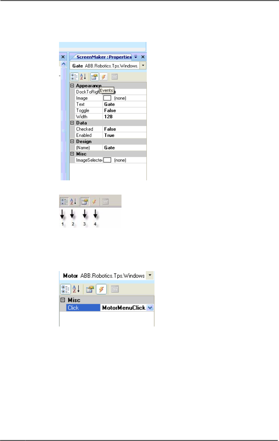
14 The ScreenMaker tab
14.4. Frequently asked questions
3HAC032104-001 Revision: D480
© Copyright 2008-2010 ABB. All rights reserved.
Select Gate menu item. The following dialog appears.
en0900000674
en0900000409
1. In the preceding graphic, select 4 to add an event when the menu item is clicked.
2. Click the drop-down list to select the event. The events are added automatically
For more information on various ways of opening the Events Panel dialog box, see Setup
Events on page 453.
en0900000675
Continued
Continues on next page

14 The ScreenMaker tab
14.4. Frequently asked questions
4813HAC032104-001 Revision: D
© Copyright 2008-2010 ABB. All rights reserved.
en0900000676
When adding CommandBar menu items, ensure that the Text property is filled. If not, nothing
appears on the CommandBar.
en0900000677
Continued
Continues on next page

14 The ScreenMaker tab
14.4. Frequently asked questions
3HAC032104-001 Revision: D482
© Copyright 2008-2010 ABB. All rights reserved.
How to get radio buttons to show state when entering
The objective is to have two radio buttons that controls one digital output. When the screen
is loaded, the buttons should show the current state of the output.
Actions
Create a group or a panel and place the two radio buttons on the group or panel.
For button1, set the property default value to True and bind the property to the value of the
controller digital output signal.
For button2, do not do any changes.
When the screen is loaded, the state of the two radio buttons is established correctly.
Continued

Index
4833HAC032104-001 Revision: D
© Copyright 2008-2010 ABB. All rights reserved.
A
ABB library 190
action instruction
about
21
Activate RobotStudio
Manual activation 32
Add Controller
342
add to path 375
alerts
activate
132
align frame orientation 376
align target orientation 377
Application grants
362
Application Variables 452
create,delete, rename application variables
452
FlexPendant memory
452
RAPID variable
452
attach to object
378
Authenticate
345
Edit User Accounts
345
Log in as Default User
345
Log off 345
Log off all controllers 345
Login as a Different User
345
UAS Grant Viewer 345
auto configuration 379
B
Back up
restore backup 332
Backup
331
create backup 331
base coordinate system 22
browser
Layout
35
Modeling 38
Paths & Targets
36
C
CAD file
troubleshoot and optimize
78
CAD formats
convert 77
check reachability
380
collision
detection 127
sets
127
configuration
robot axis 24
configuration editor
334
instance editor 338
configuration file 169
configuration monitoring
about
25
Configure data binding 459
Using Binding menu
459
Using Smart tag 459
confJ
about
25
ConfL
about
25
Connecting a controller 449
control panel
367
enable device 367
manual full speed 367
motors on
367
operation mode 367
release device 367
reset emergency stop
367
Controller grants 360
Backup and save 360
Calibration
361
Delete log 361
Edit RAPID code
360
Execute program
360
Full access
360
I/O write access
360
Manage UAS settings
360
Modify configuration
360
Modify controller properties
361
Modify current value
360
Program debug
361
Read access to controller disks
361
Safety Controller 361
Write access to controller disks 361
controller menu
169
Controller Shutdown 368
Terminate Virtual Controllers 368
controller system
create
145
controller tab 43
access
44
controller name 43
controller state 43
logged on as
44
operating mode 43
program execution state 43
system name
43
controller world coordinate system
22
convert frame to workobject
382
coordinate systems
22
cycle tme
measure 133
D
Data Binding 459
Application variable data binding 463
Controller object data binding
462
data declaration 19
detach 385
detecting collision
128
Development Environment 430
device browser 351
E
editor 121
element
select
55
Ethernet 140
event
create
130

Index
484 3HAC032104-001 Revision: D
© Copyright 2008-2010 ABB. All rights reserved.
events 314
event log 314
external axis
program
117
F
File transfer 346
Controller explorer 347
PC explorer 347
FlexPendant Viewer
348
Frame
create 196
create from three points
197
frame
converting to workobject
92
crerating by points
92
frames
22
function
19
G
geometry
troubleshoot and optimize
78
Getting started window 34
Go Offline 353
Grants, about
144
Grants, give to groups 358
graphics window 54
Group, about
143
group, add 357
group, add user 356
group, remove
358
group, rename 357
Groups, give grants 358
H
handle events 171
date and time 172
event category
172
event code
172
event description
172
event log list
171
event title
172
event type
171
manage events
173
retrieve controller events
173
sequential number
172
I
I/O
set 131
I/O system
326
I/O signals 165
input signals 165
output signals
165
simulated signals 165
virtual signals 165
import
75
Import geometry 195
import library
191
instruction 19
about 21
item
select
55
J
jog
mechanism 93
robot
93
several mechanisms 93
jointtarget
creating
94
K
keyboard shortcuts 57
General commands
57
Program Editor commands 57
Program Editor hotkeys
58
Program Editor Intellisense
57
L
Layout browser 35
LED
433
library
troubleshoot and optimize
78
load module 319
Load Parameters 339
local coordinate system
set
84
local origin
set
84
M
Manage ScreenMaker Project 442
Close project
445
Create project 443
Load project 444
Save project
445
Manage ScreenMaker project
Close ScreenMaker 445
Manage Screens
445
Create screen
445
Delete screen
446
Edit screen
446
Rename screen
446
Managing ScreenMaker Projects
Build project
450
MediaPool 18
Mirror 398
Modeling browser
38
Modify project properties 447
module 19
Move instruction
teach
219
move instruction
about
21
MoveJ
teach 219
MoveL
teach
219
MultiMove
programming workflow
110

Index
4853HAC032104-001 Revision: D
© Copyright 2008-2010 ABB. All rights reserved.
N
near-miss detection 128
network settings 141
firewall settings
141
local network connection 141
remote network connection 141
service port connection
141
new module 318
NONSTEPIN 318
READONLY
318
VIEWONLY 318
O
object
select
55
set local origin
84
troubleshoot and optimize
78
Offline and Online browser
39
operator window
45
enabling operator window
45
show virtual operator window
45
orientations
99
align target 100
copy and apply 101
target normal to surface
99
unordered 99
output window 42
event types
42
P
pack, unpack 136
part
set local origin
84
Password, change for user 356
path
96
about 21
compensating 97
creating
96
creating from curve
96
reversing
96
rotating
97
setting axis configuration
96
translating
97
Paths & Targets browser
36
Placing an item 411
Frame 411
One Point
411
Three Points 411
Two Frames 411
Two Points
411
positioner.program 117
procedure 19
process time
measure
133
program 121
copy
135
programming
overview
91
Properties 350
Device Browser 351
Renaming the controller
350
Set controller ID 351
Set date and time
350
View controller and system properties 351
Properties Window
Event Help panel
434
Graphical Component Name panel 434
Properties window toolbar 434
Table panel
434
Property editor 265
R
RAPID
concepts 19
copy program
135
RAPID editor
316
RAPID instructions
102
RAPID task
323
task window
323
RAPID Watch Online
174
reachability
test
108
Release Write Access 344
remote subnet
142
Request Write Access 343
robot
programming overview
91
Robot system button 192
adding a template system 193
adding an existing system
193
conveyor setup 194
create system from layout 192
remove objects from conveyor
194
RobotWare 17
license key 17
RobotWare system
17
routine
19
Run mode
366
continuous
366
single
366
S
safety 14
safety configuration
341
Screen navigation
464
service port
139
set task frame
369
signals
set
131
simulate
alerts 132
create event
130
measure process time 133
set signals 131
TCP trace
132
simulation 125, 127
Simulation watch 266
Break condition
267
station
build workflow
61
pan 54

Index
486 3HAC032104-001 Revision: D
© Copyright 2008-2010 ABB. All rights reserved.
rotate 54
zoom 54
station world coordiante system
22
switch 433
synchronization 120
station to VC
120
VC to station 120
system
create
145
create with positioner 162
RobotWare 17
System Builder
145, 333
about virtual and real systems 145
building new system
148
copying system
156
create boot media
159
create system from backup
157
download a system to controller
158
modify controller system
152
viewing system properties
147
System Configuration
370
controller values
371
stored station values
371
used current station values 371
system parameters 166
editing parameters
167
load parameters 170
save system parameters 169
T
target 94
about 21
creating
94
modifying 94
modifying with ModPos 94
removing unused
95
renaming
95
teaching
94
Targets on Edge
205
TCP
22
TCP trace
activate
132
Tool Center Point coordinate system
22
ToolBox
ActionTrigger
433
BarGraph
433
CheckBox 433
ComboBox
433
CommandBar 433
ControllerModeStatus 433
DataEditor
433
Graph 433
GroupBox 433
ListBox
433
NumEditor 433
NumericUpDown 433
Panel
433
PictureBox 433
RapidExecutionStatus
433
RunRoutineButton 433
TabControl
433
tooldata 83
tools
83
TpsLabel 433
track
program
117
trap 19
U
UAS Grant Viewer 359
UCS 23
unpack 179
User account
354
User tab 354
user coordinate system
23
User, about
143
User, add
355
User, add to group
356
User, change password
356
User, change user name
356
User, enable and disable
356
User, remove 355
V
viewpoint 230
create 230
move to viewpoint 231
viewpoint functions
230
Virtual FlexPendant 365
Virtual FlexPendant operator window 45
VSTA
29
W
WorkObject 23
workobject
creating
92
modifying 92
workobjects
92
world coordinate system
22

3HAC032104-001 Rev D, en
Contact us
ABB AB
Discrete Automation and Motion
Robotics
S-721 68 VÄSTERÅS
SWEDEN
Telephone +46 (0) 21 344 400
www.abb.com
