
TOOLS NEEDEDITEMS INCLUDED
Front and Rear lights
Wiring harness
Rocker switch
Turn Signal
Brake Switch
Horn
USB port
Converter
Column Cover
RGB Module (02-104)
Phillips Head Screw
Driver
Cutting Tool
Sandpaper
Power Drill
Flat Head Screwdriver
8mm Socket
V:D
Will fit Yamaha® Drive2®
LED ULTIMATE LIGHT KIT PLUS #02-058
LED LUX LIGHT KIT #02-104
Installation Instructions for:
Control box features:
• 30 second turn signal timer
• Eliminates flashers/ Relay
• Brake Lights Automatically
turn off after 3 minutes of
setting parking brake.
RGB Module controlled by
Happy Light App

*ATTENTION: The Instructions for this Ultimate Plus Light Kit & LED LUX Light Kit are identical*
STEP 1
STEP 2
Switch key to OFF position. Place TOW/RUN switch to TOW. It is not required to remove the batteries but you
do need to disconnect the main negative.
Remove all plastic rivets from oor mat. Retain
hardware. Remove oor mat.
Lift plate from oor to expose pedal assembly.
Brake Switch
Harness
Converter
USB
Headlights
Tail Lights
Straps
Push Nuts
Optional RGB Module
for 02-104
Control Box
Module
We recommend professional installation. If you choose to not have this product installed by a professional,
we highly recommend that you exercise caution, care, and patience when installing this product.
Ultimate PlusUltimate Plus
HarnessHarness
Ultimate PlusUltimate Plus
HarnessHarness
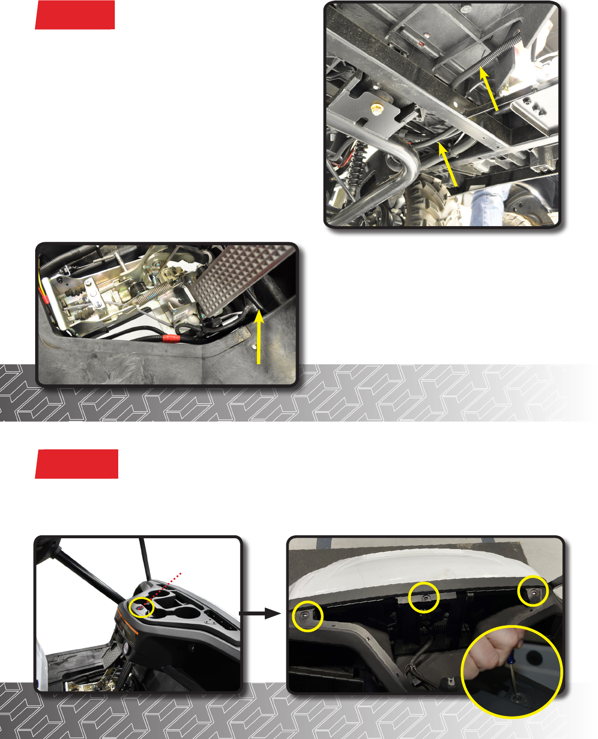
MAIN HARNESS
From the battery compartment, route wiring harness
behind the battery pack forward along the brake cables
to the brake pedal assembly. Pull headlight wiring from
pedal assembly to front of cart. Route wiring harness
through dash to mount hazard rocker switch and USB
port. Route tail light wiring to the rear of the cart. Loosely
secure with wire ties until all lights have been installed.
IMPORTANT: Route wiring harness in such a way to
prevent it rubbing against or being pinched by moving
parts, such as the suspension.
Red plugs should be aligned to passenger side,
white plugs for driver’s side.
STEP 3
STEP 4A
A
Remove
Yamaha
®
Emblem
and set screw
A) Remove Yamaha
®
Emblem and set screw, then remove cup holder insert and save hardware for later. With
the cup holder detached remove the three push rivets in the console.
*Note use a small screw driver to push center in to release rivet*
*COWL REMOVAL

B) There is one push rivet located in each Front
Fender Well. They will need to be removed as well.
B
STEP 4B
STEP 4C
C1
C2
C1) Remove the nal 6mm screw holding the cowl on
and then (C2) unplug both Headlights. Keep track of
all removed hardware, you will need it later.
To remove Factory cowl, use small screw driver to press in and release clips.
STEP 5

STEP 7
STEP 6
Place the cowl on a at surface and use something to
prevent scratching. Then remove factory Headlight
push nuts, by gently prying them o with needle
nose pliers to avoid damage.
Remove Headlight.
Align headlight template to the body contour as shown. Be
sure to use alignment references for proper placement. Use a
marking pen to trace the inside line.
Next drill a pilot hole so you will have a starting point and then
begin cutting. Be sure to drill and make cuts to the inside of
the line.
*Use sandpaper to smooth edge.
*Flip template over and repeat process on other side.
*For carts without a pre-cut hole:
STEP 8
Mount headlight through the cutout using
supplied push nuts.
*Repeat process on opposite side.
(3) 7.5mm Push Nuts

STEP A
STEP B
STEP C
ATTENTION: For Ultimate Plus Light Kit Instructions (02-058), Skip to Step 10.
To access the features of your RGB Module download the Happy Light App and follow the provided instructions.
Plug 3 Pin Connector from RGB Module to 3-Pin on
Headlight.
Connect the 4-Pin connector from Main Harness to
4-Pin Connector on Headlight.
At the front of the car connect the 2-Pin connector
from RGB Module to the Main Harness.
OPTIONAL RGB MODULE INSTALL FOR 02-104 DRIVE
2
LUX LIGHT KIT
Optional RGB Module
for 02-104
STEP 9
Plug in 6 pin connector from headlight to 6 pin
on harness.
NOTE: Red connector for Passenger side
OPTIONAL RGB MODULE INSTALL COMPLETE

*For carts without a pre-cut hole:
Align Tail Light template to the body contour as shown. Be
sure to use alignment references for proper placement.
Use a marking pen to trace the inside line.
Next drill a pilot hole so you will have a starting point and
then begin cutting. Be sure to drill and make cuts to the
inside of the line.
*Use sandpaper to smooth edge.
*Flip template over and repeat process on other side.
*For carts with factory lights:
Remove factory tail light hardware. To make tail light
removal easier, remove the 5 rivets from inner fender
well and retain all.
Disconnect factory tail light wiring harness from tail
light.
STEP 11
STEP 10
*Tail Light Install*
A
(3) 7.5mm Push Nuts
Mount tail light through the cutout using
supplied push nuts.
*Repeat process on opposite side.
STEP 12

Find a desired location on your dash to mount
the hazard switch. Ensure the location is free of
obstacles and will not aect dash reattachment.
Using a 15/32” bit, drill a mounting hole and
insert switch into dash. Secure with the ring nut
from back of switch.
Reattach wires: Black behind led, Blue on
center post, and Yellow on top post.
Feed the tail light harness through the back of
the cart. Attach rear tail light wire harness as
shown. Secure wire with ties.
Route 12 pin of main harness towards cupholder.
Connect 12 pin of turn signal module to main
harness. Secure module in dash panel under
cup holder.
STEP 13
STEP 14
STEP 15
*Hazard Switch Install*

Using a 1 1/8” paddle bit, nd a desired location on
your golf cart dashboard to mount your USB charger.
Ensure your location is free of obstacles and will not
aect dash reattachment.
17A) Remove the 1 bolt shown under the brake
cable at the rear of the pedal assembly. Align the
brake switch bracket over the bolt hole, replace and
tighten the bolt. Install the switch in the bracket with
the spring toward the front of the cart.
17B) Pedal assembly has a hole to the left of the
brake cable using a #6 Bolt Nut & Lock washer
secure to assembly. Make sure spring faces forward.
Remove the pin that attaches the brake cable clevis
to the pedal. Replace the pin with the longer pin
provided in the brake switch kit. Use the provided
clip to hold the pin in place. Loop hook on spring
over the pin making sure the spring is seated in the
groove of the pin.
Adjust the brake switch so that the spring has no
slack but the switch is not engaged.
Plug the 2 bullet connectors on the switch into the
corresponding bullet connectors on the light kit
harness.
STEP 16
STEP 17
*USB Charger Install*
*Brake Switch Install*
Using the supplied ring nut, mount the charger in the
to your cart.
Plug the red and black 12 volt accessory connection
from the light kit harness to the spade terminals on the
back of the charger, red to (+) and black to (-).
Note: Two Options To Mount Brake Switch. Follow Directions For Procedure That Best Fits Your Cart.
*Shown o cart for instructional purposes only*
B
A
Mount indicator assembly using clamps provided
and tighten. Run indicator harness along steering
column and insert harness through dash.
Attach turn signal back cover to turn signal assembly.
Attach column cover to steering column, secure
harness in column cover void.
Plug in the 12 pin connector.
Reinstall dashboard using retained hardware.
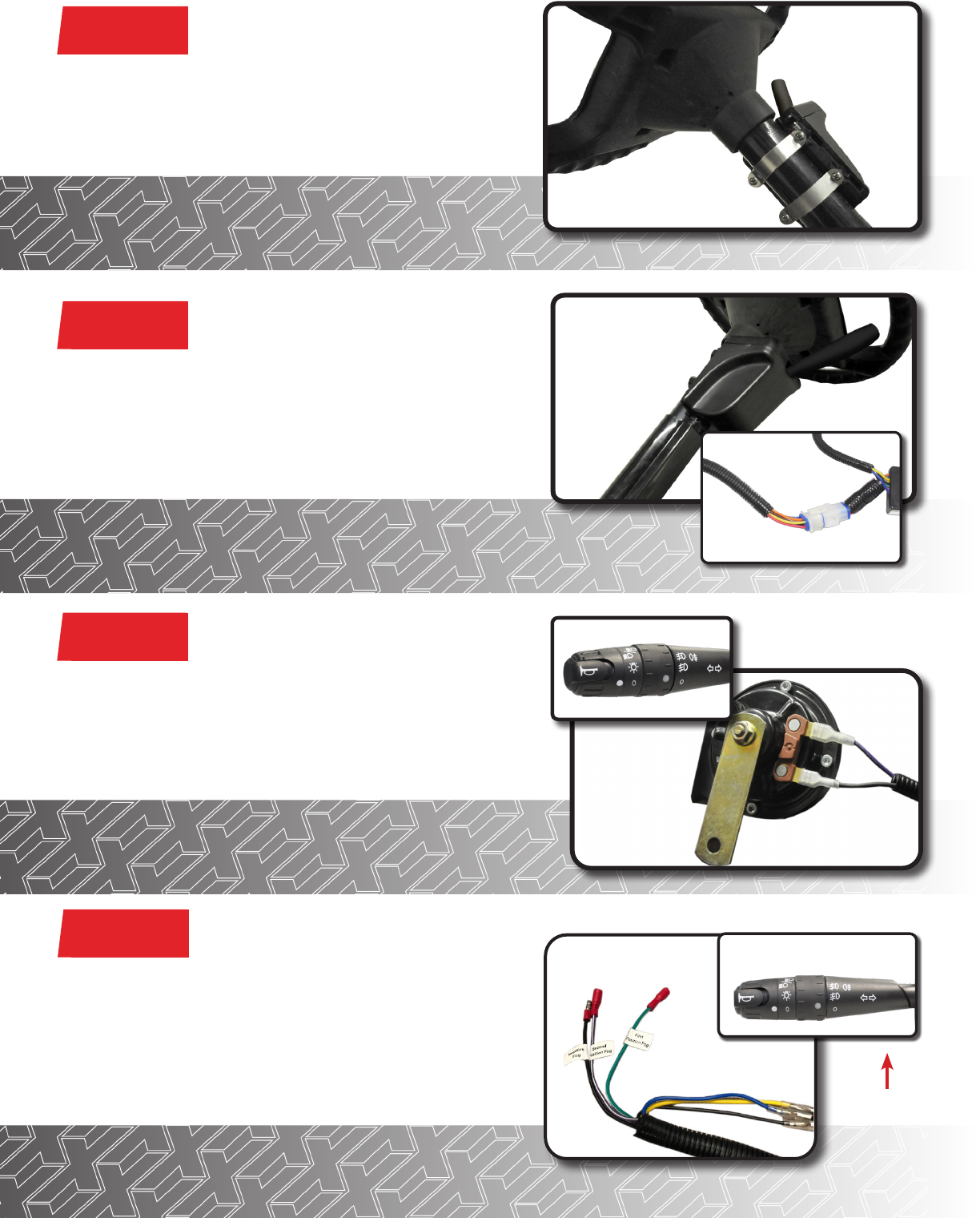
STEP 18
STEP 19
STEP 20
Attach horn to purple and black female spade connectors
from front of harness and secure horn to metal framework
under front cowl with a self tapping screw.
Note: Horn is operated at the Turn Assembly.
*Wires have no orientation and will work on either post.
*Turn Signal Install*
The turn signal handle has a secondary, 2-position rotary
switch for auxiliary 12 volt lighting such as fog lights and/or
LED light bars. There is one common negative wire and two
positive wire connections to run two dierent auxiliary lights.
Additional wiring and lighting not included.
Reinstall cupholder using retained hardware from Step 4.
Auxiliary rotary
switch
STEP 21
*Auxiliary Switch Feature*

STEP 22
*Converter Install*
The voltage converter included must be used on all carts electric and gas. Connect the red wire with the fuse to
the MAIN positive terminal of the battery pack. Connect the black wire to the MAIN negative terminal of the battery
pack and tighten hardware.
Mount the converter to a at surface under the seat. (Metal area is preferred). Plug the connector with the yellow
and black wire into the light kit harness (you will notice a small arc when connecting). Reconnect battery and place
run/tow switch to run.
*Use converter on gas carts to prevent Starter Generator voltage spikes that could cause
damage to accessories.
Plugs into Light Kit Harness
To Main (+)
To Main (-)
INSTALLATION COMPLETE
E-Z-GO
®
, TXT
®
, RXV
®
and S4
®
are registered trademarks of Textron Innovations, Inc. Club Car
®
, Precedent
®
, DS
®
, Onward
®
and Tempo
®
are registered trademarks of Ingersoll
Rand, Inc. Yamaha
®
, Yamaha
®
Drive
®
, Drive2
®
,
G-14
®
, G-16
®
, G-19
®
, G-22
®
and G-29
®
are registered trademarks of Yamaha Golf-Car Company. Any reference to Club Car
®
, E-Z-
GO
®
, or Yamaha
®
or their associated trademarks, word marks, and products are only for purposes of identifying golf carts with which this Madjax product is compatible. Madjax
products are aftermarket parts and are not original equipment parts. Madjax is not connected to, aliated with, sponsored by, or endorsed by either Textron Innovations, Inc.,
Ingersoll Rand, Inc., Yamaha Golf Cart Company, or any of their parent or subsidiary companies.
Main (+)
Main (-)
