
Alpha Bucket Harness
(Optional for Taillights 02-040-TL)
Alpha Front Harness
Off-Road
Grill
OR
Headlights
Cowl
Front Cowl Braket
Frame Extenders
Hardware Packs
Street Grill
Hood Scoop
(Sold Seperately)
Red: 05-041
White: 05-044
Blue: 05-042
Black: 05-043
Red: 05-036
White: 05-037
Blue: 05-038
Black: 05-039
(05-021)
(05-063)
(05-057)
ALPHA CUSTOM BODY INCLUDES
Light Mounting Brackets
Light Mounting
Brackets
Alpha Bucket
Harness
Alpha Front
Harness
TOOLS NEEDED
Module
for 02-107
Converter
Brake
Switch
USB Port
LUX Control Box Module
LUX Module
controlled by
Happy Light App
LED Light Kit
ITEMS INCLUDED TOOLS NEEDED
• Headlights
• Tail Lights
• Light Mounting Brackets
• Alpha Bucket Harness
• Turn Signal Assembly
• Column Cover
• #2 Phillips Tip
• 1-1/8” Paddle Bit
• Torx Bit Socket Set
• 1/2” Wrench
• 13mm Socket
• Rotary Cutting Tool
• Hardware Pack
• 48-12V Converter
• Horn
• Brake Switch
• USB Charger
• Module (02-107 only)
(will fit Alpha Body/Club Car® Precedent & Tempo)
Part # 02-107 Alpha Kit
02-130 Alpha Ultimate Plus
Headlights
Turn Signal Assembly
w/Control Box
Column Cover
Taillights
Horn

STEP 2
Remove all screws securing floor mat to the vehicle
using a T40 Torx Bit. Remove floor mat & retain
hardware.
Remove the brake adjustment access panel for Brake
switch installation later.
Switch key to OFF position. Place TOW/RUN switch to
TOW. It is not required to remove the batteries but you
do need to disconnect the main negative.
STEP 1
*ATTENTION: The Instructions for the Ultimate Plus & LED LUX Light Kits are identical and should be
installed in conjunction with the Alpha Body kit instructions to avoid repeating steps.
Madjax recommends professional installation. If you choose to not have this product installed by a
professional, we highly recommend that you exercise caution, care, and patience when installing
this product as it involves drilling holes into your cart’s body.
WARNING:
Access Panel

STEP 4
Using a small screwdriver, pry charge receptacle cover
from vehicle.
Temporarily remove factory body screws using a T27
Torx Bit.
STEP 3
STEP 5
Remove the screws securing the lower body trim to the
body using a T40 Torx Bit. Remove the lower body trim
and retain hardware.
Starting from the battery compartment, feed the front of
the Alpha Bucket Harness to the front using the access
hole under the FNR switch as shown. Continue pulling
the harness until the brake connections (red & orange
wires) are even with the brake pedal. Place the Bucket
Harness in the open floor channel to avoid humps in the
floor mat.
Route the Brake Light connectors through the center
floor channel that leads to the brake access panel.
Leave the tail light and power connections in the battery
well until later.
NOTE: See Page 14 for the Harness Layout, if needed.
Center Floor Channel
*BUCKET HARNESS INSTALL*

Remove and retain the instrument panel screws to
access dash area using T25 & T10 Torx Bits.
STEP 7
STEP 6
Route the two headlight connectors and horn wires
through the opening behind instrument panel to the front.
(For LUX kits there will be an additional 2 pin connector
to route through the opening as well).
NOTE: There is a Front Harness legend at the end of the
instructions for a better orientation of the wire layout.
STEP 8
Plug 12 Pin connector of the turn signal module to the
light kit harness.
STEP 11
STEP 9
STEP 10
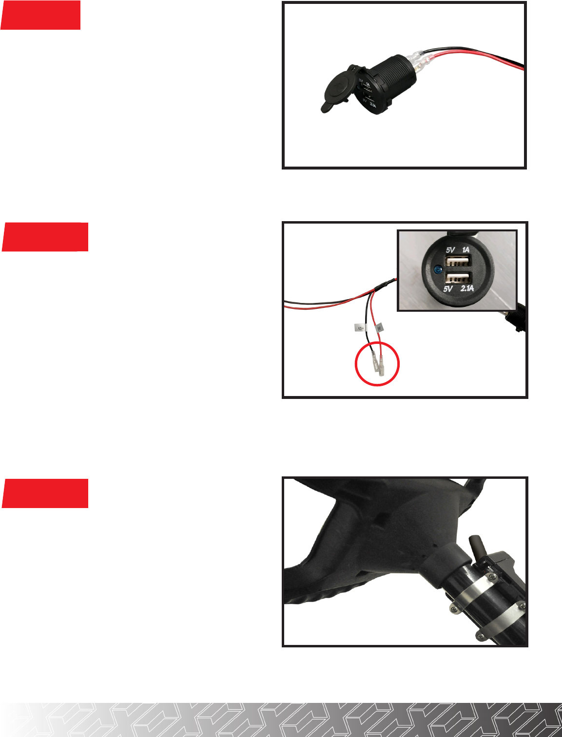
Using a 1-1/8” Paddle Bit, find a desired location on your
golf cart dashboard to mount your USB charger. Ensure
your location is free of obstacles and will not aect dash
reattachment.
NOTE: If you do not have access to a 1-1/8” Paddle Bit you
can use the inside of the USB ring nut as a template.
*USB CHARGER INSTALL*
Using the USB ring nut, secure the charger to your cart.
Attach the red & black connectors from the light kit
harness to the spade terminals on the back of the
charger, red to (+) and black to (-).
NOTE: Secondary connectors can be used to supply
power to another 12 volt accessory with less than 7.5 amp
draw.
Mount Turn Signal Indicator assembly using clamps
provided and tighten clamps evenly. Run Turn Signal
Indicator harness along steering column and insert
harness through dash.
*TURN ASSEMBLY INSTALL*
*optional 12v accessory hookups

STEP 12
STEP 13
STEP 14
Attach back cover to turn signal assembly.
Attach column cover to steering column, secure harness
in column cover void.
NOTE: The hazard switch is pre-installed to the Turn Signal
housing. No additional steps are required to install hazard
switch.
Attach horn to purple and black female spade
connectors from front of harness and secure horn to
metal framework under front cowl with a self tapping
screw.
NOTE: Wires have no orientation and will work on either
post.
Auxiliary rotary
switch
The turn signal handle has a secondary, 2-position rotary
switch for auxiliary 12 volt lighting such as fog lights and/
or LED light bars. There is one common negative wire
and two positive wire connections to run two dierent
auxiliary lights.
Additional wiring and lighting not included. Reinstall
dashboard using retained hardware from Step 6.
*AUXILIARY SWITCH FEATURE*

Front of Cart
Jam Nut
STEP 15
A) Loosen jam nut on brake rod using a 1/2” wrench.
Place the forked bracket around the brake rod behind
the Jam nut and tighten the Jam nut sandwiching the
bracket. Place the brake switch on the floor of the car
with the spring running towards the back of the car to
the brake switch.
B) Adjust the brake switch so that the spring has no
slack but the switch is not engaged. Screw the brake
switch to the floor of the car with self tapping screws.
C) Plug the 2 bullet connectors from the brake switch
into the corresponding bullet connectors on the light
kit harness. Secure all wiring so that it is away from
moving parts.
A
NOTE: Disengage Brake before and during brake switch
installation.
*BRAKE SWITCH INSTALL*
B
Brake Pad Harness
Alpha Bucket Harness
C

Attach the smallest 1.5” bracket to top inside mounting tab.
Attach 2.25” bracket to remaining mounting tab. Be sure
that the slotted holes are facing towards the head light
opening.
Attach two of the 2” headlight brackets to the bottom tabs
of the cowl using the large head half inch screw as shown.
Be sure that the slotted holes are facing towards the
headlight opening.
To mount the front headlights, the 8 small brackets pictured
will be used. There are three dierent sized brackets that
all have specific locations where they need to be mounted.
STEP 16
STEP 17
STEP 18
(2) 2.25”
(4) 2”
(4) 1.5”
half inch
slotted end
2.25”
1.5”

With cowl flipped over, be sure your light tab bracket
locations are the same as the picture shown.
Place the supplied rubber seal around the headlight
and insert light into cowl as shown.
Using the 1 inch screws and springs from hardware
pack, attach the headlight to the mounting tabs as
shown.
Be sure the screws and springs are attached as
shown with the springs between the light housing
and mounting brackets. If lights are not lining up flush,
loosen screws and adjust accordingly.
Repeat process on the other side.
STEP 19
STEP 20
STEP 21
2.25”
2” 2”
1.5”

STEP A
STEP B
STEP C
ATTENTION: For Ultimate Plus Light Kit Instructions (02-130), skip to Step 22.
Plug 3 Pin Connector from LUX Module to 3-Pin on
Headlights as shown.
Connect the 4-Pin Connector from Main Harness to
4-Pin Connector on Headlight.
At the front of the car, connect the 2-Pin connector
from LUX Module to the Main Harness.
OPTIONAL MODULE INSTALL FOR 02-107 ALPHA LUX LIGHT KIT
Optional Module
for 02-107
To access the features of your LUX Module download the Happy Light App and follow the provided instructions.
OPTIONAL MODULE INSTALL COMPLETE

Locate the pre-drilled hole shown in your underbody.
Plug tail light harness into bucket harness. Red
connectors go to the passenger side.
(Passenger Side)
STEP 23
STEP 24
Using the 8mmx45mm hardware, attach light
mounting bracket to underbody from tire well as
shown. Once bolt is started, tighten. For any warranty
purposes, this will be a way to quicly remove the tail
lights.
Repeat process on other side. Reattach all factory
seats, top, struts, etc.
STEP 25
Take passenger tail light (with red 4 pin connector) and
attach the passenger side tail light bracket labeled (P)
using the screws provided.
STEP 22
STEP 26
Now that power is connected check brake switch operation. Make adjustments if needed by repeating Step 15.
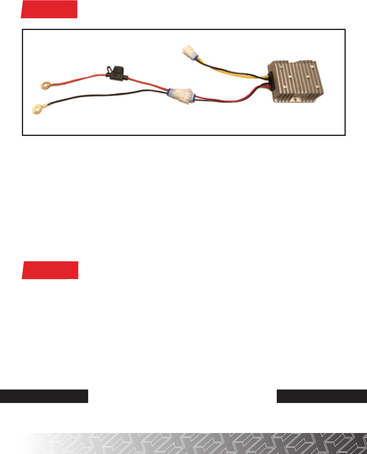
The voltage converter included must be used on all carts electric and gas. Ensure the red & black pigtail harness with ring
terminals above is disconnected from the converter and/or bucket harness. Then connect the red wire with the fuse to the
main positive terminal of the battery pack. Connect the black wire to the main negative terminal of the battery pack and
tighten hardware.
Mount the converter to a flat surface under the seat within range of the pigtail harness. (Metal area is preferred). Plug the
connector with the yellow and black wire from the converter into the light kit harness. Finally, connect the red and black
connector from the converter to the pigtail harness (you will notice a small arc in the connectors). You can now place run/
tow switch back to run.
*Use converter on gas carts to prevent Starter Generator voltage spikes that could cause damage to accessories.
Plugs into Light Kit Harness
Main Positive
STEP 27
Plugs into
Light Kit Harness
Main Positive
Main Negative
Pigtail Harness Converter
(+)
(-)
*CONVERTER AND POWER HOOKUP*
INSTALLATION COMPLETE
E-Z-GO
®
, TXT
®
, RXV
®
and S4
®
are registered trademarks of Textron Innovations, Inc. Club Car
®
, Precedent
®
, DS
®
, Onward
®
and Tempo
®
are registered trademarks of Ingersoll Rand, Inc. Yamaha
®
, Yamaha
®
Drive
®
, Drive2
®
,
G-14
®
, G-16
®
, G-19
®
, G-22
®
and G-29
®
are registered trademarks of Yamaha Golf-Car Company. Any reference to Club Car
®
, E-Z-GO
®
, or Yamaha
®
or their associated trademarks, word
marks, and products are only for purposes of identifying golf carts with which this MadJax product is compatible. MadJax products are aftermarket parts and are not original equipment parts. MadJax
is not connected to, aliated with, sponsored by, or endorsed by either Textron Innovations, Inc., Ingersoll Rand, Inc., Yamaha Golf Cart Company, or any of their parent or subsidiary companies.

Optional 12v
Accessory
USB
Driver Headlight
Passenger Headlight
LUX (for 02-107 only)
To Turn Signal 12 Pin
To Bucket Harness 12 pin
ALPHA FRONT HARNESS
WIRING LEGEND
Horn

To 48-12v
Converter
Driver
Taillight
Brake Switch
Connections
To Alpha
Front Harness 12 pin
(Front of Harness)
Passenger
Taillight
ALPHA BUCKET HARNESS
WIRING LEGEND
