
2009 Edition Page 547
CHAPTER 6A. GENERAL
Section 6A.01 General
Support:
01 Whenever the acronym “TTC” is used in Part 6, it refers to “temporary trafc control.”
Standard:
02 The needs and control of all road users (motorists, bicyclists, and pedestrians within the highway, or on
private roads open to public travel (see denition in Section 1A.13), including persons with disabilities in
accordance with the Americans with Disabilities Act of 1990 (ADA), Title II, Paragraph 35.130) through a
TTC zone shall be an essential part of highway construction, utility work, maintenance operations, and the
management of trafc incidents.
Support:
03 When the normal function of the roadway, or a private road open to public travel, is suspended, TTC planning
provides for continuity of the movement of motor vehicle, bicycle, and pedestrian trafc (including accessible
passage); transit operations; and access (and accessibility) to property and utilities.
04 The primary function of TTC is to provide for the reasonably safe and effective movement of road users
through or around TTC zones while reasonably protecting road users, workers, responders to trafc incidents,
and equipment.
05 Of equal importance to the public traveling through the TTC zone is the safety of workers performing the
many varied tasks within the work space. TTC zones present constantly changing conditions that are unexpected
by the road user. This creates an even higher degree of vulnerability for the workers and incident management
responders on or near the roadway (see Section 6D.03). At the same time, the TTC zone provides for the efcient
completion of whatever activity interrupted the normal use of the roadway.
06 Consideration for road user safety, worker and responder safety, and the efciency of road user ow is an
integral element of every TTC zone, from planning through completion. A concurrent objective of the TTC is the
efcient construction and maintenance of the highway and the efcient resolution of trafc incidents.
07 No one set of TTC devices can satisfy all conditions for a given project or incident. At the same time,
dening details that would be adequate to cover all applications is not practical. Instead, Part 6 displays typical
applications that depict common applications of TTC devices. The TTC selected for each situation depends on
type of highway, road user conditions, duration of operation, physical constraints, and the nearness of the work
space or incident management activity to road users.
08 Improved road user performance might be realized through a well-prepared public relations effort that covers
the nature of the work, the time and duration of its execution, the anticipated effects upon road users, and possible
alternate routes and modes of travel. Such programs have been found to result in a signicant reduction in the
number of road users traveling through the TTC zone, which reduces the possible number of conicts.
09 Operational improvements might be realized by using intelligent transportation systems (ITS) in work zones.
The use in work zones of ITS technology, such as portable camera systems, highway advisory radio, variable
speed limits, ramp metering, traveler information, merge guidance, and queue detection information, is aimed at
increasing safety for both workers and road users and helping to ensure a more efcient trafc ow. The use in
work zones of ITS technologies has been found to be effective in providing trafc monitoring and management,
data collection, and traveler information.
Standard:
10 TTC plans and devices shall be the responsibility of the authority of a public body or ofcial having
jurisdiction for guiding road users. There shall be adequate statutory authority for the implementation and
enforcement of needed road user regulations, parking controls, speed zoning, and the management of trafc
incidents. Such statutes shall provide sufcient exibility in the application of TTC to meet the needs of
changing conditions in the TTC zone.
Support:
11 Temporary facilities, including pedestrian routes around worksites, are also covered by the accessibility
requirements of the Americans with Disabilities Act of 1990 (ADA) (Public Law 101-336, 104 Stat. 327, July 26,
1990. 42 U.S.C. 12101-12213 (as amended)).
PART 6
TEMPORARY TRAFFIC CONTROL
December 2009 Sect. 6A.01

Page 548 2009 Edition
Guidance:
12 The TTC plan should start in the planning phase and continue through the design, construction, and
restoration phases. The TTC plans and devices should follow the principles set forth in Part 6. The management
of trafc incidents should follow the principles set forth in Chapter 6I.
Option:
13 TTC plans may deviate from the typical applications described in Chapter 6H to allow for conditions and
requirements of a particular site or jurisdiction.
Support:
14 The provisions of Part 6 apply to both rural and urban areas. A rural highway is normally characterized
by lower volumes, higher speeds, fewer turning conicts, and less conict with pedestrians. An urban street
is typically characterized by relatively low speeds, wide ranges of road user volumes, narrower roadway lanes,
frequent intersections and driveways, signicant pedestrian activity, and more businesses and houses.
15 The determination as to whether a particular facility at a particular time of day can be considered to be a
high-volume roadway or can be considered to be a low-volume roadway is made by the public agency or ofcial
having jurisdiction.
Sect. 6A.01 December 2009

2009 Edition Page 549
CHAPTER 6B. FUNDAMENTAL PRINCIPLES
Section 6B.01 Fundamental Principles of Temporary Trafc Control
Support:
01 Construction, maintenance, utility, and incident zones can all benet from TTC to compensate for the
unexpected or unusual situations faced by road users. When planning for TTC in these zones, it can be assumed
that it is appropriate for road users to exercise caution. Even though road users are assumed to be using caution,
special care is still needed in applying TTC techniques.
02 Special plans preparation and coordination with transit, other highway agencies, law enforcement and other
emergency units, utilities, schools, and railroad companies might be needed to reduce unexpected and unusual
road user operation situations.
03 During TTC activities, commercial vehicles might need to follow a different route from passenger vehicles
because of bridge, weight, clearance, or geometric restrictions. Also, vehicles carrying hazardous materials might
need to follow a different route from other vehicles. The Hazardous Materials and National Network signs are
included in Sections 2B.62 and 2B.63, respectively.
04 Experience has shown that following the fundamental principles of Part 6 will assist road users and help
protect workers in the vicinity of TTC zones.
Guidance:
05 Road user and worker safety and accessibility in TTC zones should be an integral and high-priority element
of every project from planning through design and construction. Similarly, maintenance and utility work should
be planned and conducted with the safety and accessibility of all motorists, bicyclists, pedestrians (including
those with disabilities), and workers being considered at all times. If the TTC zone includes a grade crossing,
early coordination with the railroad company or light rail transit agency should take place.
Support:
06 Formulating specic plans for TTC at trafc incidents is difcult because of the variety of situations that
can arise.
Guidance:
07 The following are the seven fundamental principles of TTC:
1. General plans or guidelines should be developed to provide safety for motorists, bicyclists, pedestrians,
workers, enforcement/emergency ofcials, and equipment, with the following factors being considered:
A. The basic safety principles governing the design of permanent roadways and roadsides should also
govern the design of TTC zones. The goal should be to route road users through such zones using
roadway geometrics, roadside features, and TTC devices as nearly as possible comparable to those
for normal highway situations.
B. A TTC plan, in detail appropriate to the complexity of the work project or incident, should be
prepared and understood by all responsible parties before the site is occupied. Any changes in the
TTC plan should be approved by an ofcial who is knowledgeable (for example, trained and/or
certied) in proper TTC practices.
2. Road user movement should be inhibited as little as practical, based on the following considerations:
A. TTC at work and incident sites should be designed on the assumption that drivers will only reduce
their speeds if they clearly perceive a need to do so (see Section 6C.01).
B. Frequent and abrupt changes in geometrics such as lane narrowing, dropped lanes, or main roadway
transitions that require rapid maneuvers, should be avoided.
C. Work should be scheduled in a manner that minimizes the need for lane closures or alternate routes,
while still getting the work completed quickly and the lanes or roadway open to trafc as soon
as possible.
D. Attempts should be made to reduce the volume of trafc using the roadway or freeway to match the
restricted capacity conditions. Road users should be encouraged to use alternative routes. For high-
volume roadways and freeways, the closure of selected entrance ramps or other access points and the
use of signed diversion routes should be evaluated.
E. Bicyclists and pedestrians, including those with disabilities, should be provided with access and
reasonably safe passage through the TTC zone.
F. If work operations permit, lane closures on high-volume streets and highways should be scheduled
during off-peak hours. Night work should be considered if the work can be accomplished with a
series of short-term operations.
G. Early coordination with ofcials having jurisdiction over the affected cross streets and providing
emergency services should occur if signicant impacts to roadway operations are anticipated.
3. Motorists, bicyclists, and pedestrians should be guided in a clear and positive manner while approaching
and traversing TTC zones and incident sites. The following principles should be applied:
December 2009 Sect. 6B.01

Page 550 2009 Edition
A. Adequate warning, delineation, and channelization should be provided to assist in guiding road users
in advance of and through the TTC zone or incident site by using proper pavement marking, signing,
or other devices that are effective under varying conditions. Providing information that is in usable
formats by pedestrians with visual disabilities should also be considered.
B. TTC devices inconsistent with intended travel paths through TTC zones should be removed or
covered. However, in intermediate-term stationary, short-term, and mobile operations, where visible
permanent devices are inconsistent with intended travel paths, devices that highlight or emphasize
the appropriate path should be used. Providing trafc control devices that are accessible to and
usable by pedestrians with disabilities should be considered.
C. Flagging procedures, when used, should provide positive guidance to road users traversing the
TTC zone.
4. To provide acceptable levels of operations, routine day and night inspections of TTC elements should be
performed as follows:
A. Individuals who are knowledgeable (for example, trained and/or certied) in the principles of proper
TTC should be assigned responsibility for safety in TTC zones. The most important duty of these
individuals should be to check that all TTC devices of the project are consistent with the TTC plan
and are effective for motorists, bicyclists, pedestrians, and workers.
B. As the work progresses, temporary trafc controls and/or working conditions should be modied,
if appropriate, in order to provide mobility and positive guidance to the road user and to provide
worker safety. The individual responsible for TTC should have the authority to halt work until
applicable or remedial safety measures are taken.
C. TTC zones should be carefully monitored under varying conditions of road user volumes, light, and
weather to check that applicable TTC devices are effective, clearly visible, clean, and in compliance
with the TTC plan.
D. When warranted, an engineering study should be made (in cooperation with law enforcement
ofcials) of reported crashes occurring within the TTC zone. Crash records in TTC zones should be
monitored to identify the need for changes in the TTC zone.
5. Attention should be given to the maintenance of roadside safety during the life of the TTC zone by
applying the following principles:
A. To accommodate run-off-the-road incidents, disabled vehicles, or emergency situations,
unencumbered roadside recovery areas or clear zones should be provided where practical.
B. Channelization of road users should be accomplished by the use of pavement markings, signing, and
crashworthy, detectable channelizing devices.
C. Work equipment, workers’ private vehicles, materials, and debris should be stored in such a manner
to reduce the probability of being impacted by run-off-the-road vehicles.
6. Each person whose actions affect TTC zone safety, from the upper-level management through the eld
workers, should receive training appropriate to the job decisions each individual is required to make.
Only those individuals who are trained in proper TTC practices and have a basic understanding of the
principles (established by applicable standards and guidelines, including those of this Manual) should
supervise the selection, placement, and maintenance of TTC devices used for TTC zones and for incident
management.
7. Good public relations should be maintained by applying the following principles:
A. The needs of all road users should be assessed such that appropriate advance notice is given and
clearly dened alternative paths are provided.
B. The cooperation of the various news media should be sought in publicizing the existence of and
reasons for TTC zones because news releases can assist in keeping the road users well informed.
C. The needs of abutting property owners, residents, and businesses should be assessed and appropriate
accommodations made.
D. The needs of emergency service providers (law enforcement, re, and medical) should be assessed
and appropriate coordination and accommodations made.
E. The needs of railroads and transit should be assessed and appropriate coordination and
accommodations made.
F. The needs of operators of commercial vehicles such as buses and large trucks should be assessed and
appropriate accommodations made.
Standard:
08 Before any new detour or temporary route is opened to trafc, all necessary signs shall be in place.
09 All TTC devices shall be removed as soon as practical when they are no longer needed. When work
is suspended for short periods of time, TTC devices that are no longer appropriate shall be removed
or covered.
Sect. 6B.01 December 2009

2009 Edition Page 551
CHAPTER 6C. TEMPORARY TRAFFIC CONTROL ELEMENTS
Section 6C.01 Temporary Trafc Control Plans
Support:
01 A TTC plan describes TTC measures to be used for facilitating road users through a work zone or an incident
area. TTC plans play a vital role in providing continuity of effective road user ow when a work zone, incident, or
other event temporarily disrupts normal road user ow. Important auxiliary provisions that cannot conveniently be
specied on project plans can easily be incorporated into Special Provisions within the TTC plan.
02 TTC plans range in scope from being very detailed to simply referencing typical drawings contained in this
Manual, standard approved highway agency drawings and manuals, or specic drawings contained in the contract
documents. The degree of detail in the TTC plan depends entirely on the nature and complexity of the situation.
Guidance:
03 TTC plans should be prepared by persons knowledgeable (for example, trained and/or certied) about the
fundamental principles of TTC and work activities to be performed. The design, selection, and placement of
TTC devices for a TTC plan should be based on engineering judgment.
04 Coordination should be made between adjacent or overlapping projects to check that duplicate signing is not
used and to check compatibility of trafc control between adjacent or overlapping projects.
05 Trafc control planning should be completed for all highway construction, utility work, maintenance
operations, and incident management including minor maintenance and utility projects prior to occupying the
TTC zone. Planning for all road users should be included in the process.
06 Provisions for effective continuity of accessible circulation paths for pedestrians should be incorporated
into the TTC process. Where existing pedestrian routes are blocked or detoured, information should be provided
about alternative routes that are usable by pedestrians with disabilities, particularly those who have visual
disabilities. Access to temporary bus stops, travel across intersections with accessible pedestrian signals
(see Section 4E.09), and other routing issues should be considered where temporary pedestrian routes are
channelized. Barriers and channelizing devices that are detectable by people with visual disabilities should
be provided.
Option:
07 Provisions may be incorporated into the project bid documents that enable contractors to develop an alternate
TTC plan.
08 Modications of TTC plans may be necessary because of changed conditions or a determination of better
methods of safely and efciently handling road users.
Guidance:
09 This alternate or modied plan should have the approval of the responsible highway agency prior
to implementation.
10 Provisions for effective continuity of transit service should be incorporated into the TTC planning
process because often public transit buses cannot efciently be detoured in the same manner as other vehicles
(particularly for short-term maintenance projects). Where applicable, the TTC plan should provide for features
such as accessible temporary bus stops, pull-outs, and satisfactory waiting areas for transit patrons, including
persons with disabilities, if applicable (see Section 8A.08 for additional light rail transit issues to consider
for TTC).
11 Provisions for effective continuity of railroad service and acceptable access to abutting property owners and
businesses should also be incorporated into the TTC planning process.
12 Reduced speed limits should be used only in the specic portion of the TTC zone where conditions or
restrictive features are present. However, frequent changes in the speed limit should be avoided. A TTC plan
should be designed so that vehicles can travel through the TTC zone with a speed limit reduction of no more
than 10 mph.
13 A reduction of more than 10 mph in the speed limit should be used only when required by restrictive features
in the TTC zone. Where restrictive features justify a speed reduction of more than 10 mph, additional driver
notication should be provided. The speed limit should be stepped down in advance of the location requiring the
lowest speed, and additional TTC warning devices should be used.
14 Reduced speed zoning (lowering the regulatory speed limit) should be avoided as much as practical because
drivers will reduce their speeds only if they clearly perceive a need to do so.
December 2009 Sect. 6C.01

Page 552 2009 Edition
Support:
15 Research has demonstrated that large reductions in the speed limit, such as a 30 mph reduction, increase
speed variance and the potential for crashes. Smaller reductions in the speed limit of up to 10 mph cause smaller
changes in speed variance and lessen the potential for increased crashes. A reduction in the regulatory speed limit
of only up to 10 mph from the normal speed limit has been shown to be more effective.
Section 6C.02 Temporary Trafc Control Zones
Support:
01 A TTC zone is an area of a highway where road user conditions are changed because of a work zone, an
incident zone, or a planned special event through the use of TTC devices, uniformed law enforcement ofcers,
or other authorized personnel.
02 A work zone is an area of a highway with construction, maintenance, or utility work activities. A work zone
is typically marked by signs, channelizing devices, barriers, pavement markings, and/or work vehicles. It extends
from the rst warning sign or high-intensity rotating, ashing, oscillating, or strobe lights on a vehicle to the END
ROAD WORK sign or the last TTC device.
03 An incident zone is an area of a highway where temporary trafc controls are imposed by authorized ofcials
in response to a trafc incident (see Section 6I.01). It extends from the rst warning device (such as a sign, light,
or cone) to the last TTC device or to a point where road users return to the original lane alignment and are clear of
the incident.
04 A planned special event often creates the need to establish altered trafc patterns to handle the increased
trafc volumes generated by the event. The size of the TTC zone associated with a planned special event can
be small, such as closing a street for a festival, or can extend throughout a municipality for larger events. The
duration of the TTC zone is determined by the duration of the planned special event.
Section 6C.03 Components of Temporary Trafc Control Zones
Support:
01 Most TTC zones are divided into four areas: the advance warning area, the transition area, the activity area,
and the termination area. Figure 6C-1 illustrates these four areas. These four areas are described in Sections
6C.04 through 6C.07.
Section 6C.04 Advance Warning Area
Support:
01 The advance warning area is the section of highway where road users are informed about the upcoming work
zone or incident area.
Option:
02 The advance warning area may vary from a single sign or high-intensity rotating, ashing, oscillating, or
strobe lights on a vehicle to a series of signs in advance of the TTC zone activity area.
Guidance:
03 Typical distances for placement of advance warning signs on freeways and expressways should be longer
because drivers are conditioned to uninterrupted ow. Therefore, the advance warning sign placement should
extend on these facilities as far as 1/2 mile or more.
04 On urban streets, the effective placement of the rst warning sign in feet should range from 4 to 8 times the
speed limit in mph, with the high end of the range being used when speeds are relatively high. When a single
advance warning sign is used (in cases such as low-speed residential streets), the advance warning area can be
as short as 100 feet. When two or more advance warning signs are used on higher-speed streets, such as major
arterials, the advance warning area should extend a greater distance (see Table 6C-1).
05 Since rural highways are normally characterized by higher speeds, the effective placement of the rst
warning sign in feet should be substantially longer—from 8 to 12 times the speed limit in mph. Since two or more
advance warning signs are normally used for these conditions, the advance warning area should extend 1,500
feet or more for open highway conditions (see Table 6C-1).
06 The distances contained in Table 6C-1 are approximate, are intended for guidance purposes only, and should
be applied with engineering judgment. These distances should be adjusted for eld conditions, if necessary, by
increasing or decreasing the recommended distances.
Sect. 6C.01 to 6C.04 December 2009

2009 Edition Page 553
Buffer Space
(longitudinal)
provides protection for
traffic and workers
Buffer Space
(lateral)
provides
protection
for traffic
and workers
Buffer Space (longitudinal)
Shoulder Taper
Termination Area
lets traffic resume
normal operations
Activity Area
is where work
takes place
Transition Area
moves traffic out
of its normal path
Advance Warning Area
tells traffic what to
expect ahead
Work Space
is set aside for
workers, equipment,
and material storage
Downstream Taper
Traffic Space
allows traffic
to pass through
the activity area
Figure 6C-1. Component Parts of a Temporary Traffic Control Zone
Legend
Direction of travel
Channelizing device
Work space
Sign
December 2009 Sect. 6C.04

Page 554 2009 Edition
Support:
07 The need to provide additional reaction time for a condition is one example of justication for increasing
the sign spacing. Conversely, decreasing the sign spacing might be justied in order to place a sign immediately
downstream of an intersection or major driveway such that trafc turning onto the roadway in the direction of the
TTC zone will be warned of the upcoming condition.
Option:
08 Advance warning may be eliminated when the activity area is sufciently removed from the road users’ path
so that it does not interfere with the normal ow.
Section 6C.05 Transition Area
Support:
01 The transition area is that section of highway where road users are redirected out of their normal path.
Transition areas usually involve strategic use of tapers, which because of their importance are discussed separately
in detail.
Standard:
02 When redirection of the road users’ normal path is required, they shall be directed from the normal
path to a new path.
Option:
03 Because it is impractical in mobile operations to redirect the road user’s normal path with stationary
channelization, more dominant vehicle-mounted trafc control devices, such as arrow boards, portable changeable
message signs, and high-intensity rotating, ashing, oscillating, or strobe lights, may be used instead of
channelizing devices to establish a transition area.
Section 6C.06 Activity Area
Support:
01 The activity area is the section of the highway where the work activity takes place. It is comprised of the work
space, the trafc space, and the buffer space.
02 The work space is that portion of the highway closed to road users and set aside for workers, equipment, and
material, and a shadow vehicle if one is used upstream. Work spaces are usually delineated for road users by
channelizing devices or, to exclude vehicles and pedestrians, by temporary barriers.
Option:
03 The work space may be stationary or may move as work progresses.
Guidance:
04 Since there might be several work spaces (some even separated by several miles) within the project limits,
each work space should be adequately signed to inform road users and reduce confusion.
Support:
05 The trafc space is the portion of the highway in which road users are routed through the activity area.
Table 6C-1. Recommended Advance Warning Sign Minimum Spacing
Road Type
Distance Between Signs**
A B C
Urban (low speed)* 100 feet 100 feet 100 feet
Urban (high speed)* 350 feet 350 feet 350 feet
Rural 500 feet 500 feet 500 feet
Expressway / Freeway 1,000 feet 1,500 feet 2,640 feet
* Speed category to be determined by the highway agency
** The column headings A, B, and C are the dimensions shown in Figures 6H-1 through 6H-46. The A
dimension is the distance from the transition or point of restriction to the first sign. The B dimension
is the distance between the first and second signs. The C dimension is the distance between the
second and third signs. (The “first sign” is the sign in a three-sign series that is closest to the TTC
zone. The “third sign” is the sign that is furthest upstream from the TTC zone.)
Sect. 6C.04 to 6C.06 December 2009

2009 Edition Page 555
06 The buffer space is a lateral and/or longitudinal area that separates road user ow from the work space or an
unsafe area, and might provide some recovery space for an errant vehicle.
Guidance:
07 Neither work activity nor storage of equipment, vehicles, or material should occur within a buffer space.
Option:
08 Buffer spaces may be positioned either longitudinally or laterally with respect to the direction of road user
ow. The activity area may contain one or more lateral or longitudinal buffer spaces.
09 A longitudinal buffer space may be placed in advance of a work space.
10 The longitudinal buffer space may also be used to separate opposing road user ows that use portions of the
same trafc lane, as shown in Figure 6C-2.
11 If a longitudinal buffer space is used, the values shown
in Table 6C-2 may be used to determine the length of the
longitudinal buffer space.
Support:
12 Typically, the buffer space is formed as a trafc island
and dened by channelizing devices.
13 When a shadow vehicle, arrow board, or changeable
message sign is placed in a closed lane in advance of
a work space, only the area upstream of the vehicle,
arrow board, or changeable message sign constitutes the
buffer space.
Option:
14 The lateral buffer space may be used to separate the
trafc space from the work space, as shown in Figures
6C-1 and 6C-2, or such areas as excavations or pavement-
edge drop-offs. A lateral buffer space also may be used
between two travel lanes, especially those carrying
opposing ows.
Guidance:
15 The width of a lateral buffer space should be
determined by engineering judgment.
Option:
16 When work occurs on a high-volume, highly congested facility, a vehicle storage or staging space may be
provided for incident response and emergency vehicles (for example, tow trucks and re apparatus) so that these
vehicles can respond quickly to road user incidents.
Section 6C.07 Termination Area
Support:
01 The termination area is the section of the highway where road users are returned to their normal driving path.
The termination area extends from the downstream end of the work area to the last TTC device such as END
ROAD WORK signs, if posted.
Option:
02 An END ROAD WORK sign, a Speed Limit sign, or other signs may be used to inform road users that they
can resume normal operations.
03 A longitudinal buffer space may be used between the work space and the beginning of the downstream taper.
Section 6C.08 Tapers
Option:
01 Tapers may be used in both the transition and termination areas. Whenever tapers are to be used in close
proximity to an interchange ramp, crossroads, curves, or other inuencing factors, the length of the tapers may
be adjusted.
Support:
02 Tapers are created by using a series of channelizing devices and/or pavement markings to move trafc out of
or into the normal path. Types of tapers are shown in Figure 6C-2.
Table 6C-2. Stopping Sight Distance
as a Function of Speed
Speed* Distance
20 mph 115 feet
25 mph 155 feet
30 mph 200 feet
35 mph 250 feet
40 mph 305 feet
45 mph 360 feet
50 mph 425 feet
55 mph 495 feet
60 mph 570 feet
65 mph 645 feet
70 mph 730 feet
75 mph 820 feet
* Posted speed, off-peak 85th-percentile speed prior to work
starting, or the anticipated operating speed
December 2009 Sect. 6C.06 to 6C.08

Page 556 2009 Edition
Downstream Taper
(optional)
Longitudinal Buffer
Space (optional)
Shifting
Taper
1/2 L
Longitudinal Buffer
Space (optional)
Shoulder
Taper
1/3 L
Longitudinal
Buffer Space
(optional)
Merging
Taper
Shifting
Taper
Lateral Buffer Space
(optional)
Shifting
Taper
4S ft*
1/2 L
1/2 L
Figure 6C-2. Types of Tapers and Buffer Spaces
*S = speed in mph
Legend
Direction of travel
Channelizing device
Work space
Sign
Sect. 6C.08 December 2009

2009 Edition Page 557
03 Longer tapers are not necessarily better than shorter tapers (particularly in urban areas with characteristics
such as short block lengths or driveways) because extended tapers tend to encourage sluggish operation and to
encourage drivers to delay lane changes unnecessarily. The test concerning adequate lengths of tapers involves
observation of driver performance after TTC plans are put into effect.
Guidance:
04 The appropriate taper length (L) should
be determined using the criteria shown in
Tables 6C-3 and 6C-4.
05 The maximum distance in feet between
devices in a taper should not exceed 1.0 times
the speed limit in mph.
Support:
06 A merging taper requires the longest
distance because drivers are required to merge
into common road space.
Guidance:
07 A merging taper should be long enough
to enable merging drivers to have adequate
advance warning and sufcient length
to adjust their speeds and merge into an
adjacent lane before the downstream end of
the transition.
Support:
08 A shifting taper is used when a lateral
shift is needed. When more space is available,
a longer than minimum taper distance can
be benecial. Changes in alignment can also
be accomplished by using horizontal curves
designed for normal highway speeds.
Guidance:
09 A shifting taper should have a length
of approximately 1/2 L (see Tables 6C-3
and 6C-4).
Support:
10 A shoulder taper might be benecial on a high-speed roadway where shoulders are part of the a ctivity area
and are closed, or when improved shoulders might be mistaken as a driving lane. In these instances, the same
type, but abbreviated, closure procedures used on a normal portion of the roadway can be used.
Guidance:
11 If used, shoulder tapers should have a length of approximately 1/3 L (see Tables 6C-3 and 6C-4). If a
shoulder is used as a travel lane, either through practice or during a TTC activity, a normal merging or shifting
taper should be used.
Support:
12 A downstream taper might be useful in termination areas to provide a visual cue to the driver that access is
available back into the original lane or path that was closed.
Guidance:
13 If used, a downstream taper should have a minimum length of 50 feet and a maximum length of 100 feet with
devices placed at a spacing of approximately 20 feet.
Support:
14 The one-lane, two-way taper is used in advance of an activity area that occupies part of a two-way roadway in
such a way that a portion of the road is used alternately by trafc in each direction.
Guidance:
15 Trafc should be controlled by a agger or temporary trafc control signal (if sight distance is limited), or a
STOP or YIELD sign. A short taper having a minimum length of 50 feet and a maximum length of 100 feet with
channelizing devices at approximately 20-foot spacing should be used to guide trafc into the one-lane section,
and a downstream taper should be used to guide trafc back into their original lane.
Table 6C-3. Taper Length Criteria for
Temporary Traffic Control Zones
Type of Taper Taper Length
Merging Taper at least L
Shifting Taper at least 0.5 L
Shoulder Taper at least 0.33 L
One-Lane, Two-Way Traffic Taper 50 feet minimum, 100 feet maximum
Downstream Taper 50 feet minimum, 100 feet maximum
Note: Use Table 6C-4 to calculate L
Table 6C-4. Formulas for Determining
Taper Length
Speed (S) Taper Length (L) in feet
40 mph or less L =
WS
2
60
45 mph or more L = WS
Where: L = taper length in feet
W = width of offset in feet
S = posted speed limit, or off-peak 85th-percentile speed prior
to work starting, or the anticipated operating speed in mph
December 2009 Sect. 6C.08

Page 558 2009 Edition
Support:
16 An example of a one-lane, two-way trafc taper is shown in Figure 6C-3.
Section 6C.09 Detours and Diversions
Support:
01 A detour is a temporary rerouting of road users onto an existing highway in order to avoid a TTC zone.
Guidance:
02 Detours should be clearly signed over their entire length so that road users can easily use existing highways to
return to the original highway.
Support:
03 A diversion is a temporary rerouting of road users onto a temporary highway or alignment placed around the
work area.
Section 6C.10 One-Lane, Two-Way Trafc Control
Standard:
01 Except as provided in Paragraph 5, when trafc in both directions must use a single lane for a limited
distance, movements from each end shall be coordinated.
Guidance:
02 Provisions should be made for alternate one-way movement through the constricted section via methods such
as agger control, a ag transfer, a pilot car, trafc control signals, or stop or yield control.
03 Control points at each end should be chosen to permit easy passing of opposing lanes of vehicles.
04 If trafc on the affected one-lane roadway is not visible from one end to the other, then agging procedures,
a pilot car with a agger used as described in Section 6C.13, or a trafc control signal should be used to control
opposing trafc ows.
Option:
05 If the work space on a low-volume street or road is short and road users from both directions are able to see
the trafc approaching from the opposite direction through and beyond the worksite, the movement of trafc
through a one-lane, two-way constriction may be self-regulating.
Section 6C.11 Flagger Method of One-Lane, Two-Way Trafc Control
Guidance:
01 Except as provided in Paragraph 2, trafc should be controlled by a agger at each end of a constricted
section of roadway. One of the aggers should be designated as the coordinator. To provide coordination of the
control of the trafc, the aggers should be able to communicate with each other orally, electronically, or with
manual signals. These manual signals should not be mistaken for agging signals.
Option:
02 When a one-lane, two-way TTC zone is short enough to allow a agger to see from one end of the zone to the
other, trafc may be controlled by either a single agger or by a agger at each end of the section.
Guidance:
03 When a single agger is used, the agger should be stationed on the shoulder opposite the constriction or
work space, or in a position where good visibility and trafc control can be maintained at all times. When good
visibility and trafc control cannot be maintained by one agger station, trafc should be controlled by a agger
at each end of the section.
Section 6C.12 Flag Transfer Method of One-Lane, Two-Way Trafc Control
Support:
01 The driver of the last vehicle proceeding into the one-lane section is given a red ag (or other token) and
instructed to deliver it to the agger at the other end. The opposite agger, upon receipt of the ag, then knows
that trafc can be permitted to move in the other direction. A variation of this method is to replace the use of a
ag with an ofcial pilot car that follows the last road user vehicle proceeding through the section.
Guidance:
02 The ag transfer method should be employed only where the one-way trafc is conned to a relatively short
length of a road, usually no more than 1 mile in length.
Sect. 6C.08 to 6C.12 December 2009

2009 Edition Page 559
Buffer Space
(longitudinal)
Downstream Taper
50 to 100 ft
Work Space
Buffer Space (longitudinal)
is used to position the taper
in advance of the curve
One-Lane, Two-Way Traffic Taper
50 to 100 ft
Legend
Figure 6C-3. Example of a One-Lane, Two-Way Traffic Taper
December 2009 Sect. 6C.12

Page 560 2009 Edition
Section 6C.13 Pilot Car Method of One-Lane, Two-Way Trafc Control
Option:
01 A pilot car may be used to guide a queue of vehicles through the TTC zone or detour.
Guidance:
02 The pilot car should have the name of the contractor or contracting authority prominently displayed.
Standard:
03 The PILOT CAR FOLLOW ME (G20-4) sign (see Section 6F.58) shall be mounted on the rear of the
pilot vehicle.
04 A agger shall be stationed on the approach to the activity area to control vehicular trafc until the
pilot vehicle is available.
Section 6C.14 Temporary Trafc Control Signal Method of One-Lane, Two-Way Trafc Control
Option:
01 Trafc control signals may be used to control vehicular trafc movements in one-lane, two-way TTC zones
(see Figure 6H-12 and Chapter 4H).
Section 6C.15 Stop or Yield Control Method of One-Lane, Two-Way Trafc Control
Option:
01 STOP or YIELD signs may be used to control trafc on low-volume roads at a one-lane, two-way TTC zone
when drivers are able to see the other end of the one-lane, two-way operation and have sufcient visibility of
approaching vehicles.
Guidance:
02 If the STOP or YIELD sign is installed for only one direction, then the STOP or YIELD sign should face road
users who are driving on the side of the roadway that is closed for the work activity area.
Sect. 6C.13 to 6C.15 December 2009

2009 Edition Page 561
CHAPTER 6D. PEDESTRIAN AND WORKER SAFETY
Section 6D.01 Pedestrian Considerations
Support:
01 A wide range of pedestrians might be affected by TTC zones, including the young, elderly, and people with
disabilities such as hearing, visual, or mobility. These pedestrians need a clearly delineated and usable travel path.
Considerations for pedestrians with disabilities are addressed in Section 6D.02.
Standard:
02 The various TTC provisions for pedestrian and worker safety set forth in Part 6 shall be applied
by knowledgeable (for example, trained and/or certied) persons after appropriate evaluation and
engineering judgment.
03 Advance notication of sidewalk closures shall be provided by the maintaining agency.
04 If the TTC zone affects the movement of pedestrians, adequate pedestrian access and walkways shall
be provided. If the TTC zone affects an accessible and detectable pedestrian facility, the accessibility and
detectability shall be maintained along the alternate pedestrian route.
Option:
05 If establishing or maintaining an alternate pedestrian route is not feasible during the project, an alternate
means of providing for pedestrians may be used, such as adding free bus service around the project or assigning
someone the responsibility to assist pedestrians with disabilities through the project limits.
Support:
06 It must be recognized that pedestrians are reluctant to retrace their steps to a prior intersection for a crossing
or to add distance or out-of-the-way travel to a destination.
Guidance:
07 The following three items should be considered when planning for pedestrians in TTC zones:
A. Pedestrians should not be led into conicts with vehicles, equipment, and operations.
B. Pedestrians should not be led into conicts with vehicles moving through or around the worksite.
C. Pedestrians should be provided with a convenient and accessible path that replicates as nearly as
practical the most desirable characteristics of the existing sidewalk(s) or footpath(s).
08 A pedestrian route should not be severed and/or moved for non-construction activities such as parking for
vehicles and equipment.
09 Consideration should be made to separate pedestrian movements from both worksite activity and vehicular
trafc. Unless an acceptable route that does not involve crossing the roadway can be provided, pedestrians
should be appropriately directed with advance signing that encourages them to cross to the opposite side of the
roadway. In urban and suburban areas with high vehicular trafc volumes, these signs should be placed at
intersections (rather than midblock locations) so that pedestrians are not confronted with midblock worksites that
will induce them to attempt skirting the worksite or making a midblock crossing.
Support:
10 Figures 6H-28 and 6H-29 show typical TTC device usage and techniques for pedestrian movement through
work zones.
Guidance:
11 To accommodate the needs of pedestrians, including those with disabilities, the following considerations
should be addressed when temporary pedestrian pathways in TTC zones are designed or modied:
A. Provisions for continuity of accessible paths for pedestrians should be incorporated into the TTC plan.
B. Access to transit stops should be maintained.
C. A smooth, continuous hard surface should be provided throughout the entire length of the temporary
pedestrian facility. There should be no curbs or abrupt changes in grade or terrain that could cause
tripping or be a barrier to wheelchair use. The geometry and alignment of the facility should meet the
applicable requirements of the “Americans with Disabilities Act Accessibility Guidelines for Buildings
and Facilities (ADAAG)” (see Section 1A.11).
D. The width of the existing pedestrian facility should be provided for the temporary facility if practical.
Trafc control devices and other construction materials and features should not intrude into the usable
width of the sidewalk, temporary pathway, or other pedestrian facility. When it is not possible to
maintain a minimum width of 60 inches throughout the entire length of the pedestrian pathway, a 60 x
60-inch passing space should be provided at least every 200 feet to allow individuals in wheelchairs
to pass.
December 2009 Sect. 6D.01

Page 562 2009 Edition
E. Blocked routes, alternate crossings, and sign and signal information should be communicated to
pedestrians with visual disabilities by providing devices such as audible information devices, accessible
pedestrian signals, or barriers and channelizing devices that are detectable to the pedestrians traveling
with the aid of a long cane or who have low vision. Where pedestrian trafc is detoured to a TTC signal,
engineering judgment should be used to determine if pedestrian signals or accessible pedestrian signals
should be considered for crossings along an alternate route.
F. When channelization is used to delineate a pedestrian pathway, a continuous detectable edging should be
provided throughout the length of the facility such that pedestrians using a long cane can follow it. These
detectable edgings should comply with the provisions of Section 6F.74.
G. Signs and other devices mounted lower than 7 feet above the temporary pedestrian pathway should not
project more than 4 inches into accessible pedestrian facilities.
Option:
12 Whenever it is feasible, closing off the worksite from pedestrian intrusion may be preferable to channelizing
pedestrian trafc along the site with TTC devices.
Guidance:
13 Fencing should not create sight distance restrictions for road users. Fences should not be constructed of
materials that would be hazardous if impacted by vehicles. Wooden railing, fencing, and similar systems placed
immediately adjacent to motor vehicle trafc should not be used as substitutes for crashworthy temporary
trafc barriers.
14 Ballast for TTC devices should be kept to the minimum amount needed and should be mounted low to prevent
penetration of the vehicle windshield.
15 Movement by work vehicles and equipment across designated pedestrian paths should be minimized and,
when necessary, should be controlled by aggers or TTC. Staging or stopping of work vehicles or equipment
along the side of pedestrian paths should be avoided, since it encourages movement of workers, equipment, and
materials across the pedestrian path.
16 Access to the work space by workers and equipment across pedestrian walkways should be minimized
because the access often creates unacceptable changes in grade, and rough or muddy terrain, and pedestrians
will tend to avoid these areas by attempting non-intersection crossings where no curb ramps are available.
Option:
17 A canopied walkway may be used to protect pedestrians from falling debris, and to provide a covered passage
for pedestrians.
Guidance:
18 Covered walkways should be sturdily constructed and adequately lighted for nighttime use.
19 When pedestrian and vehicle paths are rerouted to a closer proximity to each other, consideration should be
given to separating them by a temporary trafc barrier.
20 If a temporary trafc barrier is used to shield pedestrians, it should be designed to accommodate
site conditions.
Support:
21 Depending on the possible vehicular speed and angle of impact, temporary trafc barriers might deect
upon impact by an errant vehicle. Guidance for locating and designing temporary trafc barriers can be found in
Chapter 9 of AASHTO’s “Roadside Design Guide” (see Section 1A.11).
Standard:
22 Short intermittent segments of temporary trafc barrier shall not be used because they nullify the
containment and redirective capabilities of the temporary trafc barrier, increase the potential for
serious injury both to vehicle occupants and pedestrians, and encourage the presence of blunt, leading
ends. All upstream leading ends that are present shall be appropriately ared or protected with properly
installed and maintained crashworthy cushions. Adjacent temporary trafc barrier segments shall be
properly connected in order to provide the overall strength required for the temporary trafc barrier to
perform properly.
23 Normal vertical curbing shall not be used as a substitute for temporary trafc barriers when temporary
trafc barriers are needed.
Option:
24 Temporary trafc barriers or longitudinal channelizing devices may be used to discourage pedestrians from
unauthorized movements into the work space. They may also be used to inhibit conicts with vehicular trafc
by minimizing the possibility of midblock crossings.
Sect. 6D.01 December 2009

2009 Edition Page 563
Support:
25 A major concern for pedestrians is urban and suburban building construction encroaching onto the contiguous
sidewalks, which forces pedestrians off the curb into direct conict with moving vehicles.
Guidance:
26 If a signicant potential exists for vehicle incursions into the pedestrian path, pedestrians should be rerouted
or temporary trafc barriers should be installed.
Support:
27 TTC devices, jersey barriers, and wood or chain link fencing with a continuous detectable edging can
satisfactorily delineate a pedestrian path.
Guidance:
28 Tape, rope, or plastic chain strung between devices are not detectable, do not comply with the design
standards in the “Americans with Disabilities Act Accessibility Guidelines for Buildings and Facilities (ADAAG)”
(see Section 1A.11), and should not be used as a control for pedestrian movements.
29 In general, pedestrian routes should be preserved in urban and commercial suburban areas. Alternative
routing should be discouraged.
30 The highway agency in charge of the TTC zone should regularly inspect the activity area so that effective
pedestrian TTC is maintained.
Section 6D.02 Accessibility Considerations
Support:
01 Additional information on the design and construction of accessible temporary facilities is found in
publications listed in Section 1A.11 (see Publications 12, 38, 39, and 42).
Guidance:
02 The extent of pedestrian needs should be determined through engineering judgment or by the individual
responsible for each TTC zone situation. Adequate provisions should be made for pedestrians with disabilities.
Standard:
03 When existing pedestrian facilities are disrupted, closed, or relocated in a TTC zone, the temporary
facilities shall be detectable and include accessibility features consistent with the features present in the
existing pedestrian facility. Where pedestrians with visual disabilities normally use the closed sidewalk,
a barrier that is detectable by a person with a visual disability traveling with the aid of a long cane shall
be placed across the full width of the closed sidewalk.
Support:
04 Maintaining a detectable, channelized pedestrian route is much more useful to pedestrians who have visual
disabilities than closing a walkway and providing audible directions to an alternate route involving additional
crossings and a return to the original route. Braille is not useful in conveying such information because it is
difcult to nd. Audible instructions might be provided, but the extra distance and additional street crossings
might add complexity to a trip.
Guidance:
05 Because printed signs and surface delineation are not usable by pedestrians with visual disabilities,
blocked routes, alternate crossings, and sign and signal information should be communicated to pedestrians
with visual disabilities by providing audible information devices, accessible pedestrian signals, and barriers
and channelizing devices that are detectable to pedestrians traveling with the aid of a long cane or who have
low vision.
Support:
06 The most desirable way to provide information to pedestrians with visual disabilities that is equivalent to
visual signing for notication of sidewalk closures is a speech message provided by an audible information device.
Devices that provide speech messages in response to passive pedestrian actuation are the most desirable. Other
devices that continuously emit a message, or that emit a message in response to use of a pushbutton, are also
acceptable. signing information can also be transmitted to personal receivers, but currently such receivers are not
likely to be carried or used by pedestrians with visual disabilities in TTC zones. Audible information devices
might not be needed if detectable channelizing devices make an alternate route of travel evident to pedestrians
with visual disabilities.
December 2009 Sect. 6D.01 to 6D.02

Page 564 2009 Edition
Guidance:
07 If a pushbutton is used to provide equivalent TTC information to pedestrians with visual disabilities, the
pushbutton should be equipped with a locator tone to notify pedestrians with visual disabilities that a special
accommodation is available, and to help them locate the pushbutton.
Section 6D.03 Worker Safety Considerations
Support:
01 Equally as important as the safety of road users traveling through the TTC zone is the safety of workers.
TTC zones present temporary and constantly changing conditions that are unexpected by the road user.
This creates an even higher degree of vulnerability for workers on or near the roadway.
02 Maintaining TTC zones with road user ow inhibited as little as possible, and using TTC devices that get
the road user’s attention and provide positive direction are of particular importance. Likewise, equipment and
vehicles moving within the activity area create a risk to workers on foot. When possible, the separation of
moving equipment and construction vehicles from workers on foot provides the operator of these vehicles with
a greater separation clearance and improved sight lines to minimize exposure to the hazards of moving vehicles
and equipment.
Guidance:
03 The following are the key elements of worker safety and TTC management that should be considered to
improve worker safety:
A. Training—all workers should be trained on how to work next to motor vehicle trafc in a way that
minimizes their vulnerability. Workers having specic TTC responsibilities should be trained in TTC
techniques, device usage, and placement.
B. Temporary Trafc Barriers—temporary trafc barriers should be placed along the work space depending
on factors such as lateral clearance of workers from adjacent trafc, speed of trafc, duration and type of
operations, time of day, and volume of trafc.
C. Speed Reduction—reducing the speed of vehicular trafc, mainly through regulatory speed zoning,
funneling, lane reduction, or the use of uniformed law enforcement ofcers or aggers, should be
considered.
D. Activity Area—planning the internal work activity area to minimize backing-up maneuvers of
construction vehicles should be considered to minimize the exposure to risk.
E. Worker Safety Planning—a trained person designated by the employer should conduct a basic hazard
assessment for the worksite and job classications required in the activity area. This safety professional
should determine whether engineering, administrative, or personal protection measures should be
implemented. This plan should be in accordance with the Occupational Safety and Health Act of 1970,
as amended, “General Duty Clause” Section 5(a)(1) - Public Law 91-596, 84 Stat. 1590, December
29, 1970, as amended, and with the requirement to assess worker risk exposures for each job site and
job classication, as per 29 CFR 1926.20 (b)(2) of “Occupational Safety and Health Administration
Regulations, General Safety and Health Provisions” (see Section 1A.11).
Standard:
04 All workers, including emergency responders, within the right-of-way who are exposed either to
trafc (vehicles using the highway for purposes of travel) or to work vehicles and construction equipment
within the TTC zone shall wear high-visibility safety apparel that meets the Performance Class 2 or 3
requirements of the ANSI/ISEA 107–2004 publication entitled “American National Standard for
High-Visibility Safety Apparel and Headwear” (see Section 1A.11), or equivalent revisions, and labeled
as meeting
the ANSI 107-2004 standard performance for Class 2 or 3 risk exposure, except as provided in
Paragraph 5.
A person designated by the employer to be responsible for worker safety shall make the
selection of the appropriate class of garment.
Option:
05 Emergency and incident responders and law enforcement personnel within the TTC zone may wear high-
visibility safety apparel that meets the performance requirements of the ANSI/ISEA 207-2006 publication entitled
“American National Standard for High-Visibility Public Safety Vests” (see Section 1A.11), or equivalent revisions,
and labeled as ANSI 207-2006, in lieu of ANSI/ISEA 107-2004 apparel.
Standard:
06 When uniformed law enforcement personnel are used to direct trafc, to investigate crashes, or to
handle lane closures, obstructed roadways, and disasters, high-visibility safety apparel as described in this
Section shall be worn by the law enforcement personnel.
Sect. 6D.02 to 6D.03 December 2009

2009 Edition Page 565
07 Except as provided in Paragraph 8, reghters or other emergency responders working within the
right-of-way shall wear high-visibility safety apparel as described in this Section.
Option:
08 Fireghters or other emergency responders working within the right-of-way and engaged in emergency
operations that directly expose them to ame, re, heat, and/or hazardous materials may wear retroreective turn-
out gear that is specied and regulated by other organizations, such as the National Fire Protection Association.
09 The following are additional elements of TTC management that may be considered to improve worker safety:
A. Shadow Vehicle—in the case of mobile and constantly moving operations, such as pothole patching and
striping operations, a shadow vehicle, equipped with appropriate lights and warning signs, may be used to
protect the workers from impacts by errant vehicles. The shadow vehicle may be equipped with a
rear-mounted impact attenuator.
B. Road Closure—if alternate routes are available to handle road users, the road may be closed temporarily.
This may also facilitate project completion and thus further reduce worker vulnerability.
C. Law Enforcement Use—in highly vulnerable work situations, particularly those of relatively short duration,
law enforcement units may be stationed to heighten the awareness of passing vehicular trafc and to
improve safety through the TTC zone.
D. Lighting—for nighttime work, the TTC zone and approaches may be lighted.
E. Special Devices—these include rumble strips, changeable message signs, hazard identication beacons,
ags, and warning lights. Intrusion warning devices may be used to alert workers to the approach of
errant vehicles.
Support:
10 Judicious use of the special devices described in Item E in Paragraph 9 might be helpful for certain difcult
TTC situations, but misuse or overuse of special devices or techniques might lessen their effectiveness.
December 2009 Sect. 6D.03

Page 566 2009 Edition
CHAPTER 6E. FLAGGER CONTROL
Section 6E.01 Qualications for Flaggers
Guidance:
01 Because aggers are responsible for public safety and make the greatest number of contacts with the public
of all highway workers, they should be trained in safe trafc control practices and public contact techniques.
Flaggers should be able to satisfactorily demonstrate the following abilities:
A. Ability to receive and communicate specic instructions clearly, rmly, and courteously;
B. Ability to move and maneuver quickly in order to avoid danger from errant vehicles;
C. Ability to control signaling devices (such as paddles and ags) in order to provide clear and positive
guidance to drivers approaching a TTC zone in frequently changing situations;
D. Ability to understand and apply safe trafc control practices, sometimes in stressful or emergency
situations; and
E. Ability to recognize dangerous trafc situations and warn workers in sufcient time to avoid injury.
Section 6E.02 High-Visibility Safety Apparel
Standard:
01 For daytime and nighttime activity, aggers shall wear high-visibility safety apparel that meets the
Performance Class 2 or 3 requirements of the ANSI/ISEA 107–2004 publication entitled “American
National Standard for High-Visibility Apparel and Headwear” (see Section 1A.11) and labeled as meeting
the ANSI 107-2004 standard performance for Class 2 or 3 risk exposure. The apparel background (outer)
material color shall be uorescent orange-red, uorescent yellow-green, or a combination of the two as
dened in the ANSI standard. The retroreective material shall be orange, yellow, white, silver,
yellow-green, or a uorescent version of these colors, and shall be visible at a minimum distance of
1,000 feet. The retroreective safety apparel shall be designed to clearly identify the wearer as a person.
Guidance:
02 For nighttime activity, high-visibility safety apparel that meets the Performance Class 3 requirements of
the ANSI/ISEA 107–2004 publication entitled “American National Standard for High-Visibility Apparel and
Headwear” (see Section 1A.11) and labeled as meeting the ANSI 107-2004 standard performance for Class 3
risk exposure should be considered for agger wear.
Standard:
03 When uniformed law enforcement ofcers are used to direct trafc within a TTC zone, they shall wear
high-visibility safety apparel as described in this Section.
Option:
04 In lieu of ANSI/ISEA 107-2004 apparel, law enforcement personnel within the TTC zone may wear
high-visibility safety apparel that meets the performance requirements of the ANSI/ISEA 207-2006 publication
entitled “American National Standard for High-Visibility Public Safety Vests” (see Section 1A.11) and labeled as
ANSI 207-2006.
Section 6E.03 Hand-Signaling Devices
Guidance:
01 The STOP/SLOW paddle should be the primary and preferred hand-signaling device because the
STOP/SLOW paddle gives road users more positive guidance than red ags. Use of ags should be limited
to emergency situations.
Standard:
02 The STOP/SLOW paddle shall have an octagonal shape on a rigid handle. STOP/SLOW paddles shall
be at least 18 inches wide with letters at least 6 inches high. The STOP (R1-1) face shall have white letters
and a white border on a red background. The SLOW (W20-8) face shall have black letters and a black
border on an orange background. When used at night, the STOP/SLOW paddle shall be retroreectorized.
Guidance:
03 The STOP/SLOW paddle should be fabricated from light semi-rigid material.
Support:
04 The optimum method of displaying a STOP or SLOW message is to place the STOP/SLOW paddle on a rigid
staff that is tall enough that when the end of the staff is resting on the ground, the message is high enough to be
seen by approaching or stopped trafc.
Sect. 6E.01 to 6E.03 December 2009

2009 Edition Page 567
Option:
05 The STOP/SLOW paddle may be modied to improve conspicuity by incorporating either white or red
ashing lights on the STOP face, and either white or yellow ashing lights on the SLOW face. The ashing lights
may be arranged in any of the following patterns:
A. Two white or red lights, one centered vertically above and one centered vertically below the STOP legend;
and/or two white or yellow lights, one centered vertically above and one centered vertically below the
SLOW legend;
B. Two white or red lights, one centered horizontally on each side of the STOP legend; and/or two white or
yellow lights, one centered horizontally on each side of the SLOW legend;
C. One white or red light centered below the STOP legend; and/or one white or yellow light centered below
the SLOW legend;
D. A series of eight or more small white or red lights no larger than 1/4 inch in diameter along the outer edge
of the paddle, arranged in an octagonal pattern at the eight corners of the border of the STOP face; and/
or a series of eight or more small white or yellow lights no larger than 1/4 inch in diameter along the outer
edge of the paddle, arranged in a diamond pattern along the border of the SLOW face; or
E. A series of white lights forming the shapes of the letters in the legend.
Standard:
06 If ashing lights are used on the STOP face of the paddle, their colors shall be all white or all red.
If ashing lights are used on the SLOW face of the paddle, their colors shall be all white or all yellow.
07 If more than eight ashing lights are used, the lights shall be arranged such that they clearly convey the
octagonal shape of the STOP face of the paddle and/or the diamond shape of the SLOW face of the paddle.
08 If ashing lights are used on the STOP/SLOW paddle, the ash rate shall be at least 50, but not more
than 60, ashes per minute.
09 Flags, when used, shall be red or uorescent orange/red in color, shall be a minimum of 24 inches
square, and shall be securely fastened to a staff that is approximately 36 inches in length.
Guidance:
10 The free edge of a ag should be weighted so the ag will hang vertically, even in heavy winds.
Standard:
11 When used at nighttime, ags shall be retroreectorized red.
Option:
12 When agging in an emergency situation at night in a non-illuminated agger station, a agger may use a
ashlight with a red glow cone to supplement the STOP/SLOW paddle or ag.
Standard:
13 When a ashlight is used for agging in an emergency situation at night in a non-illuminated agger
station, the agger shall hold the ashlight in the left hand, shall hold the paddle or ag in the right hand
as shown in Figure 6E-3, and shall use the ashlight in the following manner to control approaching
road users:
A. To inform road users to stop, the agger shall hold the ashlight with the left arm extended and
pointed down toward the ground, and then shall slowly wave the ashlight in front of the body in a
slow arc from left to right such that the arc reaches no farther than 45 degrees from vertical.
B. To inform road users to proceed, the agger shall point the ashlight at the vehicle’s bumper, slowly
aim the ashlight toward the open lane, then hold the ashlight in that position. The agger shall
not wave the ashlight.
C. To alert or slow trafc, the agger shall point the ashlight toward oncoming trafc and quickly
wave the ashlight in a gure eight motion.
Section 6E.04 Automated Flagger Assistance Devices
Support:
01 Automated Flagger Assistance Devices (AFADs) enable a agger(s) to be positioned out of the lane of trafc
and are used to control road users through temporary trafc control zones. These devices are designed to be
remotely operated either by a single agger at one end of the TTC zone or at a central location, or by separate
aggers near each device’s location.
December 2009 Sect. 6E.03.to 6E.04

Page 568 2009 Edition
02 There are two types of AFADs:
A. An AFAD (see Section 6E.05) that uses a remotely controlled STOP/SLOW sign on either a trailer or a
movable cart system to alternately control right-of-way.
B. An AFAD (see Section 6E.06) that uses remotely controlled red and yellow lenses and a gate arm to
alternately control right-of-way.
03 AFADs might be appropriate for short-term and intermediate-term activities (see Section 6G.02). Typical
applications include TTC activities such as, but not limited to:
A. Bridge maintenance;
B. Haul road crossings; and
C. Pavement patching.
Standard:
04 AFADs shall only be used in situations where there is only one lane of approaching trafc in the
direction to be controlled.
05 When used at night, the AFAD location shall be illuminated in accordance with Section 6E.08.
Guidance:
06 AFADs should not be used for long-term stationary work (see Section 6G.02).
Standard:
07 Because AFADs are not trafc control signals, they shall not be used as a substitute for or a replacement
for a continuously operating temporary trafc control signal as described in Section 6F.84.
08 AFADs shall meet the crashworthy performance criteria contained in Section 6F.01.
Guidance:
09 If used, AFADs should be located in advance of one-lane, two-way tapers and downstream from the point
where approaching trafc is to stop in response to the device.
Standard:
10 If used, AFADs shall be placed so that all of the signs and other items controlling trafc movement are
readily visible to the driver of the initial approaching vehicle with advance warning signs alerting other
approaching trafc to be prepared to stop.
11 If used, an AFAD shall be operated only by a agger (see Section 6E.01) who has been trained on the
operation of the AFAD. The agger(s) operating the AFAD(s) shall not leave the AFAD(s) unattended at any
time while the AFAD(s) is being used.
12 The use of AFADs shall conform to one of the following methods:
A. An AFAD at each end of the TTC zone (Method 1), or
B. An AFAD at one end of the TTC zone and a agger at the opposite end (Method 2).
13 Except as provided in Paragraph 14, two aggers shall be used when using either Method 1 or Method 2.
Option:
14 A single agger may simultaneously operate two AFADs (Method 1) or may operate a single AFAD on
one end of the TTC zone while being the agger at the opposite end of the TTC zone (Method 2) if both of the
following conditions are present:
A. The agger has an unobstructed view of the AFAD(s), and
B. The agger has an unobstructed view of approaching trafc in both directions.
Guidance:
15 When an AFAD is used, the advance warning signing should include a ROAD WORK AHEAD (W20-1) sign,
a ONE LANE ROAD (W20-4) sign, and a BE PREPARED TO STOP (W3-4) sign.
Standard:
16 When the AFAD is not in use, the signs associated with the AFAD, both at the AFAD location and in
advance, shall be removed or covered.
Guidance:
17 A State or local agency that elects to use AFADs should adopt a policy, based on engineering judgment,
governing AFAD applications. The policy should also consider more detailed and/or more restrictive
requirements for AFAD use, such as the following:
A. Conditions applicable for the use of Method 1 and Method 2 AFAD operation,
B. Volume criteria,
C. Maximum distance between AFADs,
Sect. 6E.04 December 2009

2009 Edition Page 569
D. Conicting lenses/indications monitoring requirements,
E. Fail safe procedures,
F. Additional signing and pavement markings,
G. Application consistency,
H. Larger signs or lenses to increase visibility, and
I. Use of backplates.
Section 6E.05 STOP/SLOW Automated Flagger Assistance Devices
Standard:
01 A STOP/SLOW Automated Flagger Assistance Device (AFAD) (see Section 6E.04) shall include a
STOP/SLOW sign that alternately displays the STOP (R1-1) face and the SLOW (W20-8) face of a
STOP/SLOW paddle (see Figure 6E-1).
02 The AFAD’s STOP/SLOW sign shall have an octagonal shape, shall be fabricated of rigid material, and
shall be mounted with the bottom of the sign a minimum of 6 feet above the pavement on an appropriate
support. The size of the STOP/SLOW sign shall be at least 24 x 24 inches with letters at least 8 inches
high. The background of the STOP face shall be red with white letters and border. The background of
the SLOW face shall be diamond shaped and orange with black letters and border. Both faces of the
STOP/SLOW sign shall be retroreectorized.
03 The AFAD’s STOP/SLOW sign shall have a means to positively lock, engage, or otherwise maintain
the sign assembly in a stable condition when set in the STOP or SLOW position.
04 The AFAD’s STOP/SLOW sign shall be supplemented with active conspicuity devices by
incorporating either:
A. White or red ashing lights within the STOP face and white or yellow ashing lights within the
SLOW face meeting the provisions contained in Section 6E.03; or
B. A Stop Beacon (see Section 4L.05) mounted a maximum of 24 inches above the STOP face and
a Warning Beacon (see Section 4L.03) mounted a maximum of 24 inches above, below, or to the
side of the SLOW face. The Stop Beacon shall not be ashed or illuminated when the SLOW face
is displayed, and the Warning Beacon shall not be ashed or illuminated when the STOP face
is displayed. Except for the mounting locations, the beacons shall comply with the provisions of
Chapter 4L.
Option:
05 Type B warning light(s) (see Section 6F.83) may be used in lieu of the Warning Beacon during the display of
the SLOW face of the AFAD’s STOP/SLOW sign.
Standard:
06 If Type B warning lights are used in lieu of a Warning Beacon, they shall ash continuously when the
SLOW face is displayed and shall not be ashed or illuminated when the STOP face is displayed.
Option:
07 The faces of the AFAD’s STOP/SLOW sign may include louvers to improve the stability of the device in
windy or other adverse environmental conditions.
Standard:
08 If louvers are used, the louvers shall be designed such that the full sign face is visible to approaching
trafc at a distance of 50 feet or greater.
Guidance:
09 The STOP/SLOW AFAD should include a gate arm that descends to a down position across the approach
lane of trafc when the STOP face is displayed and then ascends to an upright position when the SLOW face
is displayed.
Option:
10 In lieu of a stationary STOP/SLOW sign with a separate gate arm, the STOP/SLOW sign may be attached to a
mast arm that physically blocks the approach lane of trafc when the STOP face is displayed and then moves to a
position that does not block the approach lane when the SLOW face is displayed.
Standard:
11 Gate arms, if used, shall be fully retroreectorized on both sides, and shall have vertical alternating red
and white stripes at 16-inch intervals measured horizontally as shown in Figure 8C-1. When the arm is in
the down position blocking the approach lane:
A. The minimum vertical aspect of the arm and sheeting shall be 2 inches; and
B. The end of the arm shall reach at least to the center of the lane being controlled.
December 2009 Sect. 6E.04 to 6E.05

Page 570 2009 Edition
Figure 6E-1. Example of the Use of a STOP/SLOW Automated
Flagger Assistance Device (AFAD)
OR
(optional)
R1-7
C
B
R1-7 R1-8
(optional)
R1-8
OR
Direction of travel
Work space
Channelizing device
Sign
AFAD with
recommended gate
Flashing beacon
(optional)
R1-7R1-7
W20-8 R1-1
R1-8
(optional)
R1-8
Channelizing
devices on
center line
(optional)
Note: Shown as Method 1 with two AFADs
Note: See Table 6H-3 for the values
of the A, B, and C dimensions
A
A
B
C
Legend
W20-8R1-1
Sect. 6E.05 December 2009

2009 Edition Page 571
12 A WAIT ON STOP (R1-7) sign (see Figure 6E-1) shall be displayed to road users approaching
the AFAD.
Option:
13 A GO ON SLOW (R1-8) sign (see Figure 6E-1) may also be displayed to road users approaching the AFAD.
Standard:
14 The GO ON SLOW sign, if used, and the WAIT ON STOP sign shall be positioned on the same support
structure as the AFAD or immediately adjacent to the AFAD such that they are in the same direct line of
view of approaching trafc as the sign faces of the AFAD. Both signs shall have black legends and borders
on white backgrounds. Each of these signs shall be rectangular in shape and each shall be at least 24 x 30
inches in size with letters at least 6 inches high.
15 To inform road users to stop, the AFAD shall display the STOP face and the red or white lights, if used,
within the STOP face shall ash or the Stop Beacon shall ash. To inform road users to proceed, the AFAD
shall display the SLOW face and the yellow or white lights, if used, within the SLOW face shall ash or the
Warning Beacon or the Type B warning lights shall ash.
16 If STOP/SLOW AFADs are used to control trafc in a one-lane, two-way TTC zone, safeguards shall
be incorporated to prevent the agger(s) from simultaneously displaying the SLOW face at each end of the
TTC zone. Additionally, the agger(s) shall not display the AFAD’s SLOW face until all oncoming vehicles
have cleared the one-lane portion of the TTC zone.
Section 6E.06 Red/Yellow Lens Automated Flagger Assistance Devices
Standard:
01 A Red/Yellow Lens Automated Flagger Assistance Device (AFAD) (see Section 6E.04) shall alternately
display a steadily illuminated CIRCULAR RED lens and a ashing CIRCULAR YELLOW lens to
control trafc without the need for a agger in the immediate vicinity of the AFAD or on the roadway
(see Figure 6E-2).
02 Red/Yellow Lens AFADs shall have at least one set of CIRCULAR RED and CIRCULAR YELLOW
lenses that are 12 inches in diameter. Unless otherwise provided in this Section, the lenses and their
arrangement, CIRCULAR RED on top and CIRCULAR YELLOW below, shall comply with the applicable
provisions for trafc signal indications in Part 4. If the set of lenses is post-mounted, the bottom of the
housing (including brackets) shall be at least 7 feet above the pavement. If the set of lenses is located
over any portion of the highway that can be used by motor vehicles, the bottom of the housing (including
brackets) shall be at least 15 feet above the pavement.
Option:
03 Additional sets of CIRCULAR RED and CIRCULAR YELLOW lenses, located over the roadway or on the
left-hand side of the approach and operated in unison with the primary set, may be used to improve visibility and/
or conspicuity of the AFAD.
Standard:
04 A Red/Yellow Lens AFAD shall include a gate arm that descends to a down position across the
approach lane of trafc when the steady CIRCULAR RED lens is illuminated and then ascends to an
upright position when the ashing CIRCULAR YELLOW lens is illuminated. The gate arm shall be
fully retroreectorized on both sides, and shall have vertical alternating red and white stripes at 16-inch
intervals measured horizontally as shown in Figure 8C-1. When the arm is in the down position blocking
the approach lane:
A. The minimum vertical aspect of the arm and sheeting shall be 2 inches; and
B. The end of the arm shall reach at least to the center of the lane being controlled.
05 A Stop Here On Red (R10-6 or R10-6a) sign (see Section 2B.53) shall be installed on the right-hand side
of the approach at the point at which drivers are expected to stop when the steady CIRCULAR RED lens is
illuminated (see Figure 6E-2).
06 To inform road users to stop, the AFAD shall display a steadily illuminated CIRCULAR RED lens
and the gate arm shall be in the down position. To inform road users to proceed, the AFAD shall display a
ashing CIRCULAR YELLOW lens and the gate arm shall be in the upright position.
07 If Red/Yellow Lens AFADs are used to control trafc in a one-lane, two-way TTC zone, safeguards
shall be incorporated to prevent the agger(s) from actuating a simultaneous display of a ashing
CIRCULAR YELLOW lens at each end of the TTC zone. Additionally, the agger shall not actuate the
AFAD’s display of the ashing CIRCULAR YELLOW lens until all oncoming vehicles have cleared the
one-lane portion of the TTC zone.
December 2009 Sect. 6E.05 to 6E.06
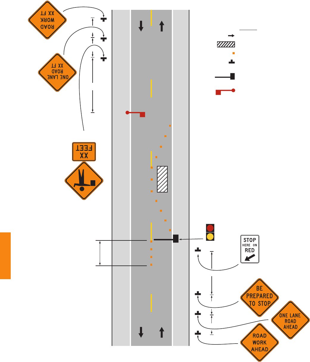
Page 572 2009 Edition
Figure 6E-2. Example of the Use of a Red/Yellow Lens Automated
Flagger Assistance Device (AFAD)
B
Channelizing
devices on
center line
(optional)
Note: Shown as Method 2 with
one AFAD and a flagger
(optional)
Note: See Table 6H-3 for the values
of A, B, and C dimensions
C
A
A
B
C
R
Y
Direction of travel
Work space
Channelizing device
Sign
AFAD with
recommended gate and
two-section signal face
Flagger
Legend
Sect. 6E.06 December 2009

2009 Edition Page 573
08 A change interval shall be provided as the transition between the display of the ashing CIRCULAR
YELLOW indication and the display of the steady CIRCULAR RED indication. During the change
interval, the CIRCULAR YELLOW lens shall be steadily illuminated. The gate arm shall remain in the
upright position during the display of the steadily illuminated CIRCULAR YELLOW change interval.
09 A change interval shall not be provided between the display of the steady CIRCULAR RED indication
and the display of the ashing CIRCULAR YELLOW indication.
Guidance:
10 The steadily illuminated CIRCULAR YELLOW change interval should have a duration of at least 5 seconds,
unless a different duration, within the range of durations recommended by Section 4D.26, is justied by
engineering judgment.
Section 6E.07 Flagger Procedures
Support:
01 The use of paddles and ags by aggers is illustrated in Figure 6E-3.
Standard:
02 Flaggers shall use a STOP/SLOW paddle, a ag, or an Automated Flagger Assistance Device (AFAD)
to control road users approaching a TTC zone. The use of hand movements alone without a paddle, ag,
or AFAD to control road users shall be prohibited except for law enforcement personnel or emergency
responders at incident scenes as described in Section 6I.01.
03 The following methods of signaling with paddles shall be used:
A. To stop road users, the agger shall face road users and aim the STOP paddle face toward road
users in a stationary position with the arm extended horizontally away from the body. The free arm
shall be held with the palm of the hand above shoulder level toward approaching trafc.
B. To direct stopped road users to proceed, the agger shall face road users with the SLOW paddle
face aimed toward road users in a stationary position with the arm extended horizontally away from
the body. The agger shall motion with the free hand for road users to proceed.
C. To alert or slow trafc, the agger shall face road users with the SLOW paddle face aimed toward
road users in a stationary position with the arm extended horizontally away from the body.
Option:
04 To further alert or slow trafc, the agger holding the SLOW paddle face toward road users may motion up
and down with the free hand, palm down.
Standard:
05 The following methods of signaling with a ag shall be used:
A. To stop road users, the agger shall face road users and extend the ag staff horizontally across
the road users’ lane in a stationary position so that the full area of the ag is visibly hanging
below the staff. The free arm shall be held with the palm of the hand above shoulder level toward
approaching trafc.
B. To direct stopped road users to proceed, the agger shall face road users with the ag and arm
lowered from the view of the road users, and shall motion with the free hand for road users to
proceed. Flags shall not be used to signal road users to proceed.
C. To alert or slow trafc, the agger shall face road users and slowly wave the ag in a sweeping
motion of the extended arm from shoulder level to straight down without raising the arm above a
horizontal position. The agger shall keep the free hand down.
Guidance:
06 The agger should stand either on the shoulder adjacent to the road user being controlled or in the closed
lane prior to stopping road users. A agger should only stand in the lane being used by moving road users after
road users have stopped. The agger should be clearly visible to the rst approaching road user at all times.
The agger also should be visible to other road users. The agger should be stationed sufciently in advance of
the workers to warn them (for example, with audible warning devices such as horns or whistles) of approaching
danger by out-of-control vehicles. The agger should stand alone, away from other workers, work vehicles,
or equipment.
Option:
07 At spot lane closures where adequate sight distance is available for the reasonably safe handling of trafc, the
use of one agger may be sufcient.
December 2009 Sect. 6E.06 to 6E.07
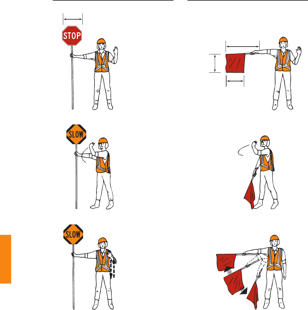
Page 574 2009 Edition
36 inches
24 inches
24
inches
18 inches
MIN.
TO STOP TRAFFIC
PREFERRED METHOD
STOP/SLOW Paddle
EMERGENCY SITUATIONS ONLY
Red Flag
TO LET
TRAFFIC PROCEED
TO ALERT AND
SLOW TRAFFIC
Figure 6E-3. Use of Hand-Signaling Devices by Flaggers
R1-1
W20-8
W20-8
Sect. 6E.07 December 2009

2009 Edition Page 575
Guidance:
08 When a single agger is used, the agger should be stationed on the shoulder opposite the spot lane closure
or work space, or in a position where good visibility and trafc control can be maintained at all times.
Section 6E.08 Flagger Stations
Standard:
01 Flagger stations shall be located such that approaching road users will have sufcient distance to stop at
an intended stopping point.
Option:
02 The distances shown in Table 6E-1, which provides
information regarding the stopping sight distance as a function
of speed, may be used for the location of a agger station.
These distances may be increased for downgrades and other
conditions that affect stopping distance.
Guidance:
03 Flagger stations should be located such that an errant
vehicle has additional space to stop without entering the work
space. The agger should identify an escape route that can be
used to avoid being struck by an errant vehicle.
Standard:
04 Except in emergency situations, agger stations
shall be preceded by an advance warning sign or signs.
Except in emergency situations, agger stations shall be
illuminated at night.
Table 6E-1. Stopping Sight Distance
as a Function of Speed
Speed* Distance
20 mph 115 feet
25 mph 155 feet
30 mph 200 feet
35 mph 250 feet
40 mph 305 feet
45 mph 360 feet
50 mph 425 feet
55 mph 495 feet
60 mph 570 feet
65 mph 645 feet
70 mph 730 feet
75 mph 820 feet
* Posted speed, off-peak 85th-percentile
speed prior to work starting, or the
anticipated operating speed
December 2009 Sect. 6E.07 to 6E.08

Page 576 2009 Edition
CHAPTER 6F. TEMPORARY TRAFFIC CONTROL ZONE DEVICES
Section 6F.01 Types of Devices
Guidance:
01 The design and application of TTC devices used in TTC zones should consider the needs of all road users
(motorists, bicyclists, and pedestrians), including those with disabilities.
Support:
02 FHWA policy requires that all roadside appurtenances such as trafc barriers, barrier terminals and crash
cushions, bridge railings, sign and light pole supports, and work zone hardware used on the National Highway
System meet the crashworthy performance criteria contained in the National Cooperative Highway Research
Program (NCHRP) Report 350, “Recommended Procedures for the Safety Performance Evaluation of Highway
Features.” The FHWA website at “http://safety.fhwa.dot.gov/programs/roadside_hardware.htm” identies all such
hardware and includes copies of FHWA acceptance letters for each of them. In the case of proprietary items, links
are provided to manufacturers’ websites as a source of detailed information on specic devices. The website also
contains an “Ask the Experts” section where questions on roadside design issues can be addressed.
03 Various Sections of the MUTCD require certain trafc control devices, their supports, and/or related
appurtenances to be crashworthy. Such MUTCD crashworthiness provisions apply to all streets, highways, and
private roads open to public travel. Also, State Departments of Transportation and local agencies might have
expanded the NCHRP Report 350 crashworthy criteria to apply to certain other roadside appurtenances.
04 Crashworthiness and crash testing information on devices described in Part 6 are found in AASHTO’s
“Roadside Design Guide” (see Section 1A.11).
05 As dened in Section 1A.13, “crashworthy” is a characteristic of a roadside appurtenance that has been
successfully crash tested in accordance with a national standard such as the NCHRP Report 350, “Recommended
Procedures for the Safety Performance Evaluation of Highway Features.”
Standard:
06 Trafc control devices shall be dened as all signs, signals, markings, and other devices used to
regulate, warn, or guide road users, placed on, over, or adjacent to a street, highway, private roads open to
public travel (see denition in Section 1A.13), pedestrian facility, or bikeway by authority of a public body
or ofcial having jurisdiction.
07 All trafc control devices used for construction, maintenance, utility, or incident management
operations on a street, highway, or private road open to public travel (see denition in Section 1A.13) shall
comply with the applicable provisions of this Manual.
Section 6F.02 General Characteristics of Signs
Support:
01 TTC zone signs convey both general and specic messages by means of words, symbols, and/or arrows and
have the same three categories as all road user signs: regulatory, warning, and guide.
Standard:
02 The colors for regulatory signs shall follow the Standards for regulatory signs in Table 2A-5 and
Chapter 2B. Warning signs in TTC zones shall have a black legend and border on an orange background,
except for the Grade Crossing Advance Warning (W10-1) sign which shall have a black legend and border
on a yellow background, and except for signs that are required or recommended in Parts 2 or 7 to have
uorescent yellow-green backgrounds. Colors for guide signs shall follow the Standards in Table 2A-5
and Chapter 2D, except for guide signs as otherwise provided in Section 6F.55.
Option:
03 Where the color orange is required, the uorescent orange color may also be used.
Support:
04 The uorescent version of orange provides higher conspicuity than standard orange, especially during twilight.
Option:
05 Existing warning signs that are still applicable may remain in place.
06 In order to maintain the systematic use of yellow or uorescent yellow-green backgrounds for pedestrian,
bicycle, and school warning signs in a jurisdiction, the yellow or uorescent yellow-green background for
pedestrian, bicycle, and school warning signs may be used in TTC zones.
07 Standard orange ags or ashing warning lights may be used in conjunction with signs.
Sect. 6F.01 to 6F.02 December 2009

2009 Edition Page 577
Standard:
08 When standard orange ags or ashing warning lights are used in conjunction with signs, they shall not
block the sign face.
09 Except as provided in Section 2A.11, the sizes for TTC signs and plaques shall be as shown in
Table 6F-1. The sizes in the minimum column shall only be used on local streets or roadways where the
85th-percentile speed or posted speed limit is less than 35 mph.
Option:
10 The dimensions of signs and plaques shown in Table 6F-1 may be increased wherever necessary for greater
legibility or emphasis.
Standard:
11 Deviations from standard sizes as prescribed in this Manual shall be in 6-inch increments.
Support:
12 Sign design details are contained in the “Standard Highway Signs and Markings” book (see Section 1A.11).
13 Section 2A.06 contains additional information regarding the design of signs, including an Option allowing the
development of special word message signs if a standard word message or symbol sign is not available to convey
the necessary regulatory, warning, or guidance information.
Standard:
14 All signs used at night shall be either retroreective with a material that has a smooth, sealed outer
surface or illuminated to show the same shape and similar color both day and night.
15 The requirement for sign illumination shall not be considered to be satised by street, highway, or
strobe lighting.
Option:
16 Sign illumination may be either internal or external.
17 Signs may be made of rigid or exible material.
Section 6F.03 Sign Placement
Guidance:
01 Signs should be located on the right-hand side of the roadway unless otherwise provided in this Manual.
Option:
02 Where special emphasis is needed, signs may be placed on both the left-hand and right-hand sides of the
roadway. Signs mounted on portable supports may be placed within the roadway itself. Signs may also be
mounted on or above barricades.
Support:
03 The provisions of this Section regarding mounting height apply unless otherwise provided for a particular sign
elsewhere in this Manual.
Standard:
04 The minimum height, measured vertically from the bottom of the sign to the elevation of the near edge
of the pavement, of signs installed at the side of the road in rural areas shall be 5 feet (see Figure 6F-1).
05 The minimum height, measured vertically from the bottom of the sign to the top of the curb, or in the
absence of curb, measured vertically from the bottom of the sign to the elevation of the near edge of the
traveled way, of signs installed at the side of the road in business, commercial, or residential areas where
parking or pedestrian movements are likely to occur, or where the view of the sign might be obstructed,
shall be 7 feet (see Figure 6F-1).
06 The minimum height, measured vertically from the bottom of the sign to the sidewalk, of signs installed
above sidewalks shall be 7 feet.
Option:
07 The height to the bottom of a secondary sign mounted below another sign may be 1 foot less than the height
provided in Paragraphs 4 through 6.
Guidance:
08 Neither portable nor permanent sign supports should be located on sidewalks, bicycle facilities, or areas
designated for pedestrian or bicycle trafc. If the bottom of a secondary sign that is mounted below another sign
is mounted lower than 7 feet above a pedestrian sidewalk or pathway (see Section 6D.02), the secondary sign
should not project more than 4 inches into the pedestrian facility.
December 2009 Sect. 6F.02 to 6F.03

Page 578 2009 Edition
Sign or Plaque
Sign
Designation
Section
Conventional
Road
Freeway or
Expressway
Minimum
Stop R1-1 6F.06 30 x 30* — —
Stop (on Stop/Slow Paddle) R1-1 6E.03 18 x 18 — —
Yield R1-2 6F.06 36 x 36 x 36* — 30 x 30 x 30
To Oncoming Traffic (plaque) R1-2aP 6F.06 36 x 30 48 x 36 24 x 18
Wait on Stop R1-7 6E.05 24 x 30 24 x 30 —
Go on Slow R1-8 6E.05 24 x 30 24 x 30 —
Speed Limit R2-1 6F.12 24 x 30* 36 x 48 —
Fines Higher (plaque) R2-6P 6F.12 24 x 18 36 x 24 —
Fines Double (plaque) R2-6aP 6F.12 24 x 18 36 x 24 —
$XX Fine (plaque) R2-6bP 6F.12 24 x 18 36 x 24 —
Begin Higher Fines Zone R2-10 6F.12 24 x 30 36 x 48 —
End Higher Fines Zone R2-11 6F.12 24 x 30 36 x 48 —
End Work Zone Speed Limit R2-12 6F.12 24 x 36 36 x 54 —
Movement Prohibition R3-1,2,3,4,18,27 6F.06 24 x 24* 36 x 36 —
Mandatory Movement (1 lane) R3-5 6F.06 30 x 36 — —
Optional Movement (1 lane) R3-6 6F.06 30 x 36 — —
Mandatory Movement (text) R3-7 6F.06 30 x 30* — —
Advance Intersection Lane Control R3-8 6F.06 Varies x 30 — —
Do Not Pass R4-1 6F.06 24 x 30 36 x 48 —
Pass With Care R4-2 6F.06 24 x 30 36 x 48 —
Keep Right R4-7 6F.06 24 x 30 36 x 48 —
Narrow Keep Right R4-7c 6F.06 18 x 30 — —
Stay in Lane R4-9 6F.11 24 x 30 36 x 48 —
Do Not Enter R5-1 6F.06 30 x 30* 36 x 36 —
Wrong Way R5-1a 6F.06 36 x 24* 42 x 30 —
One Way R6-1 6F.06 36 x 12* 54 x 18 —
One Way R6-2 6F.06 24 x 30* 36 x 48 —
No Parking (symbol) R8-3 6F.06 24 x 24 36 x 36 —
Pedestrian Crosswalk R9-8 6F.13 36 x 18 — —
Sidewalk Closed R9-9 6F.14 24 x 12 — —
Sidewalk Closed, Use Other Side R9-10 6F.14 24 x 12 — —
Sidewalk Closed Ahead, Cross Here R9-11 6F.14 24 x 18 — —
Sidewalk Closed, Cross Here R9-11a 6F.14 24 x 12 — —
Road Closed R11-2 6F.08 48 x 30 — —
Road Closed - Local Traffic Only R11-3a,3b,4 6F.09 60 x 30 — —
Weight Limit R12-1,2 6F.10 24 x 30 36 x 48 —
Weight Limit (with symbols) R12-5 6F.10 24 x 36 36 x 48 —
Turn and Curve Signs W1-1,2,3,4 6F.16 36 x 36 48 x 48 30 x 30
Reverse Curve (2 or more lanes) W1-4b,4c 6F.48 36 x 36 48 x 48 30 x 30
One-Direction Large Arrow W1-6 6F.16 48 x 24 60 x 30 —
Chevron W1-8 6F.16 18 x 24 30 x 36 —
Stop Ahead W3-1 6F.16 36 x 36 48 x 48 30 x 30
Yield Ahead W3-2 6F.16 36 x 36 48 x 48 30 x 30
Signal Ahead W3-3 6F.16 36 x 36 48 x 48 30 x 30
Be Prepared to Stop W3-4 6F.16 36 x 36 48 x 48 30 x 30
Reduced Speed Limit Ahead W3-5 6F.16 36 x 36 48 x 48 30 x 30
Table 6F-1. Temporary Traffic Control Zone Sign and Plaque Sizes (Sheet 1 of 3)
Sect. 6F.03 December 2009

2009 Edition Page 579
Sign or Plaque
Sign
Designation
Section
Conventional
Road
Freeway or
Expressway
Minimum
XX MPH Speed Zone Ahead W3-5a 6F.16 36 x 36 48 x 48 30 x 30
Merging Traffic W4-1,5 6F.16 36 x 36 48 x 48 36 x 36
Lane Ends W4-2 6F.24 36 x 36 48 x 48 30 x 30
Added Lane W4-3,6 6F.16 36 x 36 48 x 48 30 x 30
No Merge Area (plaque) W4-5P 6F.16 18 x 24 24 x 30 —
Road Narrows W5-1 6F.16 36 x 36 48 x 48 30 x 30
Narrow Bridge W5-2 6F.16 36 x 36 48 x 48 30 x 30
One Lane Bridge W5-3 6F.16 36 x 36 48 x 48 30 x 30
Ramp Narrows W5-4 6F.26 36 x 36 48 x 48 30 x 30
Divided Highway W6-1 6F.16 36 x 36 48 x 48 30 x 30
Divided Highway Ends W6-2 6F.16 36 x 36 48 x 48 30 x 30
Two-Way Traffic W6-3 6F.32 36 x 36 48 x 48 30 x 30
Two-Way Traffic W6-4 6F.76 12 x 18 12 x 18 —
Hill (symbol) W7-1 6F.16 36 x 36 48 x 48 30 x 30
Next XX Miles (plaque) W7-3aP 6F.53 24 x 18 36 x 30 —
Bump W8-1 6F.16 36 x 36 48 x 48 30 x 30
Dip W8-2 6F.16 36 x 36 48 x 48 30 x 30
Pavement Ends W8-3 6F.16 36 x 36 48 x 48 30 x 30
Soft Shoulder W8-4 6F.44 36 x 36 48 x 48 30 x 30
Slippery When Wet W8-5 6F.16 36 x 36 48 x 48 30 x 30
Truck Crossing W8-6 6F.36 36 x 36 48 x 48 30 x 30
Loose Gravel W8-7 6F.16 36 x 36 48 x 48 30 x 30
Rough Road W8-8 6F.16 36 x 36 48 x 48 30 x 30
Low Shoulder W8-9 6F.44 36 x 36 48 x 48 30 x 30
Uneven Lanes W8-11 6F.45 36 x 36 48 x 48 30 x 30
No Center Line W8-12 6F.47 36 x 36 48 x 48 30 x 30
Fallen Rocks W8-14 6F.16 36 x 36 48 x 48 30 x 30
Grooved Pavement W8-15 6F.16 36 x 36 48 x 48 30 x 30
Motorcycle (plaque) W8-15P 6F.54 24 x 18 30 x 24 —
Shoulder Drop Off (symbol) W8-17 6F.44 36 x 36 48 x 48 30 x 30
Shoulder Drop-Off (plaque) W8-17P 6F.44 24 x 18 30 x 24 —
Road May Flood W8-18 6F.16 36 x 36 48 x 48 24 x 24
No Shoulder W8-23 6F.16 36 x 36 48 x 48 30 x 30
Steel Plate Ahead W8-24 6F.46 36 x 36 48 x 48 30 x 30
Shoulder Ends W8-25 6F.16 36 x 36 48 x 48 30 x 30
Lane Ends W9-1,2 6F.16 36 x 36 48 x 48 30 x 30
Center Lane Closed Ahead W9-3 6F.23 36 x 36 48 x 48 30 x 30
Grade Crossing Advance Warning W10-1 6F.16 36 dia. — —
Truck W11-10 6F.36 36 x 36 48 x 48 30 x 30
Double Arrow W12-1 6F.16 30 x 30 — —
Low Clearance W12-2 6F.16 36 x 36 48 x 48 30 x 30
Advisory Speed (plaque) W13-1P 6F.52 24 x 24 30 x 30 18 x 18
On Ramp (plaque) W13-4P 6F.25 36 x 36 36 x 36 —
No Passing Zone (pennant) W14-3 6F.16 48 x 48 x 36 64 x 64 x 48 40 x 40 x 30
XX Feet (plaque) W16-2P 6F.16 24 x 18 30 x 24 —
Road Work (with distance) W20-1 6F.18 36 x 36 48 x 48 30 x 30
Table 6F-1. Temporary Traffic Control Zone Sign and Plaque Sizes (Sheet 2 of 3)
December 2009 Sect. 6F.03

Page 580 2009 Edition
Sign or Plaque
Sign
Designation
Section
Conventional
Road
Freeway or
Expressway
Minimum
Detour (with distance) W20-2 6F.19 36 x 36 48 x 48 30 x 30
Road (Street) Closed (with distance) W20-3 6F.20 36 x 36 48 x 48 30 x 30
One Lane Road (with distance) W20-4 6F.21 36 x 36 48 x 48 30 x 30
Lane(s) Closed (with distance) W20-5,5a 6F.22 36 x 36 48 x 48 30 x 30
Flagger (symbol) W20-7 6F.31 36 x 36 48 x 48 30 x 30
Flagger W20-7a 6F.31 36 x 36 48 x 48 30 x 30
Slow (on Stop/Slow Paddle) W20-8 6E.03 18 x 18 — —
Workers W21-1,1a 6F.33 36 x 36 48 x 48 30 x 30
Fresh Oil (Tar) W21-2 6F.34 36 x 36 48 x 48 30 x 30
Road Machinery Ahead W21-3 6F.35 36 x 36 48 x 48 30 x 30
Slow Moving Vehicle W21-4 6G.06 36 x 18 — —
Shoulder Work W21-5 6F.37 36 x 36 48 x 48 30 x 30
Shoulder Closed W21-5a 6F.37 36 x 36 48 x 48 30 x 30
Shoulder Closed (with distance) W21-5b 6F.37 36 x 36 48 x 48 30 x 30
Survey Crew W21-6 6F.38 36 x 36 48 x 48 30 x 30
Utility Work Ahead W21-7 6F.39 36 x 36 48 x 48 30 x 30
Mowing Ahead W21-8 6G.06 36 x 36 48 x 48 30 x 30
Blasting Zone Ahead W22-1 6F.41 36 x 36 48 x 48 30 x 30
Turn Off 2-Way Radio and Cell
Phone
W22-2 6F.42 42 x 36 42 x 36 —
End Blasting Zone W22-3 6F.43 42 x 36 42 x 36 36 x 30
Slow Traffic Ahead W23-1 6F.27 48 x 24 48 x 24 —
New Traffic Pattern Ahead W23-2 6F.30 36 x 36 48 x 48 30 x 30
Double Reverse Curve (1 lane) W24-1 6F.49 36 x 36 48 x 48 30 x 30
Double Reverse Curve (2 lanes) W24-1a 6F.49 36 x 36 48 x 48 30 x 30
Double Reverse Curve (3 lanes) W24-1b 6F.49 36 x 36 48 x 48 30 x 30
All Lanes W24-1cP 6F.49 24 x 24 30 x 30 —
Road Work Next XX Miles G20-1 6F.56 36 x 18 48 x 24 —
End Road Work G20-2 6F.57 36 x 18 48 x 24 —
Pilot Car Follow Me G20-4 6F.58 36 x 18 — —
Work Zone (plaque) G20-5aP 6F.12 24 x 18 36 x 24 —
Exit Open E5-2 6F.28 48 x 36 48 x 36 —
Exit Closed E5-2a 6F.28 48 x 36 48 x 36 —
Exit Only E5-3 6F.29 48 x 36 48 x 36 —
Detour M4-8 6F.59 24 x 12 30 x 15 —
End Detour M4-8a 6F.59 24 x 18 24 x 18 —
End M4-8b 6F.59 24 x 12 24 x 12 —
Detour M4-9 6F.59 30 x 24 48 x 36 —
Bike/Pedestrian Detour M4-9a 6F.59 30 x 24 — —
Pedestrian Detour M4-9b 6F.59 30 x 24 — —
Bike Detour M4-9c 6F.59 30 x 24 — —
Detour M4-10 6F.59 48 x 18 — —
* See Table 2B-1 for minimum size required for signs facing traffic on multi-lane conventional roads
Notes: 1. Larger signs may be used wherever necessary for greater legibility or emphasis
2. Dimensions are shown in inches and are shown as width x height
Table 6F-1. Temporary Traffic Control Zone Sign and Plaque Sizes (Sheet 3 of 3)
Sect. 6F.03 December 2009

2009 Edition Page 581
Standard:
09 Where it has been determined that the accommodation of pedestrians with disabilities is necessary,
signs shall be mounted and placed in accordance with Section 4.4 of the “Americans with Disabilities Act
Accessibility Guidelines for Buildings and Facilities (ADAAG)” (see Section 1A.11).
10 Signs mounted on barricades and barricade/sign combinations shall be crashworthy.
Guidance:
11 Except as provided in Paragraph 12, signs mounted on portable sign supports that do not meet the minimum
mounting heights provided in Paragraphs 4 through 6 should not be used for a duration of more than 3 days.
Option:
12 The R9-8 through R9-11a series, R11 series, W1-6 through W1-8 series, M4-10, E5-1, or other similar type
signs (see Figures 6F-3, 6F-4, and 6F-5) may be used on portable sign supports that do not meet the minimum
mounting heights provided in Paragraphs 4 through 6 for longer than 3 days.
Support:
13 Methods of mounting signs other than on posts are illustrated in Figure 6F-2.
Guidance:
14 Signs mounted on Type 3 Barricades should not cover more than 50 percent of the top two rails or 33 percent
of the total area of the three rails.
Standard:
15 Sign supports shall be crashworthy. Where large signs having an area exceeding 50 square feet are
installed on multiple breakaway posts, the clearance from the ground to the bottom of the sign shall be at
least 7 feet.
C - BUSINESS, COMMERCIAL,
OR RESIDENTIAL AREA
Walkway
2 ft
MIN.
7 ft
MIN.
D - BUSINESS, COMMERCIAL, OR RESIDENTIAL
AREA (WITHOUT CURB)
6 to 12 ft
7 ft
MIN.
6 to 12 ft
6 ft MIN.
4 ft
MIN.
Paved shoulder
B - RURAL AREA WITH ADVISORY SPEED PLAQUE
6 to 12 ft
A - RURAL AREA
5 ft MIN.
Figure 6F-1. Height and Lateral Location of Signs—Typical Installations
December 2009 Sect. 6F.03

Page 582 2009 Edition
1 ft MIN. above
the traveled way
1 ft MIN.
above the traveled way
8 ft MIN.
(see Section 6F.62)
Orange Flag
(optional)
High-Level Warning Device
(Flag Tree)
PORTABLE AND TEMPORARY MOUNTINGS
Flasher
(optional)
BARRICADES
Figure 6F-2. Methods of Mounting Signs Other Than on Posts
Sect. 6F.03 December 2009

2009 Edition Page 583
16 The bottom of a sign mounted on a barricade, or other portable support, shall be at least 1 foot above
the traveled way.
Option:
17 For mobile operations, a sign may be mounted on a work vehicle, a shadow vehicle, or a trailer stationed in
advance of the TTC zone or moving along with it.
Support:
18 If alterations are made to specic trafc control device supports that have been successfully crash tested in
accordance with NCHRP Report 350, the altered supports might not be considered to be crashworthy.
Section 6F.04 Sign Maintenance
Guidance:
01 Signs should be properly maintained for cleanliness, visibility, and correct positioning.
02 Signs that have lost signicant legibility should be promptly replaced.
Support:
03 Section 2A.08 contains information regarding the retroreectivity of signs, including the signs that are used
in TTC zones.
Section 6F.05 Regulatory Sign Authority
Support:
01 Regulatory signs such as those shown in Figure 6F-3 inform road users of trafc laws or regulations and
indicate the applicability of legal requirements that would not otherwise be apparent.
Standard:
02 Regulatory signs shall be authorized by the public agency or ofcial having jurisdiction and shall
conform with Chapter 2B.
Section 6F.06 Regulatory Sign Design
Standard:
01 TTC regulatory signs shall comply with the Standards for regulatory signs presented in Part 2 and in
the FHWA’s “Standard Highway Signs and Markings” book (see Section 1A.11).
Support:
02 Regulatory signs are generally rectangular with a black legend and border on a white background. Exceptions
include the STOP, YIELD, DO NOT ENTER, WRONG WAY, and ONE WAY signs.
Option:
03 The ONE WAY sign may be either a horizontal or vertical rectangular sign.
Section 6F.07 Regulatory Sign Applications
Standard:
01 If a TTC zone requires regulatory measures different from those existing, the existing permanent
regulatory devices shall be removed or covered and superseded by the appropriate temporary regulatory
signs. This change shall be made in compliance with applicable ordinances or statutes of the jurisdiction.
Section 6F.08 ROAD (STREET) CLOSED Sign (R11-2)
Guidance:
01 The ROAD (STREET) CLOSED (R11-2) sign (see Figure 6F-3) should be used when the roadway is closed
to all road users except contractors’ equipment or ofcially authorized vehicles. The R11-2 sign should be
accompanied by appropriate warning and detour signing.
Option:
02 The words BRIDGE OUT (or BRIDGE CLOSED) may be substituted for ROAD (STREET) CLOSED
where applicable.
Guidance:
03 The ROAD (STREET) CLOSED sign should be installed at or near the center of the roadway on or above
a Type 3 Barricade that closes the roadway (see Section 6F.68).
December 2009 Sect. 6F.03 to 6F.08

Page 584 2009 Edition
R1-1 R1-2
R3-3R3-2R3-1
R3-5
R1-2aP
Figure 6F-3. Regulatory Signs and Plaques in Temporary Traffic Control Zones
(Sheet 1 of 2)
R3-4
R2-10
R2-11
R2-12
R4-2 R4-7
R6-2
R8-3 R9-8
R4-9 R5-1
R5-1a R6-1
R3-6
R3-7
R3-18
R3-8
R4-7cR4-1
R1-7 R1-8
R3-27
G20-5aP
R2-6aP R2-6bPR2-6PR2-1
Sect. 6F.08 December 2009

2009 Edition Page 585
Standard:
04 The ROAD (STREET) CLOSED sign shall not be used where road user ow is maintained through
the TTC zone with a reduced number of lanes on the existing roadway or where the actual closure is some
distance beyond the sign.
Section 6F.09 Local Trafc Only Signs (R11-3a, R11-4)
Guidance:
01 The Local Trafc Only signs (see Figure 6F-3) should be used where road user ow detours to avoid a closure
some distance beyond the sign, but where local road users can use the roadway to the point of closure. These
signs should be accompanied by appropriate warning and detour signing.
02 In rural applications, the Local Trafc Only sign should have the legend ROAD CLOSED XX MILES
AHEAD, LOCAL TRAFFIC ONLY (R11-3a).
Option:
03 In urban areas, the legend ROAD (STREET) CLOSED TO THRU TRAFFIC (R11-4) or ROAD CLOSED,
LOCAL TRAFFIC ONLY may be used.
04 In urban areas, a word message that includes the name of an intersecting street name or well-known
destination may be substituted for the words XX MILES AHEAD on the R11-3a sign where applicable.
05 The words BRIDGE OUT (or BRIDGE CLOSED) may be substituted for the words ROAD (STREET)
CLOSED on the R11-3a or R11-4 sign where applicable.
Section 6F.10 Weight Limit Signs (R12-1, R12-2, R12-5)
Standard:
01 A Weight Limit sign (see Figure 6F-3), which shows the gross weight or axle weight that is permitted on
the roadway or bridge, shall be consistent with State or local regulations and shall not be installed without
the approval of the authority having jurisdiction over the highway.
02 When weight restrictions are imposed because of the activity in a TTC zone, a marked detour shall be
provided for vehicles weighing more than the posted limit.
R11-3a R11-3b R11-4
R9-9 R9-10 R11-2R9-11 R9-11a
Figure 6F-3. Regulatory Signs and Plaques in Temporary Traffic Control Zones
(Sheet 2 of 2)
R12-1 R12-2 R12-5
December 2009 Sect. 6F.08 to 6F.10

Page 586 2009 Edition
Section 6F.11 STAY IN LANE Sign (R4-9)
Option:
01 A STAY IN LANE (R4-9) sign (see Figure 6F-3) may be used where a multi-lane shift has been incorporated
as part of the TTC on a highway to direct road users around road work that occupies part of the roadway on a
multi-lane highway.
Section 6F.12 Work Zone and Higher Fines Signs and Plaques
Option:
01 A WORK ZONE (G20-5aP) plaque (see Figure 6F-3) may be mounted above a Speed Limit sign to emphasize
that a reduced speed limit is in effect within a TTC zone. An END WORK ZONE SPEED LIMIT (R2-12) sign
(see Figure 6F-3) may be installed at the downstream end of the reduced speed limit zone.
Guidance:
02 A BEGIN HIGHER FINES ZONE (R2-10) sign (see Figure 6F-3) should be installed at the upstream end of a
work zone where increased nes are imposed for trafc violations, and an END HIGHER FINES ZONE (R2-11)
sign (see Figure 6F-3) should be installed at the downstream end of the work zone.
Option:
03 Alternate legends such as BEGIN (or END) DOUBLE FINES ZONE may also be used for the R2-10 and
R2-11 signs.
04 A FINES HIGHER, FINES DOUBLE, or $XX FINE plaque (see Section 2B.17 and Figure 6F-3) may be
mounted below the Speed Limit sign if increased nes are imposed for trafc violations within the TTC zone.
05 Individual signs and plaques for work zone speed limits and higher nes may be combined into a single sign
or may be displayed as an assembly of signs and plaques.
Section 6F.13 PEDESTRIAN CROSSWALK Sign (R9-8)
Option:
01 The PEDESTRIAN CROSSWALK (R9-8) sign (see Figure 6F-3) may be used to indicate where a temporary
crosswalk has been established.
Standard:
02 If a temporary crosswalk is established, it shall be accessible to pedestrians with disabilities in
accordance with Section 6D.02.
Section 6F.14 SIDEWALK CLOSED Signs (R9-9, R9-10, R9-11, R9-11a)
Guidance:
01 SIDEWALK CLOSED signs (see Figure 6F-3) should be used where pedestrian ow is restricted.
Bicycle/Pedestrian Detour (M4-9a) signs or Pedestrian Detour (M4-9b) signs should be used where pedestrian
ow is rerouted (see Section 6F.59).
02 The SIDEWALK CLOSED (R9-9) sign should be installed at the beginning of the closed sidewalk, at the
intersections preceding the closed sidewalk, and elsewhere along the closed sidewalk as needed.
03 The SIDEWALK CLOSED, (ARROW) USE OTHER SIDE (R9-10) sign should be installed at the beginning
of the restricted sidewalk when a parallel sidewalk exists on the other side of the roadway.
04 The SIDEWALK CLOSED AHEAD, (ARROW) CROSS HERE (R9-11) sign should be used to indicate to
pedestrians that sidewalks beyond the sign are closed and to direct them to open crosswalks, sidewalks, or other
travel paths.
05 The SIDEWALK CLOSED, (ARROW) CROSS HERE (R9-11a) sign should be installed just beyond the point
to which pedestrians are being redirected.
Support:
06 These signs are typically mounted on a detectable barricade to encourage compliance and to communicate
with pedestrians that the sidewalk is closed. Printed signs are not useful to many pedestrians with visual
disabilities. A barrier or barricade detectable by a person with a visual disability is sufcient to indicate that
a sidewalk is closed. If the barrier is continuous with detectable channelizing devices for an alternate route,
accessible signing might not be necessary. An audible information device is needed when the detectable barricade
or barrier for an alternate channelized route is not continuous.
Sect. 6F.11 to 6F.14 December 2009

2009 Edition Page 587
Section 6F.15 Special Regulatory Signs
Option:
01 Special regulatory signs may be used based on engineering judgment consistent with regulatory requirements.
Guidance:
02 Special regulatory signs should comply with the general requirements of color, shape, and alphabet size and
series. The sign message should be brief, legible, and clear.
Section 6F.16 Warning Sign Function, Design, and Application
Support:
01 TTC zone warning signs (see Figure 6F-4) notify road users of specic situations or conditions on or adjacent
to a roadway that might not otherwise be apparent.
Standard:
02 TTC warning signs shall comply with the Standards for warning signs presented in Part 2 and
in FHWA’s “Standard Highway Signs and Markings” book (see Section 1A.11). Except as provided
in Paragraph 3, TTC warning signs shall be diamond-shaped with a black legend and border on an
orange background, except for the W10-1 sign which shall have a black legend and border on a yellow
background, and except for signs that are required or recommended in Parts 2 or 7 to have uorescent
yellow-green backgrounds.
Option:
03 Warning signs used for TTC incident management situations may have a black legend and border on a
uorescent pink background.
04 Mounting or space considerations may justify a change from the standard diamond shape.
05 In emergencies, available warning signs having yellow backgrounds may be used if signs with orange or
uorescent pink backgrounds are not at hand.
Guidance:
06 Where roadway or road user conditions require greater emphasis, larger than standard size warning signs
should be used, with the symbol or legend enlarged approximately in proportion to the outside dimensions.
07 Where any part of the roadway is obstructed or closed by work activities or incidents, advance warning signs
should be installed to alert road users well in advance of these obstructions or restrictions.
08 Where road users include pedestrians, the provision of supplemental audible information or
detectable barriers or barricades should be considered for people with visual disabilities.
Support:
09 Detectable barriers or barricades communicate very clearly to pedestrians who have visual disabilities that
they can no longer proceed in the direction that they are traveling.
Option:
10 Advance warning signs may be used singly or in combination.
11 Where distances are not displayed on warning signs as part of the message, a supplemental plaque with the
distance legend may be mounted immediately below the sign on the same support.
Section 6F.17 Position of Advance Warning Signs
Guidance:
01 Where highway conditions permit, warning signs should be placed in advance of the TTC zone at varying
distances depending on roadway type, condition, and posted speed. Table 6C-1 contains information regarding
the spacing of advance warning signs. Where a series of two or more advance warning signs is used, the closest
sign to the TTC zone should be placed approximately 100 feet for low-speed urban streets to 1,000 feet or more
for freeways and expressways.
02 Where multiple advance warning signs are needed on the approach to a TTC zone, the ROAD WORK
AHEAD (W20-1) sign should be the rst advance warning sign encountered by road users.
Support:
03 Various conditions, such as limited sight distance or obstructions that might require a driver to reduce speed or
stop, might require additional advance warning signs.
Option:
04 As an alternative to a specic distance on advance warning signs, the word AHEAD may be used.
December 2009 Sect. 6F.15 to 6F.17

Page 588 2009 Edition
W1-1 W1-2 W1-3 W1-4 W1-4b
W6-2
W3-1W1-8W1-4c W3-2W1-6
Figure 6F-4. Warning Signs and Plaques in Temporary Traffic Control Zones
(Sheet 1 of 3)
W3-3 W3-4 W3-5 W3-5a W4-1
W4-3 W4-5 W4-5PW4-2 W4-6
W5-4W5-1 W5-2 W5-3 W6-1
W6-3
W6-4 W7-1 W8-1
W7-3aP
Sect. 6F.17 December 2009

2009 Edition Page 589
W8-12
W8-17
W8-17P
Figure 6F-4. Warning Signs and Plaques in Temporary Traffic Control Zones
(Sheet 2 of 3)
W8-2 W8-3 W8-4 W8-5 W8-6 W8-7
W8-8 W8-9 W8-11
W9-2W9-1
W8-23
W8-15
W8-15P
W8-18
W8-25
W8-14
W8-24 W9-3
W12-1 W12-2 W11-10 W13-4PW13-1P
December 2009 Sect. 6F.17

Page 590 2009 Edition
Figure 6F-4. Warning Signs and Plaques in Temporary Traffic Control Zones (Sheet 3 of 3)
* An optional STREET WORK word message sign is shown in the “Standard Highway Signs and Markings” book.
** An optional STREET CLOSED word message sign is shown in the “Standard Highway Signs and Markings” book.
*** An optional FLAGGER (W20-7a) word message sign is shown in the “Standard Highway Signs and Markings” book.
**** An optional FRESH TAR word message sign is show in the “Standard Highway Signs and Markings” book.
G20-2
G20-4
G20-1
W21-6W21-5bW21-5 W21-5aW21-3 W21-4
W21-7 W22-1 W22-3W22-2W21-8
W20-5 W20-5a W21-1 W21-2****W16-2P
W20-7***
W24-1b
W23-1 W24-1aW23-2
W24-1
W24-1cP
W20-3** W20-4W14-3 W20-1* W20-2
Sect. 6F.17 December 2009

2009 Edition Page 591
Support:
05 At TTC zones on lightly-traveled roads, all of the advance warning signs prescribed for major construction
might not be needed.
Option:
06 Utility work, maintenance, or minor construction can occur within the TTC zone limits of a major
construction project, and additional warning signs may be needed.
Guidance:
07 Utility, maintenance, and minor construction signing and TTC should be coordinated with appropriate
authorities so that road users are not confused or misled by the additional TTC devices.
Section 6F.18 ROAD (STREET) WORK Sign (W20-1)
Guidance:
01 The ROAD (STREET) WORK (W20-1) sign (see Figure 6F-4), which serves as a general warning of
obstructions or restrictions, should be located in advance of the work space or any detour, on the road where the
work is taking place.
02 Where trafc can enter a TTC zone from a crossroad or a major (high-volume) driveway, an advance
warning sign should be used on the crossroad or major driveway.
Standard:
03 The ROAD (STREET) WORK (W20-1) sign shall have the legend ROAD (STREET) WORK,
XX FEET, XX MILES, or AHEAD.
Section 6F.19 DETOUR Sign (W20-2)
Guidance:
01 The DETOUR (W20-2) sign (see Figure 6F-4) should be used in advance of a road user detour over a
different roadway or route.
Standard:
02 The DETOUR sign shall have the legend DETOUR, XX FEET, XX MILES, or AHEAD.
Section 6F.20 ROAD (STREET) CLOSED Sign (W20-3)
Guidance:
01 The ROAD (STREET) CLOSED (W20-3) sign (see Figure 6F-4) should be used in advance of the point where
a highway is closed to all road users, or to all but local road users.
Standard:
02 The ROAD (STREET) CLOSED sign shall have the legend ROAD (STREET) CLOSED, XX FEET, XX
MILES, or AHEAD.
Section 6F.21 ONE LANE ROAD Sign (W20-4)
Standard:
01 The ONE LANE ROAD (W20-4) sign (see Figure 6F-4) shall be used only in advance of that point
where motor vehicle trafc in both directions must use a common single lane (see Section 6C.10). It shall
have the legend ONE LANE ROAD, XX FEET, XX MILES, or AHEAD.
Section 6F.22 Lane(s) Closed Signs (W20-5, W20-5a)
Standard:
01 The Lane(s) Closed sign (see Figure 6F-4) shall be used in advance of that point where one or more
through lanes of a multi-lane roadway are closed.
02 For a single lane closure, the Lane Closed (W20-5) sign (see Figure 6F-4) shall have the legend RIGHT
(LEFT) LANE CLOSED, XX FEET, XX MILES, or AHEAD. Where two adjacent lanes are closed, the
W20-5a sign (see Figure 6F-4) shall have the legend XX RIGHT (LEFT) LANES CLOSED, XX FEET,
XX MILES, or AHEAD.
December 2009 Sect. 6F.17 to 6F.22

Page 592 2009 Edition
Section 6F.23 CENTER LANE CLOSED AHEAD Sign (W9-3)
Guidance:
01 The CENTER LANE CLOSED AHEAD (W9-3) sign (see Figure 6F-4) should be used in advance of that point
where work occupies the center lane(s) and approaching motor vehicle trafc is directed to the right or left of the
work zone in the center lane.
Section 6F.24 Lane Ends Sign (W4-2)
Option:
01 The Lane Ends (W4-2) symbol sign (see Figure 6F-4) may be used to warn drivers of the reduction in the
number of lanes for moving motor vehicle trafc in the direction of travel on a multi-lane roadway.
Section 6F.25 ON RAMP Plaque (W13-4P)
Guidance:
01 When work is being done on a ramp, but the ramp remains open, the ON RAMP (W13-4P) plaque
(see Figure 6F-4) should be used to supplement the advance ROAD WORK sign.
Section 6F.26 RAMP NARROWS Sign (W5-4)
Guidance:
01 The RAMP NARROWS (W5-4) sign (see Figure 6F-4) should be used in advance of the point where work on a
ramp reduces the normal width of the ramp along a part or all of the ramp.
Section 6F.27 SLOW TRAFFIC AHEAD Sign (W23-1)
Option:
01 The SLOW TRAFFIC AHEAD (W23-1) sign (see Figure 6F-4) may be used on a shadow vehicle, usually
mounted on the rear of the most upstream shadow vehicle, along with other appropriate signs for mobile operations
to warn of slow moving work vehicles. A ROAD WORK (W20-1) sign may also be used with the SLOW
TRAFFIC AHEAD sign.
Section 6F.28 EXIT OPEN and EXIT CLOSED Signs (E5-2, E5-2a)
Option:
01 An EXIT OPEN (E5-2) or EXIT CLOSED (E5-2a) sign (see Figure 6F-5) may be used to supplement other
warning signs where work is being conducted in the vicinity of an exit ramp and where the exit maneuver for
vehicular trafc using the ramp is different from the normal condition.
Guidance:
02 When an exit ramp is closed, an EXIT CLOSED sign panel with a black legend and border on an orange
background should be placed diagonally across the interchange/intersection guide signs.
M4-9cM4-9bM4-9 M4-10M4-9aM4-8b
M4-8aE5-2aE5-2 E5-3 M4-8
Figure 6F-5. Exit Open and Closed and Detour Signs
Sect. 6F.23 to 6F.28 December 2009

2009 Edition Page 593
Section 6F.29 EXIT ONLY Sign (E5-3)
Option:
01 An EXIT ONLY (E5-3) sign (see Figure 6F-5) may be used to supplement other warning signs where work is
being conducted in the vicinity of an exit ramp and where the exit maneuver for vehicular trafc using the ramp is
different from the normal condition.
Section 6F.30 NEW TRAFFIC PATTERN AHEAD Sign (W23-2)
Option:
01 A NEW TRAFFIC PATTERN AHEAD (W23-2) sign (see Figure 6F-4) may be used on the approach to
an intersection or along a section of roadway to provide advance warning of a change in trafc patterns, such as
revised lane usage, roadway geometry, or signal phasing.
Guidance:
02 To retain its effectiveness, the W23-2 sign should be displayed for up to 2 weeks, and then it should be
covered or removed until it is needed again.
Section 6F.31 Flagger Signs (W20-7, W20-7a)
Guidance:
01 The Flagger (W20-7) symbol sign (see Figure 6F-4) should be used in advance of any point where a agger
is stationed to control road users.
Option:
02 A distance legend may be displayed on a supplemental plaque below the Flagger sign. The sign may be used
with appropriate legends or in conjunction with other warning signs, such as the BE PREPARED TO STOP
(W3-4) sign (see Figure 6F-4).
03 The FLAGGER (W20-7a) word message sign with distance legends may be substituted for the Flagger
(W20-7) symbol sign.
Section 6F.32 Two-Way Trafc Sign (W6-3)
Guidance:
01 When one roadway of a normally divided highway is closed, with two-way vehicular trafc maintained on the
other roadway, the Two-Way Trafc (W6-3) sign (see Figure 6F-4) should be used at the beginning of the two-way
vehicular trafc section and at intervals to remind road users of opposing vehicular trafc.
Section 6F.33 Workers Signs (W21-1, W21-1a)
Option:
01 A Workers (W21-1) symbol sign (see Figure 6F-4) may be used to alert road users of workers in or near
the roadway.
Guidance:
02 In the absence of other warning devices, a Workers symbol sign should be used when workers are in
the roadway.
Option:
03 The WORKERS (W21-1a) word message sign may be used as an alternate to the Workers (W21-1) symbol
sign.
Section 6F.34 FRESH OIL (TAR) Sign (W21-2)
Guidance:
01 The FRESH OIL (TAR) (W21-2) sign (see Figure 6F-4) should be used to warn road users of the
surface treatment.
Section 6F.35 ROAD MACHINERY AHEAD Sign (W21-3)
Option:
01 The ROAD MACHINERY AHEAD (W21-3) sign (see Figure 6F-4) may be used to warn of machinery
operating in or adjacent to the roadway.
December 2009 Sect. 6F.29 to 6F.35

Page 594 2009 Edition
Section 6F.36 Motorized Trafc Signs (W8-6, W11-10)
Option:
01 Motorized Trafc (W8-6, W11-10) signs may be used to alert road users to locations where unexpected
travel on the roadway or entries into or departures from the roadway by construction vehicles might occur.
The TRUCK CROSSING (W8-6) word message sign may be used as an alternate to the Truck Crossing (W11-10)
symbol sign (see Figure 6F-4) where there is an established construction vehicle crossing of the roadway.
Support:
02 These locations might be relatively conned or might occur randomly over a segment of roadway.
Section 6F.37 Shoulder Work Signs (W21-5, W21-5a, W21-5b)
Support:
01 Shoulder Work signs (see Figure 6F-4) warn of maintenance, reconstruction, or utility operations on the
highway shoulder where the roadway is unobstructed.
Standard:
02 The Shoulder Work sign shall have the legend SHOULDER WORK (W21-5), RIGHT (LEFT)
SHOULDER CLOSED (W21-5a), or RIGHT (LEFT) SHOULDER CLOSED XX FT or AHEAD (W21-5b).
Option:
03 The Shoulder Work sign may be used in advance of the point on a non-limited access highway where there
is shoulder work. It may be used singly or in combination with a ROAD WORK NEXT XX MILES or ROAD
WORK AHEAD sign.
Guidance:
04 On freeways and expressways, the RIGHT (LEFT) SHOULDER CLOSED XX FT or AHEAD (W21-5b) sign
followed by RIGHT (LEFT) SHOULDER CLOSED (W21-5a) sign should be used in advance of the point where
the shoulder work occurs and should be preceded by a ROAD WORK AHEAD sign.
Section 6F.38 SURVEY CREW Sign (W21-6)
Guidance:
01 The SURVEY CREW (W21-6) sign (see Figure 6F-4) should be used to warn of surveying crews working in or
adjacent to the roadway.
Section 6F.39 UTILITY WORK Sign (W21-7)
Option:
01 The UTILITY WORK (W21-7) sign (see Figure 6F-4) may be used as an alternate to the ROAD (STREET)
WORK (W20-1) sign for utility operations on or adjacent to a highway.
Support:
02 Typical examples of where the UTILITY WORK sign is used appear in Figures 6H-4, 6H-6, 6H-10, 6H-15,
6H-18, 6H-21, 6H-22, 6H-26, and 6H-33.
Standard:
03 The UTILITY WORK sign shall carry the legend UTILITY WORK, XX FEET, XX MILES,
or AHEAD.
Section 6F.40 Signs for Blasting Areas
Support:
01 Radio-Frequency (RF) energy can cause the premature ring of electric detonators (blasting caps) used in
TTC zones.
Standard:
02 Road users shall be warned to turn off mobile radio transmitters and cellular telephones where blasting
operations occur. A sequence of signs shall be prominently displayed to direct operators of mobile radio
equipment, including cellular telephones, to turn off transmitters in a blasting area. These signs shall be
covered or removed when there are no explosives in the area or the area is otherwise secured.
Sect. 6F.36 to 6F.40 December 2009

2009 Edition Page 595
December 2009 Sect. 6F.41 to 6F.47
Section 6F.41 BLASTING ZONE AHEAD Sign (W22-1)
Standard:
01 The BLASTING ZONE AHEAD (W22-1) sign (see Figure 6F-4) shall be used in advance of any
TTC zone where explosives are being used. The TURN OFF 2-WAY RADIO AND CELL PHONE and
END BLASTING ZONE signs shall be used in sequence with this sign.
Section 6F.42 TURN OFF 2-WAY RADIO AND CELL PHONE Sign (W22-2)
Standard:
01 The TURN OFF 2-WAY RADIO AND CELL PHONE (W22-2) sign (see Figure 6F-4) shall follow
the BLASTING ZONE AHEAD sign and shall be placed at least 1,000 feet before the beginning of the
blasting zone.
Section 6F.43 END BLASTING ZONE Sign (W22-3)
Standard:
01 The END BLASTING ZONE (W22-3) sign (see Figure 6F-4) shall be placed a minimum of 1,000 feet
past the blasting zone.
Option:
02 The END BLASTING ZONE sign may be placed either with or preceding the END ROAD WORK sign.
Section 6F.44 Shoulder Signs and Plaque (W8-4, W8-9, W8-17, and W8-17P)
Option:
01 The SOFT SHOULDER (W8-4) sign (see Figure 6F-4) may be used to warn of a soft shoulder condition.
02 The LOW SHOULDER (W8-9) sign (see Figure 6F-4) may be used to warn of a shoulder condition where
there is an elevation difference of 3 inches or less between the shoulder and the travel lane.
Guidance:
03 The Shoulder Drop Off (W8-17) sign (see Figure 6F-4) should be used when an unprotected shoulder
drop-off, adjacent to the travel lane, exceeds 3 inches in depth for a continuous length along the roadway,
based on engineering judgment.
Option:
04 A SHOULDER DROP-OFF (W8-17P) supplemental plaque (see Figure 6F-4) may be mounted below
the W8-17 sign.
Section 6F.45 UNEVEN LANES Sign (W8-11)
Guidance:
01 The UNEVEN LANES (W8-11) sign (see Figure 6F-4) should be used during operations that create a
difference in elevation between adjacent lanes that are open to travel.
Section 6F.46 STEEL PLATE AHEAD Sign (W8-24)
Option:
01 A STEEL PLATE AHEAD (W8-24) sign (see Figure 6F-4) may be used to warn road users that the presence
of a temporary steel plate(s) might make the road surface uneven and might create slippery conditions during
wet weather.
Section 6F.47 NO CENTER LINE Sign (W8-12)
Guidance:
01 The NO CENTER LINE (W8-12) sign (see Figure 6F-4) should be used when the work obliterates the center
line pavement markings. This sign should be placed at the beginning of the TTC zone and repeated at 2-mile
intervals in long TTC zones.
Support:
02 Section 6F.78 contains information regarding temporary markings.

Page 596 2009 Edition
Section 6F.48 Reverse Curve Signs (W1-4 Series)
Guidance:
01 In order to give road users advance notice of a lane shift, a Reverse Curve (W1-4, W1-4b, or W1-4c) sign
(see Figure 6F-4) should be used when a lane (or lanes) is being shifted to the left or right. If the design speed
of the curves is 30 mph or less, a Reverse Turn (W1-3) sign should be used.
Standard:
02 If a Reverse Curve (or Turn) sign is used, the direction of the reverse curve (or turn) shall be
appropriately illustrated. Except as provided in Paragraph 3, the number of lanes illustrated on the sign
shall be the same as the number of through lanes available to road users.
Option:
03 Where two or more lanes are being shifted, a W1-4 (or W1-3) sign with an ALL LANES (W24-1cP) plaque
(see Figure 6F-4) may be used instead of a sign that illustrates the number of lanes.
04 Where more than three lanes are being shifted, the Reverse Curve (or Turn) sign may be rectangular.
Section 6F.49 Double Reverse Curve Signs (W24-1 Series)
Option:
01 The Double Reverse Curve (W24-1, W24-1a, or W24-1b) sign (see Figure 6F-4) may be used where the tangent
distance between two reverse curves is less than 600 feet, thus making it difcult for a second Reverse Curve
(W1-4 series) sign to be placed between the curves. If the design speed of the curves is 30 mph or less, Double
Reverse Turn signs should be used.
Standard:
02 If a Double Reverse Curve (or Turn) sign is used, the direction of the double reverse curve (or turn)
shall be appropriately illustrated. Except as provided in Paragraph 3, the number of lanes illustrated on
the sign shall be the same as the number of through lanes available to road users.
Option:
03 Where two or more lanes are being shifted, a W24-1 (or Double Reverse Turn sign showing one lane) sign with
an ALL LANES (W24-1cP) plaque (see Figure 6F-4) may be used instead of a sign that illustrates the number
of lanes.
04 Where more than three lanes are being shifted, the Double Reverse Curve (or Turn) sign may be rectangular.
Section 6F.50 Other Warning Signs
Option:
01 Advance warning signs may be used by themselves or with other advance warning signs.
02 Besides the warning signs specically related to TTC zones, several other warning signs in Part 2 may apply
in TTC zones.
Standard:
03 Except as provided in Section 6F.02, other warning signs that are used in TTC zones shall have black
legends and borders on an orange background.
Section 6F.51 Special Warning Signs
Option:
01 Special warning signs may be used based on engineering judgment.
Guidance:
02 Special warning signs should comply with the general requirements of color, shape, and alphabet size and
series. The sign message should be brief, legible, and clear.
Section 6F.52 Advisory Speed Plaque (W13-1P)
Option:
01 In combination with a warning sign, an Advisory Speed (W13-1P) plaque (see Figure 6F-4) may be used to
indicate a recommended speed through the TTC zone.
Standard:
02 The Advisory Speed plaque shall not be used in conjunction with any sign other than a warning sign,
nor shall it be used alone. When used with orange TTC zone signs, this plaque shall have a black legend
and border on an orange background. The sign shall be at least 24 x 24 inches in size when used with a
sign that is 36 x 36 inches or larger. Except in emergencies, an Advisory Speed plaque shall not be mounted
until the recommended speed is determined by the highway agency.
Sect. 6F.48 to 6F.52 December 2009

2009 Edition Page 597
Section 6F.53 Supplementary Distance Plaque (W7-3aP)
Option:
01 In combination with a warning sign, a Supplementary Distance (W7-3aP) plaque (see Figure 6F-4) with the
legend NEXT XX MILES may be used to indicate the length of highway over which a work activity is being
conducted, or over which a condition exists in the TTC zone.
02 In long TTC zones, Supplementary Distance plaques with the legend NEXT XX MILES may be placed in
combination with warning signs at regular intervals within the zone to indicate the remaining length of highway
over which the TTC work activity or condition exists.
Standard:
03 The Supplementary Distance plaque with the legend NEXT XX MILES shall not be used in conjunction
with any sign other than a warning sign, nor shall it be used alone. When used with orange TTC zone
signs, this plaque shall have a black legend and border on an orange background. The sign shall be at least
30 x 24 inches in size when used with a sign that is 36 x 36 inches or larger.
Guidance:
04 When used in TTC zones, the Supplementary Distance plaque with the legend NEXT XX MILES should be
placed below the initial warning sign designating that, within the approaching zone, a temporary work activity
or condition exists.
Section 6F.54 Motorcycle Plaque (W8-15P)
Option:
01 A Motorcycle (W8-15P) plaque (see Figure 6F-4) may be mounted below a LOOSE GRAVEL (W8-7) sign, a
GROOVED PAVEMENT (W8-15) sign, a METAL BRIDGE DECK (W8-16) sign, or a STEEL PLATE AHEAD
(W8-24) sign if the warning is intended to be directed primarily to motorcyclists.
Section 6F.55 Guide Signs
Support:
01 Guide signs along highways provide road users with information to help them along their way through the
TTC zone. The design of guide signs is presented in Part 2.
Guidance:
02 The following guide signs should be used in TTC zones as needed:
A. Standard route markings, where temporary route changes are necessary,
B. Directional signs and street name signs, and
C. Special guide signs relating to the condition or work being done.
Standard:
03 If additional temporary guide signs are used in TTC zones, they shall have a black legend and border
on an orange background.
Option:
04 Guide signs used in TTC incident management situations may have a black legend and border on a uorescent
pink background.
05 When directional signs and street name signs are used in conjunction with detour routing, these signs may
have a black legend and border on an orange background.
06 When permanent directional signs or permanent street name signs are used in conjunction with detour signing,
they may have a white legend on a green background.
Section 6F.56 ROAD WORK NEXT XX MILES Sign (G20-1)
Guidance:
01 The ROAD WORK NEXT XX MILES (G20-1) sign (see Figure 6F-4) should be installed in advance of
TTC zones that are more than 2 miles in length.
Option:
02 The ROAD WORK NEXT XX MILES sign may be mounted on a Type 3 Barricade. The sign may also be
used for TTC zones of shorter length.
Standard:
03 The distance displayed on the ROAD WORK NEXT XX MILES sign shall be stated to the nearest
whole mile.
December 2009 Sect. 6F.53 to 6F.56

Page 598 2009 Edition
Section 6F.57 END ROAD WORK Sign (G20-2)
Guidance:
01 When used, the END ROAD WORK (G20-2) sign (see Figure 6F-4) should be placed near the downstream
end of the termination area, as determined by engineering judgment.
Option:
02 The END ROAD WORK sign may be installed on the back of a warning sign facing the opposite direction of
road users or on the back of a Type 3 Barricade.
Section 6F.58 PILOT CAR FOLLOW ME Sign (G20-4)
Standard:
01 The PILOT CAR FOLLOW ME (G20-4) sign (see Figure 6F-4) shall be mounted in a conspicuous
position on the rear of a vehicle used for guiding one-way vehicular trafc through or around a TTC zone
(see Section 6C.13).
Section 6F.59 Detour Signs (M4-8, M4-8a, M4-8b, M4-9, M4-9a, M4-9b, M4-9c, and M4-10)
Standard:
01 Each detour shall be adequately marked with standard temporary route signs and destination signs.
Option:
02 Detour signs in TTC incident management situations may have a black legend and border on a uorescent
pink background.
03 The Detour Arrow (M4-10) sign (see Figure 6F-5) may be used where a detour route has been established.
04 The DETOUR (M4-8) sign (see Figure 6F-5) may be mounted at the top of a route sign assembly to mark a
temporary route that detours from a highway, bypasses a section closed by a TTC zone, and rejoins the highway
beyond the TTC zone.
Guidance:
05 The Detour Arrow (M4-10) sign should normally be mounted just below the ROAD CLOSED (R11-2, R11-3a,
or R11-4) sign. The Detour Arrow sign should include a horizontal arrow pointed to the right or left as required.
06 The DETOUR (M4-9) sign (see Figure 6F-5) should be used for unnumbered highways, for emergency
situations, for periods of short durations, or where, over relatively short distances, road users are guided along
the detour and back to the desired highway without route signs.
07 A Street Name sign should be placed above, or the street name should be incorporated into, a DETOUR
(M4-9) sign to indicate the name of the street being detoured.
Option:
08 The END DETOUR (M4-8a) or END (M4-8b) sign (see Figure 6F-5) may be used to indicate that the detour
has ended.
Guidance:
09 When the END DETOUR sign is used on a numbered highway, the sign should be mounted above a route sign
after the downstream end of the detour.
10 The Pedestrian/Bicycle Detour (M4-9a) sign (see Figure 6F-5) should be used where a pedestrian/bicycle
detour route has been established because of the closing of a pedestrian/bicycle facility to through trafc.
Standard:
11 If used, the Pedestrian/Bicycle Detour sign shall have an arrow pointing in the appropriate direction.
Option:
12 The arrow on a Pedestrian/Bicycle Detour sign may be on the sign face or on a supplemental plaque.
13 The Pedestrian Detour (M4-9b) sign or Bicycle Detour (M4-9c) sign (see Figure 6F-5) may be used where
a pedestrian or bicycle detour route (not both) has been established because of the closing of the pedestrian or
bicycle facility to through trafc.
Section 6F.60 Portable Changeable Message Signs
Support:
01
Portable changeable message signs (PCMS) are TTC devices installed for temporary use with the exibility to
display a variety of messages. In most cases, portable changeable message signs follow the same provisions for design
and application as those given for changeable message signs in Chapter 2L. The information in this Section describes
situations where the provisions for portable changeable message signs differ from those given in Chapter 2L.
Sect. 6F.57 to 6F.60 December 2009

2009 Edition Page 599
02 Portable changeable message signs are used most frequently on high-density urban freeways, but have
applications on all types of highways where highway alignment, road user routing problems, or other pertinent
conditions require advance warning and information.
03 Portable changeable message signs have a wide variety of applications in TTC zones including: roadway, lane,
or ramp closures; incident management; width restriction information; speed control or reductions; advisories on
work scheduling; road user management and diversion; warning of adverse conditions or special events; and other
operational control.
04 The primary purpose of portable changeable message signs in TTC zones is to advise the road user of
unexpected situations. Portable changeable message signs are particularly useful as they are capable of:
A. Conveying complex messages,
B. Displaying real time information about conditions ahead, and
C. Providing information to assist road users in making decisions prior to the point where actions must
be taken.
05 Some typical applications include the following:
A. Where the speed of vehicular trafc is expected to drop substantially;
B. Where signicant queuing and delays are expected;
C. Where adverse environmental conditions are present;
D. Where there are changes in alignment or surface conditions;
E. Where advance notice of ramp, lane, or roadway closures is needed;
F. Where crash or incident management is needed; and/or
G. Where changes in the road user pattern occur.
Guidance:
06 The components of a portable changeable message sign should include: a message sign, control systems,
a power source, and mounting and transporting equipment. The front face of the sign should be covered with
a protective material.
Standard:
07 Portable changeable message signs shall comply with the applicable design and application principles
established in Chapter 2A. Portable changeable message signs shall display only trafc operational,
regulatory, warning, and guidance information, and shall not be used for advertising messages.
Support:
08 Section 2L.02 contains information regarding overly simplistic or vague messages that is also applicable to
portable changeable message signs.
Standard:
09 The colors used for legends on portable changeable message signs shall comply with those shown in
Table 2A-5.
Support:
10 Section 2L.04 contains information regarding the luminance, luminance contrast, and contrast orientation that
is also applicable to portable changeable message signs.
Guidance:
11 Portable changeable message signs should be visible from 1/2 mile under both day and night conditions.
Support:
12 Section 2B.13 contains information regarding the design of portable changeable message signs that are used
to display speed limits that change based on operational conditions, or are used to display the speed at which
approaching drivers are traveling.
Guidance:
13 A portable changeable message sign should be limited to three lines of eight characters per line or should
consist of a full matrix display.
14 Except as provided in Paragraph 15, the letter height used for portable changeable message sign messages
should be a minimum of 18 inches.
Option:
15 For portable changeable message signs mounted on service patrol trucks or other incident response vehicles,
a letter height as short as 10 inches may be used. Shorter letter sizes may also be used on a portable changeable
message sign used on low speed facilities provided that the message is legible from at least 650 feet.
16 The portable changeable message sign may vary in size.
December 2009 Sect. 6F.60

Page 600 2009 Edition
Guidance:
17 Messages on a portable changeable message sign should consist of no more than two phases, and a phase
should consist of no more than three lines of text. Each phase should be capable of being understood by itself,
regardless of the order in which it is read. Messages should be centered within each line of legend. If more than
one portable changeable message sign is simultaneously legible to road users, then only one of the signs should
display a sequential message at any given time.
Support:
18 Road users have difculties in reading messages displayed in more than two phases on a typical three-line
portable changeable message sign.
Standard:
19 Techniques of message display such as animation, rapid ashing, dissolving, exploding, scrolling,
travelling horizontally or vertically across the face of the sign, or other dynamic elements shall not be used.
Guidance:
20 When a message is divided into two phases, the display time for each phase should be at least 2 seconds, and
the sum of the display times for both of the phases should be a maximum of 8 seconds.
21 All messages should be designed with consideration given to the principles provided in this Section and also
taking into account the following:
A. The message should be as brief as possible and should contain three thoughts (with each thought
preferably shown on its own line) that convey:
1. The problem or situation that the road user will encounter ahead,
2. The location of or distance to the problem or situation, and
3. The recommended driver action.
B. If more than two phases are needed to display a message, additional portable changeable message signs
should be used. When multiple portable changeable message signs are needed, they should be placed
on the same side of the roadway and they should be separated from each other by a distance of at least
1,000 feet on freeways and expressways, and by a distance of at least 500 feet on other types of highways.
Standard:
22 When the word messages shown in Tables 1A-1 or 1A-2 need to be abbreviated on a portable changeable
message sign, the provisions described in Section 1A.15 shall be followed.
23 In order to maintain legibility, portable changeable message signs shall automatically adjust their
brightness under varying light conditions.
24 The control system shall include a display screen upon which messages can be reviewed before being
displayed on the message sign. The control system shall be capable of maintaining memory when power
is unavailable.
25 Portable changeable message signs shall be equipped with a power source and a battery back-up to
provide continuous operation when failure of the primary power source occurs.
26 The mounting of portable changeable message signs on a trailer, a large truck, or a service patrol truck
shall be such that the bottom of the message sign shall be a minimum of 7 feet above the roadway in urban
areas and 5 feet above the roadway in rural areas when it is in the operating mode.
Guidance:
27 Portable changeable message signs should be used as a supplement to and not as a substitute for
conventional signs and pavement markings.
28 When portable changeable message signs are used for route diversion, they should be placed far enough in
advance of the diversion to allow road users ample opportunity to perform necessary lane changes, to adjust
their speed, or to exit the affected highway.
29 Portable changeable message signs should be sited and aligned to provide maximum legibility and to allow
time for road users to respond appropriately to the portable changeable message sign message.
30 Portable changeable message signs should be placed off the shoulder of the roadway and behind a trafc
barrier, if practical. Where a trafc barrier is not available to shield the portable changeable message sign, it
should be placed off the shoulder and outside of the clear zone. If a portable changeable message sign has to
be placed on the shoulder of the roadway or within the clear zone, it should be delineated with retroreective
TTC devices.
31 When portable changeable message signs are used in TTC zones, they should display only TTC messages.
Sect. 6F.60 December 2009

2009 Edition Page 601
32 When portable changeable message signs are not being used to display TTC messages, they should be
relocated such that they are outside of the clear zone or shielded behind a trafc barrier and turned away from
trafc. If relocation or shielding is not practical, they should be delineated with retroreective TTC devices.
33 Portable changeable message sign trailers should be delineated on a permanent basis by afxing
retroreective material, known as conspicuity material, in a continuous line on the face of the trailer as seen by
oncoming road users.
Section 6F.61 Arrow Boards
Standard:
01 An arrow board shall be a sign with a matrix of elements capable of either ashing or sequential
displays. This sign shall provide additional warning and directional information to assist in merging and
controlling road users through or around a TTC zone.
Guidance:
02 An arrow board in the arrow or chevron mode should be used to advise approaching trafc of a lane closure
along major multi-lane roadways in situations involving heavy trafc volumes, high speeds, and/or limited
sight distances, or at other locations and under other conditions where road users are less likely to expect such
lane closures.
03 If used, an arrow board should be used in combination with appropriate signs, channelizing devices, or other
TTC devices.
04 An arrow board should be placed on the shoulder of the roadway or, if practical, farther from the traveled
lane. It should be delineated with retroreective TTC devices. When an arrow board is not being used, it should
be removed; if not removed, it should be shielded; or if the previous two options are not feasible, it should be
delineated with retroreective TTC devices.
Standard:
05 Arrow boards shall meet the minimum size, legibility distance, number of elements, and other
specications shown in Figure 6F-6.
Support:
06 Type A arrow boards are appropriate for use on low-speed urban streets. Type B arrow boards are appropriate
for intermediate-speed facilities and for maintenance or mobile operations on high-speed roadways. Type C arrow
boards are intended to be used on high-speed, high-volume motor vehicle trafc control projects. Type D arrow
boards are intended for use on vehicles authorized by the State or local agency.
Standard:
07 Type A, B, and C arrow boards shall have solid rectangular appearances. A Type D arrow board shall
conform to the shape of the arrow.
08 All arrow boards shall be nished in non-reective black. The arrow board shall be mounted on a
vehicle, a trailer, or other suitable support.
Guidance:
09 The minimum mounting height, measured vertically from the bottom of the board to the roadway below it or
to the elevation of the near edge of the roadway, of an arrow board should be 7 feet , except on vehicle-mounted
arrow boards, which should be as high as practical.
10 A vehicle-mounted arrow board should be provided with remote controls.
Standard:
11 Arrow board elements shall be capable of at least a 50 percent dimming from full brilliance.
The dimmed mode shall be used for nighttime operation of arrow boards.
Guidance:
12 Full brilliance should be used for daytime operation of arrow boards.
Standard:
13 The arrow board shall have suitable elements capable of the various operating modes. The color
presented by the elements shall be yellow.
Guidance:
14 If an arrow board consisting of a bulb matrix is used, the elements should be recess-mounted or equipped
with an upper hood of not less than 180 degrees.
December 2009 Sect. 6F.60 to 6F.61

Page 602 2009 Edition
Operating Mode
1. At least one of the three following modes
shall be provided:
Flashing Arrow
Sequential Arrow
Sequential Chevron
2. The following mode shall be provided:
Flashing Double Arrow
3. At least one of the following modes
shall be provided: Flashing Caution
or Alternating Diamond Caution
Display (Type C arrow board illustrated)
(right arrow shown; left is similar)
Merge Right
Merge Right
Merge Right
Merge Right or Left
Alternating Diamond CautionFlashing Caution Flashing Caution
or or
Arrow Board
Type
Minimum
Size
Minimum Legibility
Distance
Minimum Number
of Elements
A 48 x 24 inches 1/2 mile 12
B 60 x 30 inches 3/4 mile 13
C 96 x 48 inches 1 mile 15
D None* 1/2 mile 12
*Length of arrow equals 48 inches, width of arrowhead equals 24 inches
Figure 6F-6. Advance Warning Arrow Board Display Specifications
Sect. 6F.61 December 2009

2009 Edition Page 603
Standard:
15 The minimum element on-time shall be 50 percent for the ashing mode, with equal intervals of 25
percent for each sequential phase. The ashing rate shall be not less than 25 or more than 40 ashes
per minute.
16 An arrow board shall have the following three mode selections:
A. A Flashing Arrow, Sequential Arrow, or Sequential Chevron mode;
B. A ashing Double Arrow mode; and
C. A ashing Caution or Alternating Diamond mode.
17 An arrow board in the arrow or chevron mode shall be used only for stationary or moving lane closures
on multi-lane roadways.
18 For shoulder work, blocking the shoulder, for roadside work near the shoulder, or for temporarily
closing one lane on a two-lane, two-way roadway, an arrow board shall be used only in the caution mode.
Guidance:
19 For a stationary lane closure, the arrow board should be located on the shoulder at the beginning of the
merging taper.
20 Where the shoulder is narrow, the arrow board should be located in the closed lane.
Standard:
21 When arrow boards are used to close multiple lanes, a separate arrow board shall be used for each
closed lane.
Guidance:
22 When arrow boards are used to close multiple lanes, if the rst arrow board is placed on the shoulder, the
second arrow board should be placed in the rst closed lane at the upstream end of the second merging taper
(see Figure 6H-37). When the rst arrow board is placed in the rst closed lane, the second arrow board should
be placed in the second closed lane at the downstream end of the second merging taper.
23 For mobile operations where a lane is closed, the arrow board should be located to provide adequate
separation from the work operation to allow for appropriate reaction by approaching drivers.
Standard:
24 A vehicle displaying an arrow board shall be equipped with high-intensity rotating, ashing, oscillating,
or strobe lights.
25 Arrow boards shall only be used to indicate a lane closure. Arrow boards shall not be used to indicate
a lane shift.
Option:
26 A portable changeable message sign may be used to simulate an arrow board display.
Section 6F.62 High-Level Warning Devices (Flag Trees)
Option:
01 A high-level warning device (ag tree) may supplement other TTC devices in TTC zones.
Support:
02 A high-level warning device is designed to be seen over the top of typical passenger cars. A typical high-level
warning device is shown in Figure 6F-2.
Standard:
03 A high-level warning device shall consist of a minimum of two ags with or without a Type B high-
intensity ashing warning light. The distance from the roadway to the bottom of the lens of the light and to
the lowest point of the ag material shall be not less than 8 feet. The ag shall be 16 inches square or larger
and shall be orange or uorescent red-orange in color.
Option:
04 An appropriate warning sign may be mounted below the ags.
Support:
05 High-level warning devices are most commonly used in high-density road user situations to warn road users of
short-term operations.
December 2009 Sect. 6F.61 to 6F.62

Page 604 2009 Edition
Section 6F.63 Channelizing Devices
Standard:
01 Designs of various channelizing devices shall be as shown in Figure 6F–7. All channelizing devices shall
be crashworthy.
Support:
02 The function of channelizing devices is to warn road users of conditions created by work activities in or near
the roadway and to guide road users. Channelizing devices include cones, tubular markers, vertical panels, drums,
barricades, and longitudinal channelizing devices.
03 Channelizing devices provide for smooth and gradual vehicular trafc ow from one lane to another, onto a
bypass or detour, or into a narrower traveled way. They are also used to channelize vehicular trafc away from the
work space, pavement drop-offs, pedestrian or shared-use paths, or opposing directions of vehicular trafc.
Standard:
04 Devices used to channelize pedestrians shall be detectable to users of long canes and visible to persons
having low vision.
05 Where channelizing devices are used to channelize pedestrians, there shall be continuous
detectable bottom and top surfaces to be detectable to users of long canes. The bottom of the bottom
surface shall be no higher than 2 inches above the ground. The top of the top surface shall be no lower than
32 inches above the ground.
Option:
06 A gap not exceeding 2 inches between the bottom rail and the ground surface may be used to
facilitate drainage.
Guidance:
07 Where multiple channelizing devices are aligned to form a continuous pedestrian channelizer, connection
points should be smooth to optimize long-cane and hand trailing.
08 The spacing between cones, tubular markers, vertical panels, drums, and barricades should not exceed a
distance in feet equal to 1.0 times the speed limit in mph when used for taper channelization, and a distance in
feet equal to 2.0 times the speed limit in mph when used for tangent channelization.
09 When channelizing devices have the potential of leading vehicular trafc out of the intended vehicular trafc
space as shown in Figure 6H-39, the channelizing devices should be extended a distance in feet of 2.0 times the
speed limit in mph beyond the downstream end of the transition area.
Option:
10 Warning lights (see Section 6F.83) may be added to channelizing devices in areas with frequent fog, snow, or
severe roadway curvature, or where visual distractions are present.
Standard:
11 Warning lights shall ash when placed on channelizing devices used alone or in a cluster to warn of a
condition. Except for the sequential ashing warning lights discussed in Paragraphs 12 and 13, warning
lights placed on channelizing devices used in a series to channelize road users shall be steady-burn.
Option:
12 A series of sequential ashing warning lights may be placed on channelizing devices that form a merging
taper in order to increase driver detection and recognition of the merging taper.
Standard:
13 When used, the successive ashing of the sequential warning lights shall occur from the upstream end
of the merging taper to the downstream end of the merging taper in order to identify the desired vehicle
path. Each warning light in the sequence shall be ashed at a rate of not less than 55 nor more than 75
times per minute.
14 The retroreective material used on channelizing devices shall have a smooth, sealed outer surface that
will display a similar color day or night.
Option:
15 The name and telephone number of the highway agency, contractor, or supplier may be displayed on the non-
retroreective surface of all types of channelizing devices.
Standard:
16 The letters and numbers of the name and telephone number shall be non-retroreective and not over
2 inches in height.
Sect. 6F.63 December 2009

2009 Edition Page 605
4 to 6 inches
Facing
traffic
18 inches MIN.
36 inches
MIN.
DRUM
Retroreflective
band
28 inches
MIN.
2 inches
3 inches
2 to 6 inches
3 inches
18 inches MIN.
2 inches
3 inches
Retroreflective
band
TUBULAR MARKERS
More than
36 inches
4 to 6
inches
Day and low-speed
roadway ( 40 mph)
Night and/or freeway
High-speed roadway
( 45 mph)
6 inches
2 inches
3 to 4 inches
4 inches
Retroreflective
band
28 inches
MIN. to
36 inches
MAX.
18 inches MIN.
CONES
12 inches MAX.
8 to 12 inches
36 inches
MIN.
24 inches
MIN.
4 or 6 inches
4 or 6 inches
45º
VERTICAL PANEL
* Warning lights (optional)
** Rail stripe widths shall be 6 inches, except that 4-inch wide stripes may be used if rail lengths are
less than 36 inches. The sides of barricades facing traffic shall have retroreflective rail faces.
36
inches
MIN.
TYPE 1 BARRICADE
24 inches
MIN.
8 to 12 inches
45º
36
inches
MIN.
24 inches
MIN.
8 to 12 inches
TYPE 2 BARRICADE
45º
5 ft
MIN.
TYPE 3 BARRICADE
4 ft MIN.
8 to 12 inches
45º
24
inches
36
inches
MIN.
12 inches
8 inches
DIRECTION INDICATOR BARRICADE
45º
Day and low-speed
roadway ( 40 mph)
Night and/or freeway
High-speed roadway
( 45 mph)
Figure 6F-7. Channelizing Devices
December 2009 Sect. 6F.63

Page 606 2009 Edition
Guidance:
17 Particular attention should be given to maintaining the channelizing devices to keep them clean, visible, and
properly positioned at all times.
Standard:
18 Devices that are damaged or have lost a signicant amount of their retroreectivity and effectiveness
shall be replaced.
Section 6F.64 Cones
Standard:
01 Cones (see Figure 6F-7) shall be predominantly orange and shall be made of a material that can be
struck without causing damage to the impacting vehicle. For daytime and low-speed roadways, cones shall
be not less than 18 inches in height. When cones are used on freeways and other high-speed highways or at
night on all highways, or when more conspicuous guidance is needed, cones shall be a minimum of 28 inches
in height.
02 For nighttime use, cones shall be retroreectorized or equipped with lighting devices for maximum
visibility. Retroreectorization of cones that are 28 to 36 inches in height shall be provided by a 6-inch wide
white band located 3 to 4 inches from the top of the cone and an additional 4-inch wide white band located
approximately 2 inches below the 6-inch band.
03 Retroreectorization of cones that are more than 36 inches in height shall be provided by horizontal,
circumferential, alternating orange and white retroreective stripes that are 4 to 6 inches wide. Each
cone shall have a minimum of two orange and two white stripes with the top stripe being orange. Any
non-retroreective spaces between the orange and white stripes shall not exceed 3 inches in width.
Option:
04 Trafc cones may be used to channelize road users, divide opposing vehicular trafc lanes, divide lanes when
two or more lanes are kept open in the same direction, and delineate short duration maintenance and utility work.
Guidance:
05 Steps should be taken to minimize the possibility of cones being blown over or displaced by wind or moving
vehicular trafc.
Option:
06 Cones may be doubled up to increase their weight.
Support:
07 Some cones are constructed with bases that can be lled with ballast. Others have specially weighted bases,
or weight such as sandbag rings that can be dropped over the cones and onto the base to provide added stability.
Guidance:
08 Ballast should be kept to the minimum amount needed.
Section 6F.65 Tubular Markers
Standard:
01 Tubular markers (see Figure 6F-7) shall be predominantly orange and shall be not less than 18 inches
high and 2 inches wide facing road users. They shall be made of a material that can be struck without
causing damage to the impacting vehicle.
02 Tubular markers shall be a minimum of 28 inches in height when they are used on freeways and other
high-speed highways, on all highways during nighttime, or whenever more conspicuous guidance is needed.
03 For nighttime use, tubular markers shall be retroreectorized. Retroreectorization of tubular
markers that have a height of less than 42 inches shall be provided by two 3-inch wide white bands placed
a maximum of 2 inches from the top with a maximum of 6 inches between the bands. Retroreectorization
of tubular markers that have a height of 42 inches or more shall be provided by four 4- to 6-inch wide
alternating orange and white stripes with the top stripe being orange.
Guidance:
04 Tubular markers have less visible area than other devices and should be used only where space restrictions
do not allow for the use of other more visible devices.
05 Tubular markers should be stabilized by afxing them to the pavement, by using weighted bases, or weights
such as sandbag rings that can be dropped over the tubular markers and onto the base to provide added stability.
Ballast should be kept to the minimum amount needed.
Sect. 6F.63 to 6F.65 December 2009

2009 Edition Page 607
Option:
06 Tubular markers may be used effectively to divide opposing lanes of road users, divide vehicular trafc lanes
when two or more lanes of moving vehicular trafc are kept open in the same direction, and to delineate the edge
of a pavement drop off where space limitations do not allow the use of larger devices.
Standard:
07 A tubular marker shall be attached to the pavement to display the minimum 2-inch width to the
approaching road users.
Section 6F.66 Vertical Panels
Standard:
01 Vertical panels (see Figure 6F-7) shall have retroreective striped material that is 8 to 12 inches in
width and at least 24 inches in height. They shall have alternating diagonal orange and white retroreective
stripes sloping downward at an angle of 45 degrees in the direction vehicular trafc is to pass.
02 Where the height of the retroreective material on the vertical panel is 36 inches or more, a stripe width
of 6 inches shall be used.
Option:
03 Where the height of the retroreective material on the vertical panel is less than 36 inches, a stripe width of
4 inches may be used.
04 Where space is limited, vertical panels may be used to channelize vehicular trafc, divide opposing lanes, or
replace barricades.
Section 6F.67 Drums
Standard:
01 Drums (see Figure 6F-7) used for road user warning or channelization shall be constructed of
lightweight, deformable materials. They shall be a minimum of 36 inches in height and have at least an
18-inch minimum width regardless of orientation. Metal drums shall not be used. The markings on drums
shall be horizontal, circumferential, alternating orange and white retroreective stripes 4 to 6 inches wide.
Each drum shall have a minimum of two orange and two white stripes with the top stripe being orange.
Any non-retroreectorized spaces between the horizontal orange and white stripes shall not exceed 3 inches
wide. Drums shall have closed tops that will not allow collection of construction debris or other debris.
Support:
02 Drums are highly visible, have good target value, give the appearance of being formidable obstacles and,
therefore, command the respect of road users. They are portable enough to be shifted from place to place within
a TTC zone in order to accommodate changing conditions, but are generally used in situations where they will
remain in place for a prolonged period of time.
Option:
03 Although drums are most commonly used to channelize or delineate road user ow, they may also be used
alone or in groups to mark specic locations.
Guidance:
04 Drums should not be weighted with sand, water, or any material to the extent that would make them
hazardous to road users or workers when struck. Drums used in regions susceptible to freezing should have
drain holes in the bottom so that water will not accumulate and freeze causing a hazard if struck by a road user.
Standard:
05 Ballast shall not be placed on the top of a drum.
Section 6F.68 Type 1, 2, or 3 Barricades
Support:
01 A barricade is a portable or xed device having from one to three rails with appropriate markings and is used
to control road users by closing, restricting, or delineating all or a portion of the right-of-way.
02 As shown in Figure 6F-7, barricades are classied as Type 1, Type 2, or Type 3.
Standard:
03 Stripes on barricade rails shall be alternating orange and white retroreective stripes sloping
downward at an angle of 45 degrees in the direction road users are to pass. Except as provided in
Paragraph 4, the stripes shall be 6 inches wide.
December 2009 Sect. 6F.65 to 6F.68

Page 608 2009 Edition
Option:
04 When rail lengths are less than 36 inches, 4-inch wide stripes may be used.
Standard:
05 The minimum length for Type 1 and Type 2 Barricades shall be 24 inches, and the minimum length for
Type 3 Barricades shall be 48 inches. Each barricade rail shall be 8 to 12 inches wide. Barricades used
on freeways, expressways, and other high-speed roadways shall have a minimum of 270 square inches of
retroreective area facing road users.
Guidance:
06 Where barricades extend entirely across a roadway, the stripes should slope downward in the direction
toward which road users must turn.
07 Where both right and left turns are provided, the barricade stripes should slope downward in both directions
from the center of the barricade or barricades.
08 Where no turns are intended, the stripes should be positioned to slope downward toward the center of the
barricade or barricades.
09 Barricade rails should be supported in a manner that will allow them to be seen by the road user, and in a
manner that provides a stable support that is not easily blown over or displaced.
10 The width of the existing pedestrian facility should be provided for the temporary facility if practical. Trafc
control devices and other construction materials and features should not intrude into the usable width of the
sidewalk, temporary pathway, or other pedestrian facility. When it is not possible to maintain a minimum width
of 60 inches throughout the entire length of the pedestrian pathway, a 60 x 60-inch passing space should be
provided at least every 200 feet to allow individuals in wheelchairs to pass.
11 Barricade rail supports should not project into pedestrian circulation routes more than 4 inches from
the support between 27 and 80 inches from the surface as described in Section 4.4.1 of the “Americans with
Disabilities Act Accessibility Guidelines for Buildings and Facilities (ADAAG)” (see Section 1A.11).
Option:
12 For Type 1 Barricades, the support may include other unstriped horizontal rails necessary to provide stability.
Guidance:
13 On high-speed expressways or in other situations where barricades may be susceptible to overturning in the
wind, ballasting should be used.
Option:
14 Sandbags may be placed on the lower parts of the frame or the stays of barricades to provide the
required ballast.
Support:
15 Type 1 or Type 2 Barricades are intended for use in situations where road user ow is maintained through the
TTC zone.
Option:
16 Barricades may be used alone or in groups to mark a specic condition or they may be used in a series for
channelizing road users.
17 Type 1 Barricades may be used on conventional roads or urban streets.
Guidance:
18 Type 2 or Type 3 Barricades should be used on freeways and expressways or other high-speed roadways.
Type 3 Barricades should be used to close or partially close a road.
Option:
19 Type 3 Barricades used at a road closure may be placed completely across a roadway or from curb to curb.
Guidance:
20 Where provision is made for access of authorized equipment and vehicles, the responsibility for Type 3
Barricades should be assigned to a person who will provide proper closure at the end of each work day.
Support:
21 When a highway is legally closed but access must still be allowed for local road users, barricades usually are
not extended completely across the roadway.
Sect. 6F.68 December 2009

2009 Edition Page 609
Standard:
22 A sign shall be installed with the appropriate legend concerning permissible use by local road users
(see Section 6F.09). Adequate visibility of the barricades from both directions shall be provided.
Option:
23 Signs may be installed on barricades (see Section 6F.03).
Section 6F.69 Direction Indicator Barricades
Standard:
01 The Direction Indicator Barricade (see Figure 6F-7) shall consist of a One-Direction Large Arrow
(W1-6) sign mounted above a diagonal striped, horizontally aligned, retroreective rail.
02 The One-Direction Large Arrow (W1-6) sign shall be black on an orange background. The stripes on
the bottom rail shall be alternating orange and white retroreective stripes sloping downward at an angle
of 45 degrees in the direction road users are to pass. The stripes shall be 4 inches wide. The One-Direction
Large Arrow (W1-6) sign shall be 24 x 12 inches. The bottom rail shall have a length of 24 inches and a
height of 8 inches.
Option:
03 The Direction Indicator Barricade may be used in tapers, transitions, and other areas where specic directional
guidance to drivers is necessary.
Guidance:
04 If used, Direction Indicator Barricades should be used in series to direct the driver through the transition and
into the intended travel lane.
Section 6F.70 Temporary Trafc Barriers as Channelizing Devices
Support:
01 Temporary trafc barriers are not TTC devices in themselves; however, when placed in a position identical
to a line of channelizing devices and marked and/or equipped with appropriate channelization features to provide
guidance and warning both day and night, they serve as TTC devices.
Standard:
02 Temporary trafc barriers serving as TTC devices shall comply with requirements for such devices as
set forth throughout Part 6.
03 Temporary trafc barriers (see Section 6F.85) shall not be used solely to channelize road users, but
also to protect the work space. If used to channelize vehicular trafc, the temporary trafc barrier shall
be supplemented with delineation, pavement markings, or channelizing devices for improved daytime and
nighttime visibility.
Guidance:
04 Temporary trafc barriers should not be used for a merging taper except in low-speed urban areas.
05 When it is necessary to use a temporary trafc barrier for a merging taper in low-speed urban areas or for a
constricted/restricted TTC zone, the taper length should be designed to optimize road user operations considering
the available geometric conditions.
Standard:
06 When it is necessary to use a temporary trafc barrier for a merging taper in low-speed urban areas or
for a constricted/restricted TTC zone, the taper shall be delineated.
Guidance:
07 When used for channelization, temporary trafc barriers should be of a light color for increased visibility.
Section 6F.71 Longitudinal Channelizing Devices
Support:
01 Longitudinal channelizing devices are lightweight, deformable devices that are highly visible, have good target
value, and can be connected together.
Standard:
02 If used singly as Type 1, 2, or 3 barricades, longitudinal channelizing devices shall comply with the
general size, color, stripe pattern, retroreectivity, and placement characteristics established for the devices
described in this Chapter.
December 2009 Sect. 6F.68 to 6F.71

Page 610 2009 Edition
Guidance:
03 If used to channelize vehicular trafc at night, longitudinal channelizing devices should be supplemented with
retroreective material or delineation for improved nighttime visibility.
Option:
04 Longitudinal channelizing devices may be used instead of a line of cones, drums, or barricades.
05 Longitudinal channelizing devices may be hollow and lled with water as a ballast.
06 Longitudinal channelizing devices may be used for pedestrian trafc control.
Standard:
07 If used for pedestrian trafc control, longitudinal channelizing devices shall be interlocked to delineate
or channelize ow. The interlocking devices shall not have gaps that allow pedestrians to stray from the
channelizing path.
Guidance:
08 Longitudinal channelizing devices have not met the crashworthy requirements for temporary trafc barriers
and should not be used to shield obstacles or provide positive protection for pedestrians or workers.
Section 6F.72 Temporary Lane Separators
Option:
01 Temporary lane separators may be used to channelize road users, to divide opposing vehicular trafc
lanes, to divide lanes when two or more lanes are open in the same direction, and to provide continuous
pedestrian channelization.
Standard:
02 Temporary lane separators shall be crashworthy. Temporary lane separators shall have a maximum
height of 4 inches and a maximum width of 1 foot, and shall have sloping sides in order to facilitate
crossover by emergency vehicles.
Option:
03 Temporary lane separators may be supplemented with any of the approved channelizing devices contained in
this Chapter, such as tubular markers, vertical panels, and opposing trafc lane dividers.
Standard:
04 If appropriate channelizing devices are used to supplement a temporary lane separator, the
channelizing devices shall be retroreectorized to provide nighttime visibility. If channelizing devices are
not used, the temporary lane separator shall contain retroreectorization to enhance its visibility.
Guidance:
05 A temporary lane separator should be stabilized by afxing it to the pavement in a manner suitable to its
design, while allowing the unit to be shifted from place to place within the TTC zone in order to accommodate
changing conditions.
Standard:
06 At pedestrian crossing locations, temporary lane separators shall have an opening or be shortened to
provide a pathway that is at least 60 inches wide for crossing pedestrians.
Section 6F.73 Other Channelizing Devices
Option:
01 Channelizing devices other than those described in this Chapter may be used in special situations based on an
engineering study.
Guidance:
02 Other channelizing devices should comply with the general size, color, stripe pattern, retroreection, and
placement characteristics established for the devices described in this Chapter.
Section 6F.74 Detectable Edging for Pedestrians
Support:
01 Individual channelizing devices, tape or rope used to connect individual devices, other discontinuous barriers
and devices, and pavement markings are not detectable by persons with visual disabilities and are incapable of
providing detectable path guidance on temporary or realigned sidewalks or other pedestrian facilities.
Sect. 6F.71 to 6F.74 December 2009

2009 Edition Page 611
Guidance:
02 When it is determined that a facility should be accessible to and detectable by pedestrians with visual
disabilities, a continuously detectable edging should be provided throughout the length of the facility such that
it can be followed by pedestrians using long canes for guidance. This edging should protrude at least 6 inches
above the surface of the sidewalk or pathway, with the bottom of the edging a maximum of 2.5 inches above the
surface. This edging should be continuous throughout the length of the facility except for gaps at locations where
pedestrians or vehicles will be turning or crossing. This edging should consist of a prefabricated or formed-
in-place curbing or other continuous device that is placed along the edge of the sidewalk or walkway. This
edging should be rmly attached to the ground or to other devices. Adjacent sections of this edging should be
interconnected such that the edging is not displaced by pedestrian or vehicular trafc or work operations, and
such that it does not constitute a hazard to pedestrians, workers, or other road users.
Support:
03 Examples of detectable edging for pedestrians include:
A. Prefabricated lightweight sections of plastic, metal, or other suitable materials that are interconnected and
xed in place to form a continuous edge.
B. Prefabricated lightweight sections of plastic, metal, or other suitable materials that are interconnected,
xed in place, and placed at ground level to provide a continuous connection between channelizing devices
located at intervals along the edge of the sidewalk or walkway.
C. Sections of lumber interconnected and xed in place to form a continuous edge.
D. Formed-in-place asphalt or concrete curb.
E. Prefabricated concrete curb sections that are interconnected and xed in place to form a continuous edge.
F. Continuous temporary trafc barrier or longitudinal channelizing barricades placed along the edge of the
sidewalk or walkway that provides a pedestrian edging at ground level.
G. Chain link or other fencing equipped with a continuous bottom rail.
Guidance:
04 Detectable pedestrian edging should be orange, white, or yellow and should match the color of the adjacent
channelizing devices or trafc control devices, if any are present.
Section 6F.75 Temporary Raised Islands
Standard:
01 Temporary raised islands shall be used only in combination with pavement striping and other
suitable channelizing devices.
Option:
02 A temporary raised island may be used to separate vehicular trafc ows in two-lane, two-way operations on
roadways having a vehicular trafc volume range of 4,000 to 15,000 average daily trafc (ADT) and on freeways
having a vehicular trafc volume range of 22,000 ADT to 60,000 ADT.
03 Temporary raised islands also may be used in other than two-lane, two-way operations where physical
separation of vehicular trafc from the TTC zone is not required.
Guidance:
04 Temporary raised islands should have the basic dimensions of 4 inches high by at least 12 inches wide and
have rounded or chamfered corners.
05 The temporary raised islands should not be designed in such a manner that they would cause a motorist to
lose control of the vehicle if the vehicle inadvertently strikes the temporary raised island. If struck, pieces of
the island should not be dislodged to the extent that they could penetrate the occupant compartment or involve
other vehicles.
Standard:
06 At pedestrian crossing locations, temporary raised islands shall have an opening or be shortened to
provide at least a 60-inch wide pathway for the crossing pedestrian.
Section 6F.76 Opposing Trafc Lane Divider and Sign (W6-4)
Support:
01 Opposing trafc lane dividers are delineation devices used as center lane dividers to separate opposing
vehicular trafc on a two-lane, two-way operation.
Standard:
02 Opposing trafc lane dividers shall not be placed across pedestrian crossings.
December 2009 Sect. 6F.74 to 6F.76

Page 612 2009 Edition
03 The Opposing Trafc Lane Divider (W6-4) sign (see Figure 6F-4) shall be an upright, retroreective
orange-colored sign placed on a exible support and sized at least 12 inches wide by 18 inches high.
Section 6F.77 Pavement Markings
Support:
01 Pavement markings are installed or existing markings are maintained or enhanced in TTC zones to provide
road users with a clearly dened path for travel through the TTC zone in day, night, and twilight periods under
both wet and dry pavement conditions.
Guidance:
02 The work should be planned and staged to provide for the placement and removal of the pavement markings
in a way that minimizes the disruption to trafc ow approaching and through the TTC zone during the
placement and removal process.
Standard:
03 Existing pavement markings shall be maintained in all long-term stationary (see Section 6G.02) TTC
zones in accordance with Chapters 3A and 3B, except as otherwise provided for temporary pavement
markings in Section 6F.78. Pavement markings shall match the alignment of the markings in place at both
ends of the TTC zone. Pavement markings shall be placed along the entire length of any paved detour or
temporary roadway prior to the detour or roadway being opened to road users.
04 For long-term stationary operations, pavement markings in the temporary traveled way that are no
longer applicable shall be removed or obliterated as soon as practical. Pavement marking obliteration
shall remove the non-applicable pavement marking material, and the obliteration method shall minimize
pavement scarring. Painting over existing pavement markings with black paint or spraying with asphalt
shall not be accepted as a substitute for removal or obliteration.
Option:
05 Removable, non-reective, preformed tape that is approximately the same color as the pavement surface may
be used where markings need to be covered temporarily.
Section 6F.78 Temporary Markings
Support:
01 Temporary markings are those pavement markings or devices that are placed within TTC zones to provide
road users with a clearly dened path of travel through the TTC zone when the permanent markings are
either removed or obliterated during the work activities. Temporary markings are typically needed during the
reconstruction of a road while it is open to trafc, such as overlays or surface treatments or where lanes are
temporarily shifted on pavement that is to remain in place.
Guidance:
02 Unless justied based on engineering judgment, temporary pavement markings should not remain in place
for more than 14 days after the application of the pavement surface treatment or the construction of the nal
pavement surface on new roadways or over existing pavements.
03 The temporary use of edge lines, channelizing lines, lane-reduction transitions, gore markings, and other
longitudinal markings, and the various non-longitudinal markings (such as stop lines, railroad crossings,
crosswalks, words, symbols, or arrows) should be in accordance with the State’s or highway agency’s policy.
Standard:
04 Warning signs, channelizing devices, and delineation shall be used to indicate required road user paths
in TTC zones where it is not possible to provide a clear path by pavement markings.
05 Except as otherwise provided in this Section, all temporary pavement markings for no-passing zones
shall comply with the requirements of Chapters 3A and 3B. All temporary broken-line pavement markings
shall use the same cycle length as permanent markings and shall have line segments that are at least
2 feet long.
Guidance:
06 All pavement markings and devices used to delineate road user paths should be reviewed during daytime and
nighttime periods.
Option:
07 Half-cycle lengths with a minimum of 2-foot stripes may be used on roadways with severe curvature
(see Section 3A.06) for broken line center lines in passing zones and for lane lines.
Sect. 6F.76 to 6F.78 December 2009

2009 Edition Page 613
08 For temporary situations of 14 days or less, for a two- or three-lane road, no-passing zones may be
identied by using DO NOT PASS (R4-1), PASS WITH CARE (R4-2), and NO PASSING ZONE (W14-3)
signs (see Sections 2B.28, 2B.29, and 2C.45) rather than pavement markings. Also, DO NOT PASS,
PASS WITH CARE, and NO PASSING ZONE signs may be used instead of pavement markings on roads
with low volumes for longer periods in accordance with the State’s or highway agency’s policy.
Guidance:
09 If used, the DO NOT PASS, PASS WITH CARE, and NO PASSING ZONE signs should be placed in
accordance with Sections 2B.28, 2B.29, and 2C.45.
10 If used, the NO CENTER LINE sign should be placed in accordance with Section 6F.47.
Section 6F.79 Temporary Raised Pavement Markers
Option:
01 Retroreective or internally illuminated raised pavement markers, or non-retroreective raised pavement
markers supplemented by retroreective or internally illuminated markers, may be substituted for markings of
other types in TTC zones.
Standard:
02 If used, the color and pattern of the raised pavement markers shall simulate the color and pattern of
the markings for which they substitute.
03 If temporary raised pavement markers are used to substitute for broken line segments, a group of at
least three retroreective markers shall be equally spaced at no greater than N/8 (see Section 3B.14).
The value of N for a broken or dotted line shall equal the length of one line segment plus one gap.
04 If temporary raised pavement markers are used to substitute for solid lines, the markers shall be
equally spaced at no greater than N/4, with retroreective or internally illuminated units at a spacing no
greater than N/2. The value of N referenced for solid lines shall equal the N for the broken or dotted lines
that might be adjacent to or might extend the solid lines (see Section 3B.11).
Option:
05 Temporary raised pavement markers may be used to substitute for broken line segments by using at least two
retroreective markers placed at each end of a segment of 2 to 5 feet in length, using the same cycle length as
permanent markings.
Guidance:
06 Temporary raised pavement markers used on 2- to 5-foot segments to substitute for broken line segments
should not be in place for more than 14 days unless justied by engineering judgment.
07 Raised pavement markers should be considered for use along surfaced detours or temporary roadways, and
other changed or new travel-lane alignments.
Option:
08 Retroreective or internally illuminated raised pavement markers, or non-retroreective raised pavement
markers supplemented by retroreective or internally illuminated markers, may also be used in TTC zones to
supplement markings as prescribed in Chapters 3A and 3B.
Section 6F.80 Delineators
Standard:
01 When used, delineators shall combine with or supplement other TTC devices. They shall be mounted
on crashworthy supports so that the reecting unit is approximately 4 feet above the near roadway edge.
The standard color for delineators used along both sides of two-way streets and highways and the right-
hand side of one-way roadways shall be white. Delineators used along the left-hand side of one-way
roadways shall be yellow.
Guidance:
02 Spacing along roadway curves should be as set forth in Section 3F.04 and should be such that several
delineators are constantly visible to the driver.
Option:
03 Delineators may be used in TTC zones to indicate the alignment of the roadway and to outline the required
vehicle path through the TTC zone.
December 2009 Sect. 6F.78 to 6F.80

Page 614 2009 Edition
Section 6F.81 Lighting Devices
Guidance:
01 Lighting devices should be provided in TTC zones based on engineering judgment.
02 When used to supplement channelization, the maximum spacing for warning lights should be identical to the
channelizing device spacing requirements.
Option:
03 Lighting devices may be used to supplement retroreectorized signs, barriers, and channelizing devices.
04 During normal daytime maintenance operations, the functions of ashing warning beacons may be provided
by high-intensity rotating, ashing, oscillating, or strobe lights on a maintenance vehicle.
Standard:
05 Although vehicle hazard warning lights are permitted to be used to supplement high-intensity rotating,
ashing, oscillating, or strobe lights, they shall not be used instead of high-intensity rotating, ashing,
oscillating, or strobe lights.
Section 6F.82 Floodlights
Support:
01 Utility, maintenance, or construction activities on highways are frequently conducted during nighttime periods
when vehicular trafc volumes are lower. Large construction projects are sometimes operated on a double-shift
basis requiring night work (see Section 6G.19).
Guidance:
02 When nighttime work is being performed, oodlights should be used to illuminate the work area, equipment
crossings, and other areas.
Standard:
03 Except in emergency situations, agger stations shall be illuminated at night.
04 Floodlighting shall not produce a disabling glare condition for approaching road users, aggers,
or workers.
Guidance:
05 The adequacy of the oodlight placement and elimination of potential glare should be determined by driving
through and observing the oodlighted area from each direction on all approaching roadways after the initial
oodlight setup, at night, and periodically.
Support:
06 Desired illumination levels vary depending upon the nature of the task involved. An average horizontal
luminance of 5 foot candles can be adequate for general activities. Tasks requiring high levels of precision and
extreme care can require an average horizontal luminance of 20 foot candles.
Section 6F.83 Warning Lights
Support:
01 Type A, Type B, Type C, and Type D 360-degree warning lights are portable, powered, yellow, lens-directed,
enclosed lights.
Standard:
02 Warning lights shall be in accordance with the current ITE “Purchase Specication for Flashing and
Steady-Burn Warning Lights” (see Section 1A.11).
03 When warning lights are used, they shall be mounted on signs or channelizing devices in a manner that,
if hit by an errant vehicle, they will not be likely to penetrate the windshield.
Guidance:
04 The maximum spacing for warning lights should be identical to the channelizing device spacing
requirements.
Support:
05 The light weight and portability of warning lights are advantages that make these devices useful as
supplements to the retroreectorization on signs and channelizing devices. The ashing lights are effective in
attracting road users’ attention.
Option:
06 Warning lights may be used in either a steady-burn or ashing mode.
Sect. 6F.81 to 6F.83 December 2009

2009 Edition Page 615
Standard:
07
Except for the sequential ashing warning lights that are described in Paragraphs 8 and 9, ashing
warning lights shall not be used for delineation, as a series of ashers fails to identify the desired vehicle path.
Optio
n:
08 A series of sequential ashing warning lights may be placed on channelizing devices that form a merging
taper in order to increase driver detection and recognition of the merging taper.
Standard:
09 If a series of sequential ashing warning lights is used, the successive ashing of the lights shall occur
from the upstream end of the merging taper to the downstream end of the merging taper in order to
identify the desired vehicle path. Each ashing warning light in the sequence shall be ashed at a rate of
not less than 55 or more than 75 times per minute.
10 Type A Low-Intensity Flashing warning lights, Type C Steady-Burn warning lights, and Type D
360-degree Steady-Burn warning lights shall be maintained so as to be capable of being visible on a clear
night from a distance of 3,000 feet. Type B High-Intensity Flashing warning lights shall be maintained
so as to be capable of being visible on a sunny day when viewed without the sun directly on or behind the
device from a distance of 1,000 feet.
11 Warning lights shall have a minimum mounting height of 30 inches to the bottom of the lens.
Support:
12 Type A Low-Intensity Flashing warning lights are used to warn road users during nighttime hours that they
are approaching or proceeding in a potentially hazardous area.
Option:
13 Type A warning lights may be mounted on channelizing devices.
Support:
14 Type B High-Intensity Flashing warning lights are used to warn road users during both daylight and nighttime
hours that they are approaching a potentially hazardous area.
Option:
15 Type B warning lights are designed to operate 24 hours per day and may be mounted on advance warning
signs or on independent supports.
16 Type C Steady-Burn warning lights and Type D 360-degree Steady-Burn warning lights may be used during
nighttime hours to delineate the edge of the traveled way.
Guidance:
17 When used to delineate a curve, Type C and Type D 360-degree warning lights should only be used on
devices on the outside of the curve, and not on the inside of the curve.
Section 6F.84 Temporary Trafc Control Signals
Standard:
01 Temporary trafc control signals (see Section 4D.32) used to control road user movements through
TTC zones and in other TTC situations shall comply with the applicable provisions of Part 4.
Support:
02 Temporary trafc control signals are typically used in TTC zones such as temporary haul road crossings;
temporary one-way operations along a one-lane, two-way highway; temporary one-way operations on bridges,
reversible lanes, and intersections.
Standard:
03 A temporary trafc control signal that is used to control trafc through a one-lane, two-way section
of roadway shall comply with the provisions of Section 4H.02.
Guidance:
04 Where pedestrian trafc is detoured to a temporary trafc control signal, engineering judgment should
be used to determine if pedestrian signals or accessible pedestrian signals (see Section 4E.09) are needed for
crossing along an alternate route.
05 When temporary trafc control signals are used, conict monitors typical of traditional trafc control signal
operations should be used.
Option:
06 Temporary trafc control signals may be portable or temporarily mounted on xed supports.
December 2009 Sect. 6F.83 to 6F.84

Page 616 2009 Edition
Guidance:
07 Temporary trafc control signals should only be used in situations where temporary trafc control signals
are preferable to other means of trafc control, such as changing the work staging or work zone size to eliminate
one-way vehicular trafc movements, using aggers to control one-way or crossing movements, using STOP or
YIELD signs, and using warning devices alone.
Support:
08 Factors related to the design and application of temporary trafc control signals include the following:
A. Safety and road user needs;
B. Work staging and operations;
C. The feasibility of using other TTC strategies (for example, aggers, providing space for two lanes, or
detouring road users, including bicyclists and pedestrians);
D. Sight distance restrictions;
E.
Human factors considerations (for example, lack of driver familiarity with temporary trafc control signals);
F. Road-user volumes including roadway and intersection capacity;
G. Affected side streets and driveways;
H. Vehicle speeds;
I. The placement of other TTC devices;
J. Parking;
K. Turning restrictions;
L. Pedestrians;
M. The nature of adjacent land uses (such as residential or commercial);
N. Legal authority;
O. Signal phasing and timing requirements;
P. Full-time or part-time operation;
Q. Actuated, xed-time, or manual operation;
R. Power failures or other emergencies;
S. Inspection and maintenance needs;
T. Need for detailed placement, timing, and operation records; and
U. Operation by contractors or by others.
09 Although temporary trafc control signals can be mounted on trailers or lightweight portable supports, xed
supports offer superior resistance to displacement or damage by severe weather, vehicle impact, and vandalism.
Guidance:
10 Other TTC devices should be used to supplement temporary trafc control signals, including warning and
regulatory signs, pavement markings, and channelizing devices.
11 Temporary trafc control signals not in use should be covered or removed.
12 If a temporary trafc control signal is located within 1/2 mile of an adjacent trafc control signal,
consideration should be given to interconnected operation.
Standard:
13 Temporary trafc control signals shall not be located within 200 feet of a grade crossing unless
the temporary trafc control signal is provided with preemption in accordance with Section 4D.27, or
unless a uniformed ofcer or agger is provided at the crossing to prevent vehicles from stopping within
the crossing.
Section 6F.85 Temporary Trafc Barriers
Support:
01 Temporary trafc barriers, including shifting portable or movable barriers, are devices designed to help
prevent penetration by vehicles while minimizing injuries to vehicle occupants, and to protect workers, bicyclists,
and pedestrians.
02 The four primary functions of temporary trafc barriers are:
A. To keep vehicular trafc from entering work areas, such as excavations or material storage sites;
B. To separate workers, bicyclists, and pedestrians from motor vehicle trafc;
C. To separate opposing directions of vehicular trafc; and
D. To separate vehicular trafc, bicyclists, and pedestrians from the work area such as false work for bridges
and other exposed objects.
Option:
03 Temporary trafc barriers may be used to separate two-way vehicular trafc.
Sect. 6F.84 to 6F.85 December 2009

2009 Edition Page 617
Guidance:
04 Because the protective requirements of a TTC situation have priority in determining the need for temporary
trafc barriers, their use should be based on an engineering study.
Standard:
05 Temporary trafc barriers shall be supplemented with standard delineation, pavement markings, or
channelizing devices for improved daytime and nighttime visibility if they are used to channelize vehicular
trafc. The delineation color shall match the applicable pavement marking color.
06 Temporary trafc barriers, including their end treatments, shall be crashworthy. In order to
mitigate the effect of striking the upstream end of a temporary trafc barrier, the end shall be installed in
accordance with AASHTO’s “Roadside Design Guide” (see Section 1A.11) by aring until the end is outside
the acceptable clear zone or by providing crashworthy end treatments.
Option:
07 Warning lights or steady-burn lamps may be mounted on temporary trafc barrier installations.
Support:
08 Movable barriers are capable of being repositioned laterally using a transfer vehicle that travels along the
barrier. Movable barriers enable short-term closures to be installed and removed on long-term projects. Providing
a barrier-protected work space for short-term closures and providing unbalanced ow to accommodate changes in
the direction of peak-period trafc ows are two of the advantages of using movable barriers.
09 Figure 6H-45 shows a temporary reversible lane using movable barriers. The notable feature of the movable
barrier is that in both Phase A and Phase B, the lanes used by opposing trafc are separated by a barrier.
10 Figure 6H-34 shows an exterior lane closure using a temporary trafc barrier. Notes 7 though 9 address the
option of using a movable barrier. By using a movable barrier, the barrier can be positioned to close the lane
during the off-peak periods and can be relocated to open the lane during peak periods to accommodate peak
trafc ows. With one pass of the transfer vehicle, the barrier can be moved out of the lane and onto the shoulder.
Furthermore, if so desired, with a second pass of the transfer vehicle, the barrier could be moved to the roadside
beyond the shoulder.
11 More specic information on the use of temporary trafc barriers is contained in Chapters 8 and 9 of
AASHTO’s “Roadside Design Guide” (see Section 1A.11).
Section 6F.86 Crash Cushions
Support:
01 Crash cushions are systems that mitigate the effects of errant vehicles that strike obstacles, either by smoothly
decelerating the vehicle to a stop when hit head-on, or by redirecting the errant vehicle. The two types of crash
cushions that are used in TTC zones are stationary crash cushions and truck-mounted attenuators. Crash cushions
in TTC zones help protect the drivers from the exposed ends of barriers, xed objects, shadow vehicles, and other
obstacles. Specic information on the use of crash cushions can be found in AASHTO’s “Roadside Design Guide”
(see Section 1A.11).
Standard:
02 Crash cushions shall be crashworthy. They shall also be designed for each application to stop or
redirect errant vehicles under prescribed conditions. Crash cushions shall be periodically inspected to
verify that they have not been hit or damaged. Damaged crash cushions shall be promptly repaired or
replaced to maintain their crashworthiness.
Support:
03 Stationary crash cushions are used in the same manner as permanent highway installations to protect drivers
from the exposed ends of barriers, xed objects, and other obstacles.
Standard:
04 Stationary crash cushions shall be designed for the specic application intended.
05 Truck-mounted attenuators shall be energy-absorbing devices attached to the rear of shadow trailers
or trucks. If used, the shadow vehicle with the attenuator shall be located in advance of the work area,
workers, or equipment to reduce the severity of rear-end crashes from errant vehicles.
Support:
06 Trucks or trailers are often used as shadow vehicles to protect workers or work equipment from errant
vehicles. These shadow vehicles are normally equipped with ashing arrows, changeable message signs, and/
or high-intensity rotating, ashing, oscillating, or strobe lights located properly in advance of the workers and/or
equipment that they are protecting. However, these shadow vehicles might themselves cause injuries to occupants
of the errant vehicles if they are not equipped with truck-mounted attenuators.
December 2009 Sect. 6F.85 to 6F.86

Page 618 2009 Edition
Guidance:
07 The shadow truck should be positioned a sufcient distance in advance of the workers or equipment being
protected so that there will be sufcient distance, but not so much so that errant vehicles will travel around the
shadow truck and strike the protected workers and/or equipment.
Support:
08 Chapter 9 of AASHTO’s “Roadside Design Guide” (see Section 1A.11) contains additional information
regarding the use of shadow vehicles.
Guidance:
09 If used, the truck-mounted attenuator should be used in accordance with the manufacturer’s specications.
Section 6F.87 Rumble Strips
Support:
01 Transverse rumble strips consist of intermittent, narrow, transverse areas of rough-textured or slightly raised
or depressed road surface that extend across the travel lanes to alert drivers to unusual vehicular trafc conditions.
Through noise and vibration they attract the driver’s attention to such features as unexpected changes in alignment
and to conditions requiring a stop.
02 Longitudinal rumble strips consist of a series of rough-textured or slightly raised or depressed road surfaces
located along the shoulder to alert road users that they are leaving the travel lanes.
Standard:
03 If it is desirable to use a color other than the color of the pavement for a longitudinal rumble strip,
the color of the rumble strip shall be the same color as the longitudinal line the rumble strip supplements.
04 If the color of a transverse rumble strip used within a travel lane is not the color of the pavement,
the color of the rumble strip shall be white, black, or orange.
Option:
05 Intervals between transverse rumble strips may be reduced as the distance to the approached conditions is
diminished in order to convey an impression that a closure speed is too fast and/or that an action is imminent.
A sign warning drivers of the onset of rumble strips may be placed in advance of any transverse rumble
strip installation.
Guidance:
06 Transverse rumble strips should be placed transverse to vehicular trafc movement. They should not
adversely affect overall pavement skid resistance under wet or dry conditions.
07 In urban areas, even though a closer spacing might be warranted, transverse rumble strips should be
designed in a manner that does not promote unnecessary braking or erratic steering maneuvers by road users.
08 Transverse rumble strips should not be placed on sharp horizontal or vertical curves.
09 Rumble strips should not be placed through pedestrian crossings or on bicycle routes.
10 Transverse rumble strips should not be placed on roadways used by bicyclists unless a minimum clear path
of 4 feet is provided at each edge of the roadway or on each paved shoulder as described in AASHTO’s “Guide to
the Development of Bicycle Facilities” (see Section 1A.11).
11 Longitudinal rumble strips should not be placed on the shoulder of a roadway that is used by bicyclists
unless a minimum clear path of 4 feet is also provided on the shoulder.
Section 6F.88 Screens
Support:
01 Screens are used to block the road users’ view of activities that can be distracting. Screens might improve
safety and motor vehicle trafc ow where volumes approach the roadway capacity because they discourage
gawking and reduce headlight glare from oncoming motor vehicle trafc.
Guidance:
02 Screens should not be mounted where they could adversely restrict road user visibility and sight distance and
adversely affect the reasonably safe operation of vehicles.
Option:
03 Screens may be mounted on the top of temporary trafc barriers that separate two-way motor vehicle trafc.
Guidance:
04 Design of screens should be in accordance with Chapter 9 of AASHTO’s “Roadside Design Guide”
(see Section 1A.11).
Sect. 6F.86 to 6F.88 December 2009

2009 Edition Page 619
CHAPTER 6G. TYPE OF TEMPORARY TRAFFIC CONTROL ZONE ACTIVITIES
Section 6G.01 Typical Applications
Support:
01 Each TTC zone is different. Many variables, such as location of work, highway type, geometrics, vertical and
horizontal alignment, intersections, interchanges, road user volumes, road vehicle mix (buses, trucks, and cars),
and road user speeds affect the needs of each zone. The goal of TTC in work zones is safety with minimum
disruption to road users. The key factor in promoting TTC zone safety is proper judgment.
02 Typical applications (TAs) of TTC zones are organized according to duration, location, type of work, and
highway type. Table 6H-1 is an index of these typical applications. These typical applications include the use of
various TTC methods, but do not include a layout for every conceivable work situation.
03 Well-designed TTC plans for planned special events will likely be developed from a combination of treatments
from several of the typical applications.
Guidance:
04 For any planned special event that will have an impact on the trafc on any street or highway, a TTC plan
should be developed in conjunction with and be approved by the agency or agencies that have jurisdiction over
the affected roadways.
05 Typical applications should be altered, when necessary, to t the conditions of a particular TTC zone.
Option:
06 Other devices may be added to supplement the devices shown in the typical applications, while others
may be deleted. The sign spacings and taper lengths may be increased to provide additional time or space for
driver response.
Support:
07 Decisions regarding the selection of the most appropriate typical application to use as a guide for a specic
TTC zone require an understanding of each situation. Although there are many ways of categorizing TTC zone
applications, the four factors mentioned earlier (work duration, work location, work type, and highway type) are
used to characterize the typical applications illustrated in Chapter 6H.
Section 6G.02 Work Duration
Support:
01 Work duration is a major factor in determining the number and types of devices used in TTC zones.
The duration of a TTC zone is dened relative to the length of time a work operation occupies a spot location.
Standard:
02 The ve categories of work duration and their time at a location shall be:
A. Long-term stationary is work that occupies a location more than 3 days.
B. Intermediate-term stationary is work that occupies a location more than one daylight period up to
3 days, or nighttime work lasting more than 1 hour.
C. Short-term stationary is daytime work that occupies a location for more than 1 hour within a single
daylight period.
D. Short duration is work that occupies a location up to 1 hour.
E. Mobile is work that moves intermittently or continuously.
Support:
03 At long-term stationary TTC zones, there is ample time to install and realize benets from the full range
of TTC procedures and devices that are available for use. Generally, larger channelizing devices, temporary
roadways, and temporary trafc barriers are used.
Standard:
04 Since long-term operations extend into nighttime, retroreective and/or illuminated devices shall be
used in long-term stationary TTC zones.
Guidance:
05 Inappropriate markings in long-term stationary TTC zones should be removed and replaced with
temporary markings.
December 2009 Sect. 6G.01 to 6G.02

Page 620 2009 Edition
Support:
06 In intermediate-term stationary TTC zones, it might not be feasible or practical to use procedures or devices
that would be desirable for long-term stationary TTC zones, such as altered pavement markings, temporary trafc
barriers, and temporary roadways. The increased time to place and remove these devices in some cases could
signicantly lengthen the project, thus increasing exposure time.
Standard:
07 Since intermediate-term operations extend into nighttime, retroreective and/or illuminated devices
shall be used in intermediate-term stationary TTC zones.
Support:
08 Most maintenance and utility operations are short-term stationary work.
09 As compared to stationary operations, mobile and short-duration operations are activities that might involve
different treatments. Devices having greater mobility might be necessary such as signs mounted on trucks.
Devices that are larger, more imposing, or more visible can be used effectively and economically. The mobility of
the TTC zone is important.
Guidance:
10 Safety in short-duration or mobile operations should not be compromised by using fewer devices simply
because the operation will frequently change its location.
Option:
11 Appropriately colored or marked vehicles with high-intensity rotating, ashing, oscillating, or strobe lights
may be used in place of signs and channelizing devices for short-duration or mobile operations. These vehicles
may be augmented with signs or arrow boards.
Support:
12 During short-duration work, it often takes longer to set up and remove the TTC zone than to perform the work.
Workers face hazards in setting up and taking down the TTC zone. Also, since the work time is short, delays
affecting road users are signicantly increased when additional devices are installed and removed.
Option:
13 Considering these factors, simplied control procedures may be warranted for short-duration work.
A reduction in the number of devices may be offset by the use of other more dominant devices such as
high-intensity rotating, ashing, oscillating, or strobe lights on work vehicles.
Support:
14 Mobile operations often involve frequent short stops for activities such as litter cleanup, pothole patching, or
utility operations, and are similar to short-duration operations.
Guidance:
15 Warning signs and high-intensity rotating, ashing, oscillating, or strobe lights should be used on the vehicles
that are participating in the mobile work.
Option:
16 Flags and/or channelizing devices may additionally be used and moved periodically to keep them near the
mobile work area.
17 Flaggers may be used for mobile operations that often involve frequent short stops.
Support:
18 Mobile operations also include work activities where workers and equipment move along the road without
stopping, usually at slow speeds. The advance warning area moves with the work area.
Guidance:
19 When mobile operations are being performed, a shadow vehicle equipped with an arrow board or a sign
should follow the work vehicle, especially when vehicular trafc speeds or volumes are high. Where feasible,
warning signs should be placed along the roadway and moved periodically as work progresses.
20 Under high-volume conditions, consideration should be given to scheduling mobile operations work during
off-peak hours.
21 If there are mobile operations on a high-speed travel lane of a multi-lane divided highway, arrow boards
should be used.
Sect. 6G.02 December 2009

2009 Edition Page 621
Standard:
22 Mobile operations shall have appropriate devices on the equipment (that is, high-intensity rotating,
ashing, oscillating, or strobe lights, signs, or special lighting), or shall use a separate vehicle with
appropriate warning devices.
Option:
23 For mobile operations that move at speeds of less than 3 mph, mobile signs or stationary signing that is
periodically retrieved and repositioned in the advance warning area may be used.
Section 6G.03 Location of Work
Support:
01 Chapter 6D and Sections 6F.74 and 6G.05 contain additional information regarding the steps to follow when
pedestrian or bicycle facilities are affected by the worksite.
02 The choice of TTC needed for a TTC zone depends upon where the work is located. As a general rule, the
closer the work is to road users (including bicyclists and pedestrians), the greater the number of TTC devices that
are needed. Procedures are described later in this Chapter for establishing TTC zones in the following locations:
A. Outside the shoulder,
B. On the shoulder with no encroachment,
C. On the shoulder with minor encroachment,
D. Within the median, and
E. Within the traveled way.
Standard:
03 When the work space is within the traveled way, except for short-duration and mobile operations,
advance warning shall provide a general message that work is taking place and shall supply information
about highway conditions. TTC devices shall indicate how vehicular trafc can move through
the TTC zone.
Section 6G.04 Modications To Fulll Special Needs
Support:
01 The typical applications in Chapter 6H illustrate commonly encountered situations in which TTC devices
are employed.
Option:
02 Other devices may be added to supplement the devices provided in the typical applications, and device spacing
may be adjusted to provide additional reaction time. When conditions are less complex than those depicted in the
typical applications, fewer devices may be needed.
Guidance:
03 When conditions are more complex, typical applications should be modied by giving particular attention
to the provisions set forth in Chapter 6B and by incorporating appropriate devices and practices from the
following list:
A. Additional devices:
1. Signs
2. Arrow boards
3. More channelizing devices at closer spacing (see Section 6F.74 for information regarding
detectable edging for pedestrians)
4. Temporary raised pavement markers
5. High-level warning devices
6. Portable changeable message signs
7. Temporary trafc control signals (including pedestrian signals and accessible pedestrian signals)
8. Temporary trafc barriers
9. Crash cushions
10. Screens
11. Rumble strips
12. More delineation
December 2009 Sect. 6G.02 to 6G.04

Page 622 2009 Edition
B. Upgrading of devices:
1. A full complement of standard pavement markings
2. Brighter and/or wider pavement markings
3. Larger and/or brighter signs
4. Channelizing devices with greater conspicuity
5. Temporary trafc barriers in place of channelizing devices
C. Improved geometrics at detours or crossovers
D. Increased distances:
1. Longer advance warning area
2. Longer tapers
E. Lighting:
1. Temporary roadway lighting
2. Steady-burn lights used with channelizing devices
3. Flashing lights for isolated hazards
4. Illuminated signs
5. Floodlights
F. Pedestrian routes and temporary facilities
G. Bicycle diversions and temporary facilities
Section 6G.05 Work Affecting Pedestrian and Bicycle Facilities
Support:
01 It is not uncommon, particularly in urban areas, that road work and the associated TTC will affect existing
pedestrian or bicycle facilities. It is essential that the needs of all road users, including pedestrians with
disabilities, are considered in TTC zones.
02 In addition to specic provisions identied in Sections 6G.06 through 6G.14, there are a number of provisions
that might be applicable for all of the types of activities identied in this Chapter.
Guidance:
03 Where pedestrian or bicycle usage is high, the typical applications should be modied by giving particular
attention to the provisions set forth in Chapter 6D, this Chapter, Section 6F.74, and in other Sections of Part 6
related to accessibility and detectability provisions in TTC zones.
04 Pedestrians should be separated from the worksite by appropriate devices that maintain the accessibility and
detectability for pedestrians with disabilities.
05 Bicyclists and pedestrians should not be exposed to unprotected excavations, open utility access, overhanging
equipment, or other such conditions.
06 Except for short duration and mobile operations, when a highway shoulder is occupied, a SHOULDER
WORK (W21-5) sign should be placed in advance of the activity area. When work is performed on a paved
shoulder 8 feet or more in width, channelizing devices should be placed on a taper having a length that conforms
to the requirements of a shoulder taper. Signs should be placed such that they do not narrow any existing
pedestrian passages to less than 48 inches.
07
Pedestrian detours should be avoided since pedestrians rarely observe them and the cost of providing
accessibility and detectability might outweigh the cost of maintaining a continuous route. Whenever possible, work
should be done in a manner that does not create a need to detour pedestrians from existing routes or crossings.
Standard:
08 Where pedestrian routes are closed, alternate pedestrian routes shall be provided.
09 When existing pedestrian facilities are disrupted, closed, or relocated in a TTC zone, the temporary
facilities shall be detectable and shall include accessibility features consistent with the features present in
the existing pedestrian facility.
Section 6G.06 Work Outside of the Shoulder
Support:
01 When work is being performed off the roadway (beyond the shoulders, but within the right-of-way), little or
no TTC might be needed. TTC generally is not needed where work is conned to an area 15 feet or more from
the edge of the traveled way. However, TTC is appropriate where distracting situations exist, such as vehicles
parked on the shoulder, vehicles accessing the worksite via the highway, and equipment traveling on or crossing the
roadway to perform the work operations (for example, mowing). For work beyond the shoulder, see Figure 6H-1.
Sect. 6G.04 to 6G.06 December 2009

2009 Edition Page 623
Guidance:
02 Where the situations described in Paragraph 1 exist, a single warning sign, such as ROAD WORK AHEAD
(W20-1), should be used. If the equipment travels on the roadway, the equipment should be equipped with
appropriate ags, high-intensity rotating, ashing, oscillating, or strobe lights, and/or a SLOW MOVING
VEHICLE (W21-4) sign.
Option:
03 If work vehicles are on the shoulder, a SHOULDER WORK (W21-5) sign may be used. For mowing
operations, the sign MOWING AHEAD (W21-8) may be used.
04 Where the activity is spread out over a distance of more than 2 miles, the SHOULDER WORK (W21-5) sign
may be repeated every 1 mile.
05 A supplementary plaque with the message NEXT XX MILES (W7-3aP) may be used.
Guidance:
06 A general warning sign like ROAD MACHINERY AHEAD (W21-3) should be used if workers and equipment
must occasionally move onto the shoulder.
Section 6G.07 Work on the Shoulder with No Encroachment
Support:
01 The provisions of this Section apply to short-term through long-term stationary operations.
Standard:
02 When paved shoulders having a width of 8 feet or more are closed, at least one advance warning sign
shall be used. In addition, channelizing devices shall be used to close the shoulder in advance to delineate
the beginning of the work space and direct motor vehicle trafc to remain within the traveled way.
Guidance:
03 When paved shoulders having a width of 8 feet or more are closed on freeways and expressways, road
users should be warned about potential disabled vehicles that cannot get off the traveled way. An initial
general warning sign, such as ROAD WORK AHEAD (W20-1), should be used, followed by a RIGHT or
LEFT SHOULDER CLOSED (W21-5a) sign. Where the downstream end of the shoulder closure extends beyond
the distance that can be perceived by road users, a supplementary plaque bearing the message NEXT XX FEET
(W16-4P) or MILES (W7-3aP) should be placed below the SHOULDER CLOSED (W21-5a) sign. On multi-lane,
divided highways, signs advising of shoulder work or the condition of the shoulder should be placed only on the
side of the affected shoulder.
04 When an improved shoulder is closed on a high-speed roadway, it should be treated as a closure of a portion
of the road system because road users expect to be able to use it in emergencies. Road users should be given
ample advance warning that shoulders are closed for use as refuge areas throughout a specied length of the
approaching TTC zone. The sign(s) should read SHOULDER CLOSED (W21-5a) with distances indicated.
The work space on the shoulder should be closed off by a taper or channelizing devices with a length of 1/3 L
using the formulas in Tables 6C-3 and 6C-4.
05 When the shoulder is not occupied but work has adversely affected its condition, the LOW SHOULDER
(W8-9) or SOFT SHOULDER (W8-4) sign should be used, as appropriate.
06 Where the condition extends over a distance in excess of 1 mile, the sign should be repeated at
1-mile intervals.
Option:
07 In addition, a supplementary plaque bearing the message NEXT XX MILES (W7-3aP) may be used.
Temporary trafc barriers may be needed to inhibit encroachment of errant vehicles into the work space and to
protect workers.
Standard:
08 When used for shoulder work, arrow boards shall operate only in the caution mode.
Support:
09 A typical application for stationary work operations on shoulders is shown in Figure 6H-3. Short duration or
mobile work on shoulders is shown in Figure 6H-4. Work on freeway shoulders is shown in Figure 6H-5.
December 2009 Sect. 6G.06 to 6G.07

Page 624 2009 Edition
Section 6G.08 Work on the Shoulder with Minor Encroachment
Support:
01 Chapter 6D and Sections 6F.74 and 6G.05 contain additional information regarding the steps to follow when
pedestrian or bicycle facilities are affected by the worksite.
Guidance:
02 When work takes up part of a lane, vehicular trafc volumes, vehicle mix (buses, trucks, cars, and bicycles),
speed, and capacity should be analyzed to determine whether the affected lane should be closed. Unless the lane
encroachment permits a remaining lane width of 10 feet, the lane should be closed.
03 Truck off-tracking should be considered when determining whether the minimum lane width of 10 feet
is adequate.
Option:
04 A lane width of 9 feet may be used for short-term stationary work on low-volume, low-speed roadways when
vehicular trafc does not include longer and wider heavy commercial vehicles.
Support:
05 Figure 6H-6 illustrates a method for handling vehicular trafc where the stationary or short duration work
space encroaches slightly into the traveled way.
Section 6G.09 Work Within the Median
Support:
01 Chapter 6D and Sections 6F.74 and 6G.05 contain additional information regarding the steps to follow when
pedestrian or bicycle facilities are affected by the worksite.
Guidance:
02 If work in the median of a divided highway is within 15 feet from the edge of the traveled way for either
direction of travel, TTC should be used through the use of advance warning signs and channelizing devices.
Section 6G.10 Work Within the Traveled Way of a Two-Lane Highway
Support:
01 Chapter 6D and Sections 6F.74 and 6G.05 contain additional information regarding the steps to follow when
pedestrian or bicycle facilities are affected by the worksite.
02 Detour signs are used to direct road users onto another roadway. At diversions, road users are directed onto a
temporary roadway or alignment placed within or adjacent to the right-of-way. Typical applications for detouring
or diverting road users on two-lane highways are shown in Figures 6H-7, 6H-8, and 6H-9. Figure 6H-7 illustrates
the controls around an area where a section of roadway has been closed and a diversion has been constructed.
Channelizing devices and pavement markings are used to indicate the transition to the temporary roadway.
Guidance:
03 When a detour is long, Detour (M4-8, M4-9) signs should be installed to remind and reassure road users
periodically that they are still successfully following the detour.
04 When an entire roadway is closed, as illustrated in Figure 6H-8, a detour should be provided and road
users should be warned in advance of the closure, which in this example is a closure 10 miles from the
intersection. If local road users are allowed to use the roadway up to the closure, the ROAD CLOSED AHEAD,
LOCAL TRAFFIC ONLY (R11-3a) sign should be used. The portion of the road open to local road users should
have adequate signing, marking, and delineation.
05 Detours should be signed so that road users will be able to traverse the entire detour route and back to the
original roadway as shown in Figure 6H-9.
Support:
06 Techniques for controlling vehicular trafc under one-lane, two-way conditions are described in Section 6C.10.
Option:
07 Flaggers may be used as shown in Figure 6H-10.
08 STOP/YIELD sign control may be used on roads with low trafc volumes as shown in Figure 6H-11.
09 A temporary trafc control signal may be used as shown in Figure 6H-12.
Sect. 6G.08 to 6G.10 December 2009

2009 Edition Page 625
Section 6G.11 Work Within the Traveled Way of an Urban Street
Support:
01 Chapter 6D and Sections 6F.74 and 6G.05 contain additional information regarding the steps to follow when
pedestrian or bicycle facilities are affected by the worksite.
02 In urban TTC zones, decisions are needed on how to control vehicular trafc, such as how many lanes are
required, whether any turns need to be prohibited at intersections, and how to maintain access to business,
industrial, and residential areas.
03 Pedestrian trafc needs separate attention. Chapter 6D contains information regarding pedestrian movements
near TTC zones.
Standard:
04 If the TTC zone affects the movement of bicyclists, adequate access to the roadway or shared-use paths
shall be provided (see Part 9).
05 Where transit stops are affected or relocated because of work activity, both pedestrian and vehicular
access to the affected or relocated transit stops shall be provided.
Guidance:
06 If a designated bicycle route is closed because of the work being done, a signed alternate route should be
provided. Bicyclists should not be directed onto the path used by pedestrians.
07 Worksites within the intersection should be protected against inadvertent pedestrian incursion by providing
detectable channelizing devices.
Support:
08 Utility work takes place both within and outside the roadway to construct and maintain services such as power,
gas, light, water, or telecommunications. Operations often involve intersections, since that is where many of the
network junctions occur. The work force is usually small, only a few vehicles are involved, and the number and
types of TTC devices placed in the TTC zone is usually minimal.
Standard:
09 All TTC devices shall be retroreective or illuminated if utility work is performed during
nighttime hours.
Guidance:
10 As discussed under short-duration projects, however, the reduced number of devices in utility work zones
should be offset by the use of high-visibility devices, such as high-intensity rotating, ashing, oscillating, or strobe
lights on work vehicles or high-level warning devices.
Support:
11 Figures 6H-6, 6H-10, 6H-15, 6H-18, 6H-21, 6H-22, 6H-23, 6H-26, and 6H-33 are examples of typical
applications for utility operations. Other typical applications might apply as well.
Section 6G.12 Work Within the Traveled Way of a Multi-Lane, Non-Access Controlled Highway
Support:
01 Chapter 6D and Sections 6F.74 and 6G.05 contain additional information regarding the steps to follow when
pedestrian or bicycle facilities are affected by the worksite.
02 Work on multi-lane (two or more lanes of moving motor vehicle trafc in one direction) highways is divided
into right-lane closures, left-lane closures, interior-lane closures, multiple-lane closures, and closures on ve-lane
roadways.
Standard:
03 When a lane is closed on a multi-lane road for other than a mobile operation, a transition area
containing a merging taper shall be used.
Guidance:
04 When justied by an engineering study, temporary trafc barriers (see Section 6F.70) should be used to
prevent incursions of errant vehicles into hazardous areas or work space.
Support:
05 Figure 6H-34 illustrates a lane closure in which temporary trafc barriers are used.
Option:
06 When the right lane is closed, TTC similar to that shown in Figure 6H-33 may be used for undivided or
divided four-lane roads.
December 2009 Sect. 6G.11 to 6G.12

Page 626 2009 Edition
Guidance:
07 If morning and evening peak hour vehicular trafc volumes in the two directions are uneven and the greater
volume is on the side where the work is being done in the right-hand lane, consideration should be given to
closing the inside lane for opposing vehicular trafc and making the lane available to the side with heavier
vehicular trafc, as shown in Figure 6H-31.
08 If the larger vehicular trafc volume changes to the opposite direction at a different time of the day, the TTC
should be changed to allow two lanes for opposing vehicular trafc by moving the devices from the opposing lane
to the center line. When it is necessary to create a temporary center line that is not consistent with the pavement
markings, channelizing devices should be used and closely spaced.
Option:
09 When closing a left lane on a multi-lane undivided road, as vehicular trafc ow permits, the two interior
lanes may be closed, as shown in Figure 6H-30, to provide drivers and workers additional lateral clearance and
to provide access to the work space.
Standard:
10 When only the left lane is closed on undivided roads, channelizing devices shall be placed along the
center line as well as along the adjacent lane.
Guidance:
11 When an interior lane is closed, an adjacent lane should also be considered for closure to provide additional
space for vehicles and materials and to facilitate the movement of equipment within the work space.
12 When multiple lanes in one direction are closed, a capacity analysis should be made to determine the number
of lanes needed to accommodate motor vehicle trafc needs. Vehicular trafc should be moved over one lane at
a time. As shown in Figure 6H-37, the tapers should be separated by a distance of 2L, with L being determined by
the formulas in Tables 6C-3 and 6C-4.
Option:
13 If operating speeds are 40 mph or less and the space approaching the work area does not permit moving trafc
over one lane at a time, a single continuous taper may be used.
Standard:
14 When a directional roadway is closed, inapplicable WRONG WAY signs and markings, and other
existing trafc control devices at intersections within the temporary two-lane, two-way operations section
shall be covered, removed, or obliterated.
Option:
15 When half the road is closed on an undivided highway, both directions of vehicular trafc may be
accommodated as shown in Figure 6H-32. When both interior lanes are closed, temporary trafc controls may be
used as provided in Figure 6H-30. When a roadway must be closed on a divided highway, a median crossover may
be used (see Section 6G.16).
Support:
16 TTC for lane closures on ve-lane roads is similar to other multi-lane undivided roads. Figure 6H-32 can
be adapted for use on ve-lane roads. Figure 6H-35 can be used on a ve-lane road for short duration and
mobile operations.
Section 6G.13 Work Within the Traveled Way at an Intersection
Support:
01 Chapter 6D and Sections 6F.74 and 6G.05 contain additional information regarding the steps to follow when
pedestrian or bicycle facilities are affected by the worksite.
02 The typical applications for intersections are classied according to the location of the work space with respect
to the intersection area (as dened by the extension of the curb or edge lines). The three classications are near
side, far side, and in-the-intersection. Work spaces often extend into more than one portion of the intersection.
For example, work in one quadrant often creates a near-side work space on one street and a far-side work space on
the cross street. In such instances, an appropriate TTC plan is obtained by combining features shown in two or
more of the intersection and pedestrian typical applications.
03 TTC zones in the vicinity of intersections might block movements and interfere with normal road user ows.
Such conicts frequently occur at more complex signalized intersections having such features as trafc signal
heads over particular lanes, lanes allocated to specic movements, multiple signal phases, signal detectors for
actuated control, and accessible pedestrian signals and detectors.
Sect. 6G.12 to 6G.13 December 2009

2009 Edition Page 627
Guidance:
04 The effect of the work upon signal operation should be considered, and temporary corrective actions should
be taken, if necessary, such as revising signal phasing and/or timing to provide adequate capacity, maintaining
or adjusting signal detectors, and relocating signal heads to provide adequate visibility as described in Part 4.
Standard:
05 When work will occur near an intersection where operational, capacity, or pedestrian accessibility
problems are anticipated, the highway agency having jurisdiction shall be contacted.
Guidance:
06 For work at an intersection, advance warning signs, devices, and markings should be used on all cross
streets, as appropriate. The typical applications depict urban intersections on arterial streets. Where the posted
speed limit, the off-peak 85th-percentile speed prior to the work starting, or the anticipated speed exceeds 40
mph, additional warning signs should be used in the advance warning area.
07 Pedestrian crossings near TTC sites should be separated from the worksite by appropriate barriers that
maintain the accessibility and detectability for pedestrians with disabilities.
Support:
08 Near-side work spaces, as depicted in Figure 6H-21, are simply handled as a midblock lane closure. A problem
that might occur with near-side lane closure is a reduction in capacity, which during certain hours of operation
could result in congestion and backups.
Option:
09 When near-side work spaces are used, an exclusive turn lane may be used for through vehicular trafc.
10 Where space is restricted in advance of near-side work spaces, as with short block spacings, two warning signs
may be used in the advance warning area, and a third action-type warning or a regulatory sign (such as Keep Left)
may be placed within the transition area.
Support:
11 Far-side work spaces, as depicted in Figures 6H-22 through 6H-25, involve additional treatment because road
users typically enter the activity area by straight-through and left- or right-turning movements.
Guidance:
12 When a lane through an intersection must be closed on the far side, it should also be closed on the near-side
approach to preclude merging movements within the intersection.
Option:
13 If there are a signicant number of vehicles turning from a near-side lane that is closed on the far side, the
near-side lane may be converted to an exclusive turn lane.
Support:
14 Figures 6H-26 and 6H-27 provide guidance on applicable procedures for work performed within
the intersection.
Option:
15 If the work is within the intersection, any of the following strategies may be used:
A. A small work space so that road users can move around it, as shown in Figure 6H-26;
B. Flaggers or uniformed law enforcement ofcers to direct road users, as shown in Figure 6H-27;
C. Work in stages so the work space is kept to a minimum; and
D. Road closures or upstream diversions to reduce road user volumes.
Guidance:
16 Depending on road user conditions, a agger(s) and/or a uniformed law enforcement ofcer(s) should be used
to control road users.
Section 6G.14 Work Within the Traveled Way of a Freeway or Expressway
Support:
01 Problems of TTC might occur under the special conditions encountered where vehicular trafc must be
moved through or around TTC zones on high-speed, high-volume roadways. Although the general principles
outlined in the previous Sections of this Manual are applicable to all types of highways, high-speed, access-
controlled highways need special attention in order to accommodate vehicular trafc while also protecting road
users and workers. The road user volumes, road vehicle mix (buses, trucks, cars, and bicycles, if permitted), and
speed of vehicles on these facilities require that careful TTC procedures be implemented, for example, to induce
critical merging maneuvers well in advance of work spaces and in a manner that creates minimum turbulence and
December 2009 Sect. 6G.13 to 6G.14

Page 628 2009 Edition
delay in the vehicular trafc stream. These situations often require more conspicuous devices than specied for
normal rural highway or urban street use. However, the same important basic considerations of uniformity and
standardization of general principles apply for all roadways.
02 Work under high-speed, high-volume vehicular trafc on a controlled access highway is complicated by
the roadway design and operational features. The presence of a median that establishes separate roadways for
directional vehicular trafc ow might prohibit the closing of one of the roadways or the diverting of vehicular
trafc to the other roadway. Lack of access to and from adjacent roadways prohibits rerouting of vehicular trafc
away from the work space in many cases. Other conditions exist where work must be limited to night hours,
thereby necessitating increased use of warning lights, illumination of work spaces, and advance warning systems.
03 TTC for a typical lane closure on a divided highway is shown in Figure 6H-33. Temporary trafc controls for
short duration and mobile operations on freeways are shown in Figure 6H-35. A typical application for shifting
vehicular trafc lanes around a work space is shown in Figure 6H-36. TTC for multiple and interior lane closures
on a freeway is shown in Figures 6H-37 and 6H-38.
Guidance:
04 The method for closing an interior lane when the open lanes have the capacity to carry vehicular trafc
should be as shown in Figure 6H-37. When the capacity of the other lanes is needed, the method shown in
Figure 6H-38 should be used.
Section 6G.15 Two-Lane, Two-Way Trafc on One Roadway of a Normally Divided Highway
Support:
01 Two-lane, two-way operation on one roadway of a normally divided highway is a typical procedure that
requires special consideration in the planning, design, and work phases, because unique operational problems
(for example, increasing the risk of head-on crashes) can arise with the two-lane, two-way operation.
Standard:
02 When two-lane, two-way trafc control must be maintained on one roadway of a normally divided
highway, opposing vehicular trafc shall be separated with either temporary trafc barriers (concrete
safety-shape or approved alternate), channelizing devices, or a temporary raised island throughout the
length of the two-way operation. The use of markings and complementary signing, by themselves, shall
not be used.
Support:
03 Figure 6H-39 shows the procedure for two-lane, two-way operation. Treatments for entrance and exit ramps
within the two-way roadway segment of this type of work are shown in Figures 6H-40 and 6H-41.
Section 6G.16 Crossovers
Guidance:
01 The following are considered good guiding principles for the design of crossovers:
A. Tapers for lane drops should be separated from the crossovers, as shown in Figure 6H-39.
B. Crossovers should be designed for speeds no lower than 10 mph below the posted speed, the off-peak
85th-percentile speed prior to the work starting, or the anticipated operating speed of the roadway, unless
unusual site conditions require that a lower design speed be used.
C. A good array of channelizing devices, delineators, and full-length, properly placed pavement markings
should be used to provide drivers with a clearly dened travel path.
D. The design of the crossover should accommodate all vehicular trafc, including trucks and buses.
Support:
02 Temporary trafc barriers and the excessive use of TTC devices cannot compensate for poor geometric and
roadway cross-section design of crossovers.
Section 6G.17 Interchanges
Guidance:
01 Access to interchange ramps on limited-access highways should be maintained even if the work space is in
the lane adjacent to the ramps. Access to exit ramps should be clearly marked and delineated with channelizing
devices. For long-term projects, conicting pavement markings should be removed and new ones placed. Early
coordination with ofcials having jurisdiction over the affected cross streets and providing emergency services
should occur before ramp closings.
Sect. 6G.14 to 6G.17 December 2009

2009 Edition Page 629
Option:
02 If access is not possible, ramps may be closed by using signs and Type 3 Barricades. As the work space
changes, the access area may be changed, as shown in Figure 6H-42. A TTC zone in the exit ramp may be
handled as shown in Figure 6H-43.
03 When a work space interferes with an entrance ramp, a lane may need to be closed on the freeway
(see Figure 6H-44). A TTC zone in the entrance ramp may require shifting ramp vehicular trafc
(see Figure 6H-44).
Section 6G.18 Work in the Vicinity of a Grade Crossing
Standard:
01 When grade crossings exist either within or in the vicinity of a TTC zone, lane restrictions, agging, or
other operations shall not create conditions where vehicles can be queued across the tracks. If the queuing
of vehicles across the tracks cannot be avoided, a uniformed law enforcement ofcer or agger shall be
provided at the crossing to prevent vehicles from stopping on the tracks, even if automatic warning devices
are in place.
Support:
02 Figure 6H-46 shows work in the vicinity of a grade crossing.
03 Section 8A.08 contains additional information regarding temporary trafc control zones in the vicinity of
grade crossings.
Guidance:
04 Early coordination with the railroad company or light rail transit agency should occur before work starts.
Section 6G.19 Temporary Trafc Control During Nighttime Hours
Support:
01 Chapter 6D and Sections 6F.74 and 6G.05 contain additional information regarding the steps to follow when
pedestrian or bicycle facilities are affected by the worksite.
02 Conducting highway construction and maintenance activities during night hours could provide an advantage
when traditional daytime trafc control strategies cannot achieve an acceptable balance between worker and
public safety, trafc and community impact, and constructability. The two basic advantages of working at night
are reduced trafc congestion and less involvement with business activities. However, the two basic conditions
that must normally be met for night work to offer any advantage are reduced trafc volumes and easy set up and
removal of the trafc control patterns on a nightly basis.
03 Shifting work activities to night hours, when trafc volumes are lower and normal business is less active,
might offer an advantage in some cases, as long as the necessary work can be completed and the worksite restored
to essentially normal operating conditions to carry the higher trafc volume during non-construction hours.
04 Although working at night might offer advantages, it also includes safety issues. Reduced visibility inherent
in night work impacts the performance of both drivers and workers. Because trafc volumes are lower and
congestion is minimized, speeds are often higher at night necessitating greater visibility at a time when visibility is
reduced. Finally, the incidence of impaired (alcohol or drugs), fatigued, or drowsy drivers might be higher at night.
05 Working at night also involves other factors, including construction productivity and quality, social impacts,
economics, and environmental issues. A decision to perform construction or maintenance activities at night
normally involves some consideration of the advantages to be gained compared to the safety and other issues that
might be impacted.
Guidance:
06 Considering the safety issues inherent to night work, consideration should be given to enhancing trafc
controls (see Section 6G.04) to provide added visibility and driver guidance, and increased protection
for workers.
07 In addition to the enhancements listed in Section 6G.04, consideration should be given to providing
additional lights and retroreective markings to workers, work vehicles, and equipment.
Option:
08 Where reduced trafc volumes at night make it feasible, the entire roadway may be closed by detouring trafc
to alternate facilities, thus removing the trafc risk from the activity area.
Guidance:
09 Consideration should be given to stationing uniformed law enforcement ofcers and lighted patrol cars at
night work locations where there is a concern that high speeds or impaired drivers might result in undue risks for
workers or other drivers.
December 2009 Sect. 6G.17 to 6G.19

Page 630 2009 Edition
Standard:
10 Except in emergencies, temporary lighting shall be provided at all agger stations.
Support:
11 Desired illumination levels vary depending upon the nature of the task involved. An average horizontal
luminance of 5 foot candles can be adequate for general activities. An average horizontal luminance of
10 foot candles can be adequate for activities around equipment. Tasks requiring high levels of precision and
extreme care can require an average horizontal luminance of 20 foot candles.
Sect. 6G.19 December 2009

2009 Edition Page 631
CHAPTER 6H. TYPICAL APPLICATIONS
Section 6H.01 Typical Applications
Support:
01 Chapter 6G contains discussions of typical TTC activities. This Chapter presents typical applications for a
variety of situations commonly encountered. While not every situation is addressed, the information illustrated
can generally be adapted to a broad range of conditions. In many instances, an appropriate TTC plan is achieved
by combining features from various typical applications. For example, work at an intersection might present a
near-side work zone for one street and a far-side work zone for the other street. These treatments are found in two
different typical applications, while a third typical application shows how to handle pedestrian crosswalk closures.
For convenience in using the typical application diagrams, Tables 6C-1 and 6C-4 are reproduced in this Chapter as
Tables 6H-3 and 6H-4, respectively.
02 Procedures for establishing TTC zones vary with such conditions as road conguration, location of the
work, work activity, duration of work, road user volumes, road vehicle mix (buses, trucks, cars, motorcycles, and
bicycles), and road user speeds.
03 In general, the procedures illustrated represent minimum solutions for the situations depicted. Except for
the notes (which are clearly classied using headings as being Standard, Guidance, Option, or Support), the
information presented in the typical applications can generally be regarded as Guidance.
Option:
04 Other devices may be added to supplement the devices and device spacing may be adjusted to provide
additional reaction time or delineation. Fewer devices may be used based on eld conditions.
Support:
05 Figures and tables found throughout Part 6 provide information for the development of TTC plans. Also,
Table 6H-3 is used for the determination of sign spacing and other dimensions for various area and roadway types.
06 Table 6H-1 is an index of the 46 typical applications. Typical applications are shown on the right-hand page
with notes on the facing page to the left. The legend for the symbols used in the typical applications is provided in
Table 6H-2. In many of the typical applications, sign spacings and other dimensions are indicated by letters using
the criteria provided in Table 6H-3. The formulas for determining taper lengths are provided in Table 6H-4.
07 Most of the typical applications show TTC devices for only one direction.
December 2009 Sect. 6H.01

Page 632 2009 Edition
Typical Application Description Typical Application Number
Work Outside of the Shoulder (see Section 6G.06)
Work Beyond the Shoulder TA-1
Blasting Zone TA-2
Work on the Shoulder (see Sections 6G.07 and 6G.08)
Work on the Shoulders TA-3
Short Duration or Mobile Operation on a Shoulder TA-4
Shoulder Closure on a Freeway TA-5
Shoulder Work with Minor Encroachment TA-6
Work Within the Traveled Way of a Two-Lane Highway (see Section 6G.10)
Road Closed with a Diversion TA-7
Roads Closed with an Off-Site Detour TA-8
Overlapping Routes with a Detour TA-9
Lane Closure on a Two-Lane Road Using Flaggers TA-10
Lane Closure on a Two-Lane Road with Low Traffic Volumes TA-11
Lane Closure on a Two-Lane Road Using Traffic Control Signals TA-12
Temporary Road Closure TA-13
Haul Road Crossing TA-14
Work in the Center of a Road with Low Traffic Volumes TA-15
Surveying Along the Center Line of a Road with Low Traffic Volumes TA-16
Mobile Operations on a Two-Lane Road TA-17
Work Within the Traveled Way of an Urban Street (see Section 6G.11)
Lane Closure on a Minor Street TA-18
Detour for One Travel Direction TA-19
Detour for a Closed Street TA-20
Work Within the Traveled Way at an Intersection and on Sidewalks (see Section 6G.13)
Lane Closure on the Near Side of an Intersection TA-21
Right-Hand Lane Closure on the Far Side of an Intersection TA-22
Left-Hand Lane Closure on the Far Side of an Intersection TA-23
Half Road Closure on the Far Side of an Intersection TA-24
Multiple Lane Closures at an Intersection TA-25
Closure in the Center of an Intersection TA-26
Closure at the Side of an Intersection TA-27
Sidewalk Detour or Diversion TA-28
Crosswalk Closures and Pedestrian Detours TA-29
Work Within the Traveled Way of a Multi-Lane, Non-Access Controlled Highway (see Section 6G.12)
Interior Lane Closure on a Multi-Lane Street TA-30
Lane Closure on a Street with Uneven Directional Volumes TA-31
Half Road Closure on a Multi-Lane, High-Speed Highway TA-32
Stationary Lane Closure on a Divided Highway TA-33
Lane Closure with a Temporary Traffic Barrier TA-34
Mobile Operation on a Multi-Lane Road TA-35
Work Within the Traveled Way of a Freeway or Expressway (see Section 6G.14)
Lane Shift on a Freeway TA-36
Double Lane Closure on a Freeway TA-37
Interior Lane Closure on a Freeway TA-38
Median Crossover on a Freeway TA-39
Median Crossover for an Entrance Ramp TA-40
Median Crossover for an Exit Ramp TA-41
Work in the Vicinity of an Exit Ramp TA-42
Partial Exit Ramp Closure TA-43
Work in the Vicinity of an Entrance Ramp TA-44
Temporary Reversible Lane Using Movable Barriers TA-45
Work in the Vicinity of a Grade Crossing (see Section 6G.18)
Work in the Vicinity of a Grade Crossing TA-46
Table 6H-1. Index to Typical Applications
Sect. 6H.01 December 2009

2009 Edition Page 633
Table 6H-2. Meaning of Symbols on Typical Application Diagrams
Type 3 barricade
Truck-mounted attenuator
Traffic or pedestrian signal
Surveyor
Temporary barrier with warning light
Temporary barrier
Sign (shown facing left)
Warning light
Work space
Shadow vehicle
Work vehicle
Luminaire
Pavement markings that should be
removed for a long-term project
Changeable message sign or support trailer
Arrow board
Channelizing device
Arrow board support or trailer
(shown facing down)
Direction of temporary traffic detour
Crash cushion
Direction of traffic
High-level warning device
(Flag tree)
Flagger
Longitudinal channelizing device
Table 6H-3. Meaning of Letter Codes on Typical Application Diagrams
Road Type
Distance Between Signs**
A B C
Urban (low speed)* 100 feet 100 feet 100 feet
Urban (high speed)* 350 feet 350 feet 350 feet
Rural 500 feet 500 feet 500 feet
Expressway / Freeway 1,000 feet 1,500 feet 2,640 feet
* Speed category to be determined by highway agency
**
The column headings A, B, and C are the dimensions shown in Figures 6H-1 through 6H-46. The A dimension is the
distance from the transition or point of restriction to the first sign. The B dimension is the distance between the first and
second signs. The C dimension is the distance between the second and third signs. (The “first sign” is the sign in a
three-sign series that is closest to the TTC zone. The “third sign” is the sign that is furthest upstream from the TTC zone.)
Table 6H-4. Formulas for Determining Taper Length
Speed (S) Taper Length (L) in feet
40 mph or less L =
WS
2
60
45 mph or more L = WS
Where: L = taper length in feet
W = width of offset in feet
S = posted speed limit, or off-peak 85th-percentile
speed prior to work starting, or the anticipated
operating speed in mph
December 2009 Sect. 6H.01

Page 634 2009 Edition
Notes for Figure 6H-1—Typical Application 1
Work Beyond the Shoulder
Guidance:
1. If the work space is in the median of a divided highway, an advance warning sign should also be placed
on the left side of the directional roadway.
Option:
2. The ROAD WORK AHEAD sign may be replaced with other appropriate signs such as the SHOULDER
WORK sign. The SHOULDER WORK sign may be used for work adjacent to the shoulder.
3. The ROAD WORK AHEAD sign may be omitted where the work space is behind a barrier, more than
24 inches behind the curb, or 15 feet or more from the edge of any roadway.
4. For short-term, short duration or mobile operation, all signs and channelizing devices may be eliminated if
a vehicle with activated high-intensity rotating, ashing, oscillating, or strobe lights is used.
5. Vehicle hazard warning signals may be used to supplement high-intensity rotating, ashing, oscillating,
or strobe lights.
Standard:
6. Vehicle hazard warning signals shall not be used instead of the vehicle’s high-intensity rotating,
ashing, oscillating, or strobe lights.
Sect. 6H.01 December 2009

2009 Edition Page 635
Note: See Tables 6H-2 and 6H-3 for the meaning
of the symbols and/or letter codes used in
this figure.
Typical Application 1
Figure 6H-1. Work Beyond the Shoulder (TA-1)
December 2009 Sect. 6H.01

Page 636 2009 Edition
Notes for Figure 6H-2—Typical Application 2
Blasting Zone
Standard:
1. Whenever blasting caps are used within 1,000 feet of a roadway, the signing shown shall be used.
2. The signs shall be covered or removed when there are no explosives in the area or the area is
otherwise secure.
3. Whenever a side road intersects the roadway between the BLASTING ZONE AHEAD sign and the
END BLASTING ZONE sign, or a side road is within 1,000 feet of any blasting cap, similar signing,
as on the mainline, shall be installed on the side road.
4. Prior to blasting, the blaster in charge shall determine whether road users in the blasting zone will
be endangered by the blasting operation. If there is danger, road users shall not be permitted to
pass through the blasting zone during blasting operations.
Guidance:
5. On a divided highway, the signs should be mounted on both sides of the directional roadways.
Sect. 6H.01 December 2009

2009 Edition Page 637
Typical Application 2
Note: = Blasting cap
See Tables 6H-2 and 6H-3
for the meaning of the
symbols and/or letter
codes used in this figure.
300 to
500 ft
300 to
500 ft
1,000 ft
1,000 ft MIN.
1,000 ft or less
Blasting
zone
1,000 ft
MIN.
300 to
500 ft
Blasting area
Figure 6H-2. Blasting Zone (TA-2)
December 2009 Sect. 6H.01

Page 638 2009 Edition
Notes for Figure 6H-3—Typical Application 3
Work on the Shoulders
Guidance:
1. A SHOULDER WORK sign should be placed on the left side of the roadway for a divided or one-way
street only if the left shoulder is affected.
Option:
2. The Workers symbol signs may be used instead of SHOULDER WORK signs.
3. The SHOULDER WORK AHEAD sign on an intersecting roadway may be omitted where drivers
emerging from that roadway will encounter another advance warning sign prior to this activity area.
4. For short duration operations of 60 minutes or less, all signs and channelizing devices may be eliminated
if a vehicle with activated high-intensity rotating, ashing, oscillating, or strobe lights is used.
5. Vehicle hazard warning signals may be used to supplement high-intensity rotating, ashing, oscillating,
or strobe lights.
Standard:
6. Vehicle hazard warning signals shall not be used instead of the vehicle’s high-intensity rotating,
ashing, oscillating, or strobe lights.
7. When paved shoulders having a width of 8 feet or more are closed, at least one advance warning
sign shall be used. In addition, channelizing devices shall be used to close the shoulder in advance
to delineate the beginning of the work space and direct vehicular trafc to remain within the
traveled way.
Sect. 6H.01 December 2009
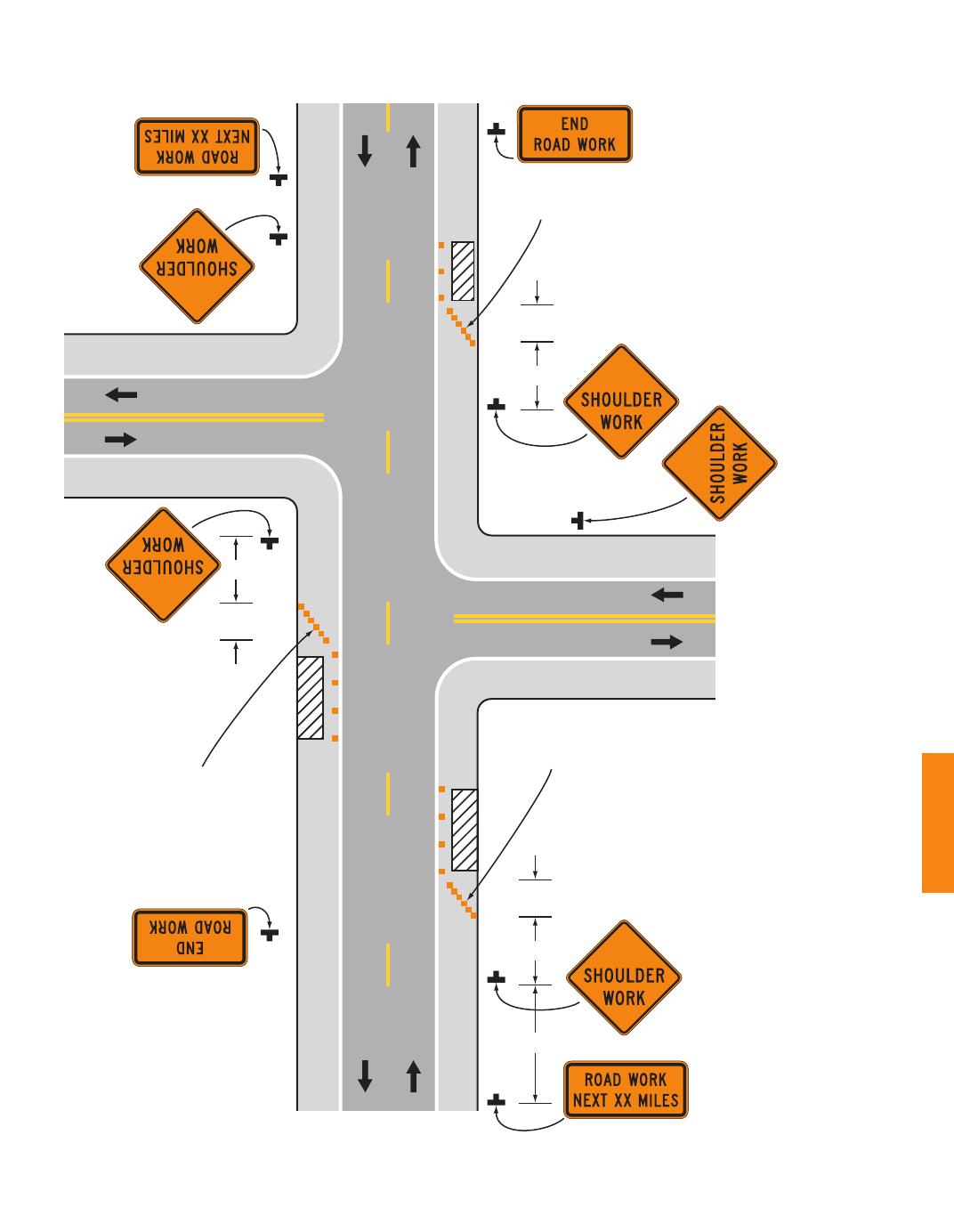
2009 Edition Page 639
Shoulder taper
(see Note 7)
Note: See Tables 6H-2 and 6H-3
for the meaning of the
symbols and/or letter
codes used in this figure.
Typical Application 3
1/3 L
A
Shoulder taper
(see Note 7)
1/3 L
A
B
Shoulder taper
(see Note 7)
1/3 L
A
Figure 6H-3. Work on the Shoulders (TA-3)
December 2009 Sect. 6H.01

Page 640 2009 Edition
Notes for Figure 6H-4—Typical Application 4
Short Duration or Mobile Operation on a Shoulder
Guidance:
1. In those situations where multiple work locations within a limited distance make it practical to place
stationary signs, the distance between the advance warning sign and the work should not exceed 5 miles.
2. In those situations where the distance between the advance signs and the work is 2 miles to 5 miles,
a Supplemental Distance plaque should be used with the ROAD WORK AHEAD sign.
Option:
3. The ROAD WORK NEXT XX MILES sign may be used instead of the ROAD WORK AHEAD sign if
the work locations occur over a distance of more than 2 miles.
4. Stationary warning signs may be omitted for short duration or mobile operations if the work vehicle
displays high-intensity rotating, ashing, oscillating, or strobe lights.
5. Vehicle hazard warning signals may be used to supplement high-intensity rotating, ashing, oscillating,
or strobe lights.
Standard:
6. Vehicle hazard warning signals shall not be used instead of the vehicle’s high-intensity rotating,
ashing, oscillating, or strobe lights.
7. If an arrow board is used for an operation on the shoulder, the caution mode shall be used.
8. Vehicle-mounted signs shall be mounted in a manner such that they are not obscured by equipment
or supplies. Sign legends on vehicle-mounted signs shall be covered or turned from view when work
is not in progress.
Sect. 6H.01 December 2009

2009 Edition Page 641
Note: See Tables 6H-2 and
6H-3 for the meaning
of the symbols and/or
letter codes used in
this figure.
Typical Application 39
(optional)
(optional)
See Note 1
Typical Application 4
Shadow vehicle
Work vehicle
Truck-mounted attenuator
(optional)
Figure 6H-4. Short-Duration or Mobile Operation on a Shoulder (TA-4)
December 2009 Sect. 6H.01

Page 642 2009 Edition
Notes for Figure 6H-5—Typical Application 5
Shoulder Closure on a Freeway
Guidance:
1. SHOULDER CLOSED signs should be used on limited-access highways where there is no opportunity for
disabled vehicles to pull off the roadway.
2. If drivers cannot see a pull-off area beyond the closed shoulder, information regarding the length of the
shoulder closure should be provided in feet or miles, as appropriate.
3. The use of a temporary trafc barrier should be based on engineering judgment.
Standard:
4. Temporary trafc barriers, if used, shall comply with the provisions of Section 6F.85.
Option:
5. The barrier shown in this typical application is an example of one method that may be used to close a
shoulder of a long-term project.
6. The warning lights shown on the barrier may be used.
Sect. 6H.01 December 2009

2009 Edition Page 643
Crash cushion
Note: See Tables 6H-2 and
6H-3 for the meaning
of the symbols and/or
letter codes used in
this figure.
Typical Application 5
500 ft
Barrier and
lights (optional)
1/3 L
A
B
Figure 6H-5. Shoulder Closure on a Freeway (TA-5)
December 2009 Sect. 6H.01

Page 644 2009 Edition
Notes for Figure 6H-6—Typical Application 6
Shoulder Work with Minor Encroachment
Guidance:
1. All lanes should be a minimum of 10 feet in width as measured to the near face of the channelizing
devices.
2. The treatment shown should be used on a minor road having low speeds. For higher-speed trafc
conditions, a lane closure should be used.
Option:
3. For short-term use on low-volume, low-speed roadways with vehicular trafc that does not include longer
and wider heavy commercial vehicles, a minimum lane width of 9 feet may be used.
4. Where the opposite shoulder is suitable for carrying vehicular trafc and of adequate width, lanes may be
shifted by use of closely-spaced channelizing devices, provided that the minimum lane width of 10 feet is
maintained.
5. Additional advance warning may be appropriate, such as a ROAD NARROWS sign.
6. Temporary trafc barriers may be used along the work space.
7. The shadow vehicle may be omitted if a taper and channelizing devices are used.
8. A truck-mounted attenuator may be used on the shadow vehicle.
9. For short-duration work, the taper and channelizing devices may be omitted if a shadow vehicle with
activated high-intensity rotating, ashing, oscillating, or strobe lights is used.
10. Vehicle hazard warning signals may be used to supplement high-intensity rotating, ashing, oscillating, or
strobe lights.
Standard:
11. Vehicle-mounted signs shall be mounted in a manner such that they are not obscured by equipment
or supplies. Sign legends on vehicle-mounted signs shall be covered or turned from view when work
is not in progress.
12. Shadow and work vehicles shall display high-intensity rotating, ashing, oscillating, or strobe lights.
13. Vehicle hazard warning signals shall not be used instead of the vehicle’s high-intensity rotating,
ashing, oscillating, or strobe lights.
Sect. 6H.01 December 2009

2009 Edition Page 645
Buffer space
(optional)
Note: See Tables 6H-2 and
6H-3 for the meaning
of the symbols and/or
letter codes used in
this figure.
Typical Application 6
Truck-mounted
attenuator
(optional)
A
A
1/3 L
Work vehicle
Figure 6H-6. Shoulder Work with Minor Encroachment (TA-6)
10 ft
MIN.
December 2009 Sect. 6H.01

Page 646 2009 Edition
Notes for Figure 6H-7—Typical Application 7
Road Closure with a Diversion
Support:
1. Signs and object markers are shown for one direction of travel only.
Standard:
2. Devices similar to those depicted shall be placed for the opposite direction of travel.
3. Pavement markings no longer applicable to the trafc pattern of the roadway shall be removed or
obliterated before any new trafc patterns are open to trafc.
4. Temporary barriers and end treatments shall be crashworthy.
Guidance:
5. If the tangent distance along the temporary diversion is more than 600 feet, a Reverse Curve sign, left
rst, should be used instead of the Double Reverse Curve sign, and a second Reverse Curve sign, right
rst, should be placed in advance of the second reverse curve back to the original alignment.
6. When the tangent section of the diversion is more than 600 feet, and the diversion has sharp curves with
recommended speeds of 30 mph or less, Reverse Turn signs should be used.
7. Where the temporary pavement and old pavement are different colors, the temporary pavement should
start on the tangent of the existing pavement and end on the tangent of the existing pavement.
Option:
8. Flashing warning lights and/or ags may be used to call attention to the warning signs.
9. On sharp curves, large arrow signs may be used in addition to other advance warning signs.
10. Delineators or channelizing devices may be used along the diversion.
Sect. 6H.01 December 2009

2009 Edition Page 647
Note: See Tables 6H-2 and
6H-3 for the meaning
of the symbols and/or
letter codes used in
this figure.
500 ft
Typical Application 7
Temporary white
edge line
A
B
C
(optional)
Temporary pavement
ends here
(optional)
Crash cushion
(optional)
Crash cushion
(optional)
Temporary pavement
starts here
Temporary double
yellow center line
Figure 6H-7. Road Closure with a Diversion (TA-7)
December 2009 Sect. 6H.01

Page 648 2009 Edition
Notes for Figure 6H-8—Typical Application 8
Road Closure with an Off-Site Detour
Guidance:
1. Regulatory trafc control devices should be modied as needed for the duration of the detour.
Option:
2. If the road is opened for some distance beyond the intersection and/or there are signicant origin/
destination points beyond the intersection, the ROAD CLOSED and DETOUR signs on Type 3 Barricades
may be located at the edge of the traveled way.
3. A Route Sign Directional assembly may be placed on the far left corner of the intersection to augment or
replace the one shown on the near right corner.
4. Flashing warning lights and/or ags may be used to call attention to the advance warning signs.
5. Cardinal direction plaques may be used with route signs.
Sect. 6H.01 December 2009

2009 Edition Page 649
Note: See Tables 6H-2 and
6H-3 for the meaning
of the symbols and/or
letter codes used in
this figure.
Typical Application 8
500 ft
1,000 ft
500 ft
500 ft
200 ft
Figure 6H-8. Road Closure with an Off-Site Detour (TA-8)
December 2009 Sect. 6H.01

Page 650 2009 Edition
Notes for Figure 6H-9—Typical Application 9
Overlapping Routes with a Detour
Support:
1. TTC devices are shown for one direction of travel only.
Standard:
2. Devices similar to those depicted shall be placed for the opposite direction of travel.
Guidance:
3. STOP or YIELD signs displayed to side roads should be installed as needed along the temporary route.
Option:
4. Flashing warning lights and/or ags may be used to call attention to the advance warning signs.
5. Flashing warning lights may be used on the Type 3 Barricades.
6. Cardinal direction plaques may be used with route signs.
Sect. 6H.01 December 2009

2009 Edition Page 651
Note: See Tables 6H-2 and 6H-3 for the
meaning of the symbols and/or
letter codes used in this figure.
Typical Application 9
State Route 4
State Routes
4 and 17
State Route 17
Type 3 Barricade
Note:
All route sign
assemblies illustrated
on this figure that do
not include a DETOUR
auxiliary sign above it
are existing permanent
route sign assemblies.
Figure 6H-9. Overlapping Routes with a Detour (TA-9)
December 2009 Sect. 6H.01

Page 652 2009 Edition
Notes for Figure 6H-10—Typical Application 10
Lane Closure on a Two-Lane Road Using Flaggers
Option:
1. For low-volume situations with short work zones on straight roadways where the agger is visible to road
users approaching from both directions, a single agger, positioned to be visible to road users approaching
from both directions, may be used (see Chapter 6E).
2. The ROAD WORK AHEAD and the END ROAD WORK signs may be omitted for short-duration
operations.
3. Flashing warning lights and/or ags may be used to call attention to the advance warning signs.
A BE PREPARED TO STOP sign may be added to the sign series.
Guidance:
4. The buffer space should be extended so that the two-way trafc taper is placed before a horizontal
(or crest vertical) curve to provide adequate sight distance for the agger and a queue of stopped
vehicles.
Standard:
5. At night, agger stations shall be illuminated, except in emergencies.
Guidance:
6. When used, the BE PREPARED TO STOP sign should be located between the Flagger sign and the
ONE LANE ROAD sign.
7. When a grade crossing exists within or upstream of the transition area and it is anticipated that queues
resulting from the lane closure might extend through the grade crossing, the TTC zone should be extended
so that the transition area precedes the grade crossing.
8. When a grade crossing equipped with active warning devices exists within the activity area, provisions
should be made for keeping aggers informed as to the activation status of these warning devices.
9. When a grade crossing exists within the activity area, drivers operating on the left-hand side of the
normal center line should be provided with comparable warning devices as for drivers operating on the
right-hand side of the normal center line.
10. Early coordination with the railroad company or light rail transit agency should occur before work
starts.
Option:
11. A agger or a uniformed law enforcement ofcer may be used at the grade crossing to minimize the
probability that vehicles are stopped within 15 feet of the grade crossing, measured from both sides of the
outside rails.
Sect. 6H.01 December 2009

2009 Edition Page 653
Note: See Tables 6H-2 and 6H-3
for the meaning of the
symbols and/or letter
codes used in this figure.
50 to 100 ft
(optional)
A
B
C
(optional)
50 to 100 ft
A
B
C
Typical Application 10
Figure 6H-10. Lane Closure on a Two-Lane Road Using Flaggers (TA-10)
December 2009 Sect. 6H.01

Page 654 2009 Edition
Notes for Figure 6H-11—Typical Application 11
Lane Closure on a Two-Lane Road with Low Trafc Volumes
Option:
1. This TTC zone application may be used as an alternate to the TTC application shown in Figure 6H-10
(using aggers) when the following conditions exist:
a. Vehicular trafc volume is such that sufcient gaps exist for vehicular trafc that must yield.
b. Road users from both directions are able to see approaching vehicular trafc through and beyond the
worksite and have sufcient visibility of approaching vehicles.
2. The Type B ashing warning lights may be placed on the ROAD WORK AHEAD and the
ONE LANE ROAD AHEAD signs whenever a night lane closure is necessary.
Sect. 6H.01 December 2009

2009 Edition Page 655
(optional)
(see Section 3B.16)
Note: See Tables 6H-2 and 6H-3
for the meaning of the
symbols and/or letter
codes used in this figure.
A
B
C
(optional)
Typical Application 11
(optional)
(optional)
15 ft
Buffer space (optional)
(optional)
(optional)
(optional)
(optional)
B
C
(optional)
50 to 100 ft
50 to 100 ft
Buffer space (optional)
Figure 6H-11. Lane Closure on a Two-Lane Road
with Low Traffic Volumes (TA-11)
December 2009 Sect. 6H.01

Page 656 2009 Edition
Notes for Figure 6H-12—Typical Application 12
Lane Closure on a Two-Lane Road Using Trafc Control Signals
Standard:
1. Temporary trafc control signals shall be installed and operated in accordance with the provisions
of Part 4. Temporary trafc control signals shall meet the physical display and operational
requirements of conventional trafc control signals.
2. Temporary trafc control signal timing shall be established by authorized ofcials. Durations of
red clearance intervals shall be adequate to clear the one-lane section of conicting vehicles.
3. When the temporary trafc control signal is changed to the ashing mode, either manually or
automatically, red signal indications shall be ashed to both approaches.
4. Stop lines shall be installed with temporary trafc control signals for intermediate and long-term
closures. Existing conicting pavement markings and raised pavement marker reectors between
the activity area and the stop line shall be removed. After the temporary trafc control signal
is removed, the stop lines and other temporary pavement markings shall be removed and the
permanent pavement markings restored.
5. Safeguards shall be incorporated to avoid the possibility of conicting signal indications at each end
of the TTC zone.
Guidance:
6. Where no-passing lines are not already in place, they should be added.
7. Adjustments in the location of the advance warning signs should be made as needed to accommodate the
horizontal or vertical alignment of the roadway, recognizing that the distances shown for sign spacings
are minimums. Adjustments in the height of the signal heads should be made as needed to conform to the
vertical alignment.
Option:
8. Flashing warning lights shown on the ROAD WORK AHEAD and the ONE LANE ROAD AHEAD
signs may be used.
9. Removable pavement markings may be used.
Support:
10. Temporary trafc control signals are preferable to aggers for long-term projects and other activities that
would require agging at night.
11. The maximum length of activity area for one-way operation under temporary trafc control signal control
is determined by the capacity required to handle the peak demand.
Sect. 6H.01 December 2009

2009 Edition Page 657
Note: See Tables 6H-2 and 6H-3
for the meaning of the
symbols and/or letter
codes used in this figure.
A
(optional)
(optional)
(optional)
B
C
A
B
C
Lighting
(optional)
Temporary
markings
500 to
600 ft
(optional)
(optional)
(optional)
Temporary
markings
Typical Application 12
500 to
600 ft
50 to 100 ft
50 to 100 ft
40 to 180 ft
Lighting
(optional)
40 to 180 ft
Figure 6H-12. Lane Closure on a Two-Lane Road Using
Traffic Control Signals (TA-12)
December 2009 Sect. 6H.01

Page 658 2009 Edition
Notes for Figure 6H-13—Typical Application 13
Temporary Road Closure
Support:
1. Conditions represented are a planned closure not exceeding 20 minutes during the daytime.
Standard:
2. A agger or uniformed law enforcement ofcer shall be used for this application. The agger, if
used for this application, shall follow the procedures provided in Sections 6E.07 and 6E.08.
Guidance:
3. The uniformed law enforcement ofcer, if used for this application, should follow the procedures
provided in Sections 6E.07 and 6E.08.
Option:
4. A BE PREPARED TO STOP sign may be added to the sign series.
Guidance:
5. When used, the BE PREPARED TO STOP sign should be located before the Flagger symbol sign.
Sect. 6H.01 December 2009

2009 Edition Page 659
Note: See Tables 6H-2 and 6H-3
for the meaning of the
symbols and/or letter
codes used in this figure.
A
B
C
A
B
C
Typical Application 13
(optional)
Buffer
space
(optional)
(optional)
Buffer
space
(optional)
Figure 6H-13. Temporary Road Closure (TA-13)
December 2009 Sect. 6H.01

Page 660 2009 Edition
Notes for Figure 6H-14—Typical Application 14
Haul Road Crossing
Guidance:
1. Floodlights should be used to illuminate haul road crossings where existing light is inadequate.
2. Where no-passing lines are not already in place, they should be added.
Standard:
3. The trafc control method selected shall be used in both directions.
Flagging Method
4. When a road used exclusively as a haul road is not in use, the haul road shall be closed with Type 3
Barricades and the Flagger symbol signs covered.
5. The agger shall follow the procedures provided in Sections 6E.07 and 6E.08.
6. At night, agger stations shall be illuminated, except in emergencies.
Signalized Method
7. When a road used exclusively as a haul road is not in use, the haul road shall be closed with Type
3 Barricades. The signals shall either ash yellow on the main road or be covered, and the Signal
Ahead and STOP HERE ON RED signs shall be covered or hidden from view.
8. The temporary trafc control signals shall control both the highway and the haul road and shall
meet the physical display and operational requirements of conventional trafc control signals as
described in Part 4. Trafc control signal timing shall be established by authorized ofcials.
9. Stop lines shall be used on existing highway with temporary trafc control signals.
10. Existing conicting pavements markings between the stop lines shall be removed. After the
temporary trafc control signal is removed, the stop lines and other temporary pavement markings
shall be removed and the permanent pavement markings restored.
Sect. 6H.01 December 2009

2009 Edition Page 661
A - USING TEMPORARY TRAFFIC CONTROL SIGNALS
See Note 7 See Note 7
A
B
Typical Application 14
Temporary
marking
(optional)
Haul Road
Temporary
marking
(optional)
Haul Road
(optional)
(optional)
See Note 4 See Note 4
Note: See Tables 6H-2 and 6H-3
for the meaning of the
symbols and/or letter
codes used in this figure.
40 to
180 ft
(optional)
30 ft
A
B
C
B - USING FLAGGERS
Figure 6H-14. Haul Road Crossing (TA-14)
December 2009 Sect. 6H.01

Page 662 2009 Edition
Notes for Figure 6H-15—Typical Application 15
Work in the Center of a Road with Low Trafc Volumes
Guidance:
1. The lanes on either side of the center work space should have a minimum width of 10 feet as measured
from the near edge of the channelizing devices to the edge of the pavement or the outside edge of the
paved shoulder.
Option:
2. Flashing warning lights and/or ags may be used to call attention to the advance warning signs.
3. If the closure continues overnight, warning lights may be used on the channelizing devices.
4. A lane width of 9 feet may be used for short-term stationary work on low-volume, low-speed roadways
when motor vehicle trafc does not include longer and wider heavy commercial vehicles.
5. A work vehicle displaying high-intensity rotating, ashing, oscillating, or strobe lights may be used instead
of the channelizing devices forming the tapers or the high-level warning devices.
6. Vehicle hazard warning signals may be used to supplement high-intensity rotating, ashing, oscillating, or
strobe lights.
Standard:
7. Vehicle hazard warning signals shall not be used instead of the vehicle’s high-intensity rotating,
ashing, oscillating, or strobe lights.
Sect. 6H.01 December 2009

2009 Edition Page 663
(optional)
(optional)
Typical Application 15
10 feet MIN. to edge
of pavement or outside
edge of paved shoulder
1/2 L
Note: See Tables 6H-2 and 6H-3
for the meaning of the
symbols and/or letter
codes used in this figure.
A
1/2 L
A
Figure 6H-15. Work in the Center of a Road with Low Traffic Volumes (TA-15)
December 2009 Sect. 6H.01

Page 664 2009 Edition
Notes for Figure 6H-16—Typical Application 16
Surveying Along the Center Line of a Road with Low Trafc Volumes
Guidance:
1. The lanes on either side of the center work space should have a minimum width of 10 feet as measured
from the near edge of the channelizing devices to the edge of the pavement or the outside edge of the
paved shoulder.
2. Cones should be placed 6 to 12 inches on either side of the center line.
3. A agger should be used to warn workers who cannot watch road users.
Standard:
4. For surveying on the center line of a high-volume road, one lane shall be closed using the
information illustrated in Figure 6H-10.
Option:
5. A high-level warning device may be used to protect a surveying device, such as a target on a tripod.
6. Cones may be omitted for a cross-section survey.
7. ROAD WORK AHEAD signs may be used in place of the SURVEY CREW AHEAD signs.
8. Flags may be used to call attention to the advance warning signs.
9. If the work is along the shoulder, the agger may be omitted.
10. For a survey along the edge of the road or along the shoulder, cones may be placed along the edge line.
11. A BE PREPARED TO STOP sign may be added to the sign series.
Guidance:
12. When used, the BE PREPARED TO STOP sign should be located before the Flagger symbol sign.
Sect. 6H.01 December 2009

2009 Edition Page 665
Buffer space
Buffer space
Typical Application 16
Note: See Tables 6H-2 and 6H-3
for the meaning of the
symbols and/or letter
codes used in this figure.
A
B
A
B
10 feet MIN. to edge
of pavement or outside
edge of paved shoulder
Figure 6H-16. Surveying Along the Center Line of a Road
with Low Traffic Volumes (TA-16)
December 2009 Sect. 6H.01

Page 666 2009 Edition
Notes for Figure 6H-17—Typical Application 17
Mobile Operations on a Two-Lane Road
Standard:
1. Vehicle-mounted signs shall be mounted in a manner such that they are not obscured by equipment
or supplies. Sign legends on vehicle-mounted signs shall be covered or turned from view when work
is not in progress.
2. Shadow and work vehicles shall display high-intensity rotating, ashing, oscillating, or strobe lights.
3. If an arrow board is used, it shall be used in the caution mode.
Guidance:
4. Where practical and when needed, the work and shadow vehicles should pull over periodically to allow
vehicular trafc to pass.
5. Whenever adequate stopping sight distance exists to the rear, the shadow vehicle should maintain the
minimum distance from the work vehicle and proceed at the same speed. The shadow vehicle should
slow down in advance of vertical or horizontal curves that restrict sight distance.
6. The shadow vehicles should also be equipped with two high-intensity ashing lights mounted on the rear,
adjacent to the sign.
Option:
7. The distance between the work and shadow vehicles may vary according to terrain, paint drying time, and
other factors.
8. Additional shadow vehicles to warn and reduce the speed of oncoming or opposing vehicular trafc may
be used. Law enforcement vehicles may be used for this purpose.
9. A truck-mounted attenuator may be used on the shadow vehicle or on the work vehicle.
10. If the work and shadow vehicles cannot pull over to allow vehicular trafc to pass frequently, a DO NOT
PASS sign may be placed on the rear of the vehicle blocking the lane.
Support:
11. Shadow vehicles are used to warn motor vehicle trafc of the operation ahead.
Standard:
12. Vehicle hazard warning signals shall not be used instead of the vehicle’s high-intensity rotating,
ashing, oscillating, or strobe lights.
Sect. 6H.01 December 2009
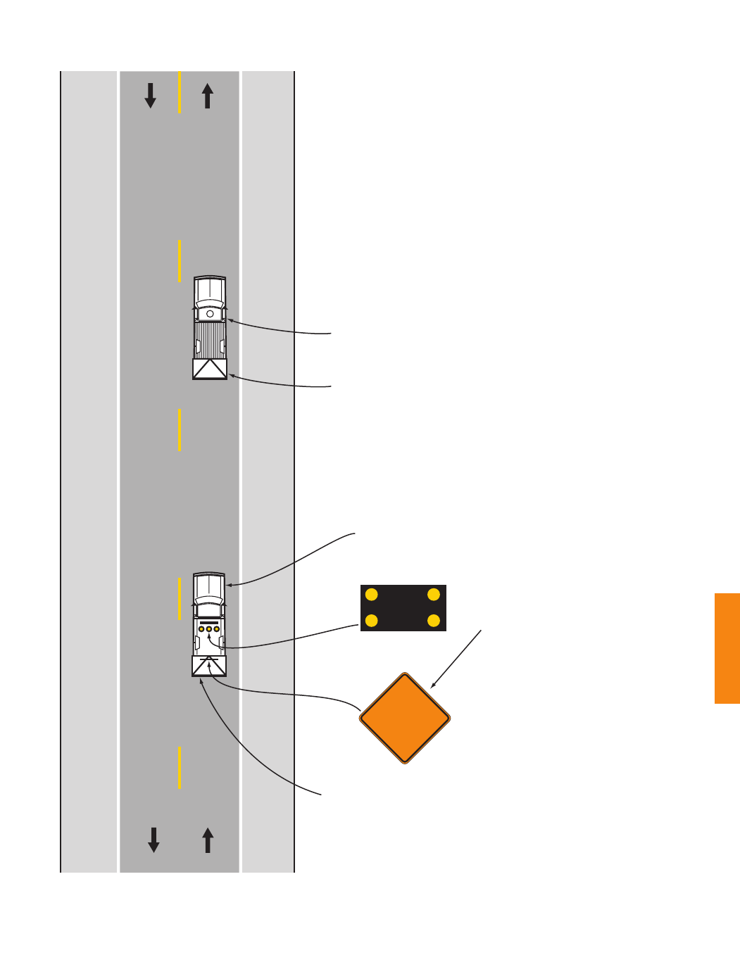
2009 Edition Page 667
Truck-mounted attenuator
(optional)
Work vehicle
Shadow vehicle
Use sign shape
and legend
appropriate
to the type
of work
Truck-mounted attenuator
(optional)
Typical Application 17
Note: See Tables 6H-2 and 6H-3
for the meaning of the
symbols and/or letter
codes used in this figure.
(optional)
Figure 6H-17. Mobile Operations on a Two-Lane Road (TA-17)
December 2009 Sect. 6H.01

Page 668 2009 Edition
Notes for Figure 6H-18—Typical Application 18
Lane Closure on a Minor Street
Standard:
1. This TTC shall be used only for low-speed facilities having low trafc volumes.
Option:
2. Where the work space is short, where road users can see the roadway beyond, and where volume is low,
vehicular trafc may be self-regulating.
Standard:
3. Where vehicular trafc cannot effectively self-regulate, one or two aggers shall be used as
illustrated in Figure 6H-10.
Option:
4. Flashing warning lights and/or ags may be used to call attention to the advance warning signs.
5. A truck-mounted attenuator may be used on the work vehicle and the shadow vehicle.
Sect. 6H.01 December 2009

2009 Edition Page 669
Typical Application 18
Note: See Tables 6H-2 and 6H-3
for the meaning of the
symbols and/or letter
codes used in this figure.
Work vehicle (optional)
Truck-mounted attenuator (optional)
Buffer space
(optional)
50 to 100 ft
A
A
Figure 6H-18. Lane Closure on a Minor Street (TA-18)
December 2009 Sect. 6H.01

Page 670 2009 Edition
Notes for Figure 6H-19—Typical Application 19
Detour for One Travel Direction
Guidance:
1. This plan should be used for streets without posted route numbers.
2. On multi-lane streets, Detour signs with an Advance Turn Arrow should be used in advance of a turn.
Option:
3. The STREET CLOSED legend may be used in place of ROAD CLOSED.
4. Additional DO NOT ENTER signs may be used at intersections with intervening streets.
5. Warning lights may be used on Type 3 Barricades.
6. Detour signs may be located on the far side of intersections.
7. A Street Name sign may be mounted with the Detour sign. The Street Name sign may be either white on
green or black on orange.
Standard:
8. When used, the Street Name sign shall be placed above the Detour sign.
Sect. 6H.01 December 2009

2009 Edition Page 671
Typical Application 19
Note: See Tables 6H-2 and 6H-3
for the meaning of the
symbols and/or letter
codes used in this figure.
A
B
100 ft
Figure 6H-19. Detour for One Travel Direction (TA-19)
December 2009 Sect. 6H.01

Page 672 2009 Edition
Notes for Figure 6H-20—Typical Application 20
Detour for a Closed Street
Guidance:
1. This plan should be used for streets without posted route numbers.
2. On multi-lane streets, Detour signs with an Advance Turn Arrow should be used in advance of a turn.
Option:
3. Flashing warning lights and/or ags may be used to call attention to the advance warning signs.
4. Flashing warning lights may be used on Type 3 Barricades.
5. Detour signs may be located on the far side of intersections. A Detour sign with an advance arrow may be
used in advance of a turn.
6. A Street Name sign may be mounted with the Detour sign. The Street Name sign may be either white on
green or black on orange.
Standard:
7. When used, the Street Name sign shall be placed above the Detour sign.
Support:
8. See Figure 6H-9 for the information for detouring a numbered highway.
Sect. 6H.01 December 2009

2009 Edition Page 673
Typical Application 20
Note: See Tables 6H-2 and 6H-3
for the meaning of the
symbols and/or letter
codes used in this figure.
A
B
A
B
Figure 6H-20. Detour for a Closed Street (TA-20)
December 2009 Sect. 6H.01

Page 674 2009 Edition
Notes for Figure 6H-21—Typical Application 21
Lane Closure on the Near Side of an Intersection
Standard:
1. The merging taper shall direct vehicular trafc into either the right-hand or left-hand lane, but not
both.
Guidance:
2. In this typical application, a left taper should be used so that right-turn movements will not impede
through motor vehicle trafc. However, the reverse should be true for left-turn movements.
3. If the work space extends across a crosswalk, the crosswalk should be closed using the information and
devices shown in Figure 6H-29.
Option:
4. Flashing warning lights and/or ags may be used to call attention to the advance warning signs.
5. A shadow vehicle with a truck-mounted attenuator may be used.
6. A work vehicle with high-intensity rotating, ashing, oscillating, or strobe lights may be used with the
high-level warning device.
7. Vehicle hazard warning signals may be used to supplement high-intensity rotating, ashing, oscillating, or
strobe lights.
Standard:
8. Vehicle hazard warning signals shall not be used instead of the vehicle’s high-intensity rotating,
ashing, oscillating, or strobe lights.
Sect. 6H.01 December 2009

2009 Edition Page 675
Typical Application 21
Note: See Tables 6H-2 and 6H-3
for the meaning of the
symbols and/or letter
codes used in this figure.
Work vehicle
(optional)
(optional)
Buffer space
(optional)
L
A
B
Figure 6H-21. Lane Closure on the Near Side of an Intersection (TA-21)
December 2009 Sect. 6H.01

Page 676 2009 Edition
Notes for Figure 6H-22—Typical Application 22
Right-Hand Lane Closure on the Far Side of an Intersection
Guidance:
1. If the work space extends across a crosswalk, the crosswalk should be closed using the information and
devices shown in Figure 6H-29.
Option:
2. The normal procedure is to close on the near side of the intersection any lane that is not carried through
the intersection. However, when this results in the closure of a right-hand lane having signicant right
turning movements, then the right-hand lane may be restricted to right turns only, as shown. This
procedure increases the through capacity by eliminating right turns from the open through lane.
3. For intersection approaches reduced to a single lane, left-turning movements may be prohibited to
maintain capacity for through vehicular trafc.
4. Flashing warning lights and/or ags may be used to call attention to the advance warning signs.
5. Where the turning radius is large, it may be possible to create a right-turn island using channelizing
devices or pavement markings.
Sect. 6H.01 December 2009

2009 Edition Page 677
Typical Application 22
Note: See Tables 6H-2 and 6H-3
for the meaning of the
symbols and/or letter
codes used in this figure.
(optional)
(optional)
(optional)
(optional)
(optional)
A
A
B
A
A
Figure 6H-22. Right-Hand Lane Closure on the Far Side of an Intersection (TA-22)
December 2009 Sect. 6H.01

Page 678 2009 Edition
Notes for Figure 6H-23—Typical Application 23
Left-Hand Lane Closure on the Far Side of an Intersection
Guidance:
1. If the work space extends across a crosswalk, the crosswalk should be closed using the information and
devices shown in Figure 6H-29.
Option:
2. Flashing warning lights and/or ags may be used to call attention to the advance warning signs.
3. The normal procedure is to close on the near side of the intersection any lane that is not carried through
the intersection. However, when this results in the closure of a left lane having signicant left-turning
movements, then the left lane may be reopened as a turn bay for left turns only, as shown.
Support:
4. By rst closing off the left lane and then reopening it as a turn bay, the left-turn bay allows storage of
turning vehicles so that the movement of through trafc is not impeded. A left-turn bay that is long
enough to accommodate all turning vehicles during a trafc signal cycle will provide the maximum
benet for through trafc. Also, an island is created with channelizing devices that allows the LEFT
LANE MUST TURN LEFT sign to be repeated on the left adjacent to the lane that it controls.
Sect. 6H.01 December 2009

2009 Edition Page 679
Typical Application 23
Note: See Tables 6H-2 and 6H-3
for the meaning of the
symbols and/or letter
codes used in this figure.
A
A
A
A
(optional)
100 ft
B
C
L
December 2009 Sect. 6H.01

Page 680 2009 Edition
Notes for Figure 6H-24—Typical Application 24
Half Road Closure on the Far Side of an Intersection
Guidance:
1. If the work space extends across a crosswalk, the crosswalk should be closed using the information and
devices shown in Figure 6H-29.
2. When turn prohibitions are implemented, two turn prohibition signs should be used, one on the near side
and, space permitting, one on the far side of the intersection.
Option:
3. A buffer space may be used between opposing directions of vehicular trafc as shown in this application.
4. The normal procedure is to close on the near side of the intersection any lane that is not carried through
the intersection. However, if there is a signicant right-turning movement, then the right-hand lane may
be restricted to right turns only, as shown.
5. Where the turning radius is large, a right-turn island using channelizing devices or pavement markings
may be used.
6. There may be insufcient space to place the back-to-back Keep Right sign and No Left Turn symbol signs
at the end of the row of channelizing devices separating opposing vehicular trafc ows. In this situation,
the No Left Turn symbol sign may be placed on the right and the Keep Right sign may be omitted.
7. For intersection approaches reduced to a single lane, left-turning movements may be prohibited to
maintain capacity for through vehicular trafc.
8. Flashing warning lights and/or ags may be used to call attention to advance warning signs.
9. Temporary pavement markings may be used to delineate the travel path through the intersection.
Support:
10. Keeping the right-hand lane open increases the through capacity by eliminating right turns from the open
through lane.
11. A temporary turn island reinforces the nature of the temporary exclusive right-turn lane and enables a
second RIGHT LANE MUST TURN RIGHT sign to be placed in the island.
Sect. 6H.01 December 2009

2009 Edition Page 681
Typical Application 24
Note: See Tables 6H-2 and 6H-3
for the meaning of the
symbols and/or letter
codes used in this figure.
(optional)
(optional)
(optional)
(optional)
A
L
A
B
C
1/2 L
Buffer
space
(optional)
Optional
temporary
markings
A
A
B
C
Figure 6H-24. Half Road Closure on the Far Side of an Intersection (TA-24)
December 2009 Sect. 6H.01

Page 682 2009 Edition
Notes for Figure 6H-25—Typical Application 25
Multiple Lane Closures at an Intersection
Guidance:
1. If the work space extends across a crosswalk, the crosswalk should be closed using the information and
devices shown in Figure 6H-29.
2. If the left through lane is closed on the near-side approach, the LEFT LANE MUST TURN LEFT sign
should be placed in the median to discourage through vehicular trafc from entering the left-turn bay.
Support:
3. The normal procedure is to close on the near side of the intersection any lane that is not carried through
the intersection.
Option:
4. If the left-turning movement that normally uses the closed turn bay is small and/or the gaps in opposing
vehicular trafc are frequent, left turns may be permitted on that approach.
5. Flashing warning lights and/or ags may be used to call attention to the advance warning signs.
Sect. 6H.01 December 2009

2009 Edition Page 683
Note: See Tables 6H-2 and 6H-3
for the meaning of the
symbols and/or letter
codes used in this figure.
(optional)
A
A
A
Typical Application 25
A
B
C
1/2 L
(optional)
Figure 6H-25. Multiple Lane Closures at an Intersection (TA-25)
December 2009 Sect. 6H.01

Page 684 2009 Edition
Notes for Figure 6H-26—Typical Application 26
Closure in the Center of an Intersection
Guidance:
1. All lanes should be a minimum of 10 feet in width as measured to the near face of the channelizing
devices.
Option:
2. A high-level warning device may be placed in the work space, if there is sufcient room.
3. For short-term use on low-volume, low-speed roadways with vehicular trafc that does not include longer
and wider heavy commercial vehicles, a minimum lane width of 9 feet may be used.
4. Flashing warning lights and/or ags may be used to call attention to advance warning signs.
5. Unless the streets are wide, it may be physically impossible to turn left, especially for large vehicles. Left
turns may be prohibited as required by geometric conditions.
6. For short-duration work operations, the channelizing devices may be eliminated if a vehicle displaying
high-intensity rotating, ashing, oscillating, or strobe lights is positioned in the work space.
7. Vehicle hazard warning signals may be used to supplement high-intensity rotating, ashing, oscillating, or
strobe lights.
Standard:
8. Vehicle hazard warning signals shall not be used instead of the vehicle’s high-intensity rotating,
ashing, oscillating, or strobe lights.
Sect. 6H.01 December 2009

2009 Edition Page 685
(optional)
Note: See Tables 6H-2 and 6H-3
for the meaning of the
symbols and/or letter codes
used in this figure.
Typical Application 26
1/2 L
A
10 ft
MIN.
1/2 L
A
10 ft MIN.
1/2 L
A
1/2 L
A
10 ft MIN.
10 ft
MIN.
Figure 6H-26. Closure in the Center of an Intersection (TA-26)
December 2009 Sect. 6H.01

Page 686 2009 Edition
Notes for Figure 6H-27—Typical Application 27
Closure at the Side of an Intersection
Guidance:
1. The situation depicted can be simplied by closing one or more of the intersection approaches. If this
cannot be done, and/or when capacity is a problem, through vehicular trafc should be directed to other
roads or streets.
2. Depending on road user conditions, agger(s) or uniformed law enforcement ofcer(s) should be used to
direct road users within the intersection.
Standard:
3. At night, agger stations shall be illuminated, except in emergencies.
Option:
4. Flashing warning lights and/or ags may be used to call attention to the advance warning signs.
5. For short-duration work operations, the channelizing devices may be eliminated if a vehicle displaying
high-intensity rotating, ashing, oscillating, or strobe lights is positioned in the work space.
6. A BE PREPARED TO STOP sign may be added to the sign series.
Guidance:
7. When used, the BE PREPARED TO STOP sign should be located before the Flagger symbol sign.
8. ONE LANE ROAD AHEAD signs should also be used to provide adequate advance warning.
Support:
9. Turns can be prohibited as required by vehicular trafc conditions. Unless the streets are wide, it might be
physically impossible to make certain turns, especially for large vehicles.
Option:
10. Vehicle hazard warning signals may be used to supplement high-intensity rotating, ashing, oscillating, or
strobe lights.
Standard:
11. Vehicle hazard warning signals shall not be used instead of the vehicle’s high-intensity rotating,
ashing, oscillating, or strobe lights.
Sect. 6H.01 December 2009

2009 Edition Page 687
See Note 2 for flagger information
Note: See Tables 6H-2 and 6H-3 for the
meaning of the symbols and/or letter
codes used in this figure.
Typical Application 27
A
50 to 100 ft
BC
50 to
100 ft
50 to
100 ft
A
B
C
A
B
C
(optional)
A B
C
(optional)
Figure 6H-27. Closure at the Side of an Intersection (TA-27)
December 2009 Sect. 6H.01

Page 688 2009 Edition
Notes for Figure 6H-28—Typical Application 28
Sidewalk Detour or Diversion
Standard:
1. When crosswalks or other pedestrian facilities are closed or relocated, temporary facilities shall be
detectable and shall include accessibility features consistent with the features present in the existing
pedestrian facility.
Guidance:
2. Where high speeds are anticipated, a temporary trafc barrier and, if necessary, a crash cushion should
be used to separate the temporary sidewalks from vehicular trafc.
3. Audible information devices should be considered where midblock closings and changed crosswalk areas
cause inadequate communication to be provided to pedestrians who have visual disabilities.
Option:
4. Street lighting may be considered.
5. Only the TTC devices related to pedestrians are shown. Other devices, such as lane closure signing or
ROAD NARROWS signs, may be used to control vehicular trafc.
6. For nighttime closures, Type A Flashing warning lights may be used on barricades that support signs and
close sidewalks.
7. Type C Steady-Burn or Type D 360-degree Steady-Burn warning lights may be used on channelizing
devices separating the temporary sidewalks from vehicular trafc ow.
8. Signs, such as KEEP RIGHT (LEFT), may be placed along a temporary sidewalk to guide or direct
pedestrians.
Sect. 6H.01 December 2009

2009 Edition Page 689
36 inches
MIN.
Note: See Tables 6H-2 and 6H-3 for the meaning
of the symbols and/or letter codes used in
this figure.
Typical Application 28
(optional)
SIDEWALK DETOUR
SIDEWALK DIVERSION
Figure 6H-28. Sidewalk Detour or Diversion (TA-28)
December 2009 Sect. 6H.01

Page 690 2009 Edition
Notes for Figure 6H-29—Typical Application 29
Crosswalk Closures and Pedestrian Detours
Standard:
1. When crosswalks or other pedestrian facilities are closed or relocated, temporary facilities shall be
detectable and shall include accessibility features consistent with the features present in the existing
pedestrian facility.
2. Curb parking shall be prohibited for at least 50 feet in advance of the midblock crosswalk.
Guidance:
3. Audible information devices should be considered where midblock closings and changed crosswalk areas
cause inadequate communication to be provided to pedestrians who have visual disabilities.
4. Pedestrian trafc signal displays controlling closed crosswalks should be covered or deactivated.
Option:
5. Street lighting may be considered.
6. Only the TTC devices related to pedestrians are shown. Other devices, such as lane closure signing or
ROAD NARROWS signs, may be used to control vehicular trafc.
7. For nighttime closures, Type A Flashing warning lights may be used on barricades supporting signs and
closing sidewalks.
8. Type C Steady-Burn or Type D 360-degree Steady-Burn warning lights may be used on channelizing
devices separating the work space from vehicular trafc.
9. In order to maintain the systematic use of the uorescent yellow-green background for pedestrian, bicycle,
and school warning signs in a jurisdiction, the uorescent yellow-green background for pedestrian, bicycle,
and school warning signs may be used in TTC zones.
Sect. 6H.01 December 2009

2009 Edition Page 691
Note: For long-term stationary
work, the double yellow
center line and/or
lane lines should be
removed between the
crosswalk lines.
See Tables 6H-2 and 6H-3
for the meaning of the
symbols and/or letter
codes used in this figure.
Typical Application 29
Temporary
marking for
crosswalk lines
(cross-hatching
optional)
(optional)
Figure 6H-29. Crosswalk Closures and Pedestrian Detours (TA-29)
December 2009 Sect. 6H.01

Page 692 2009 Edition
Notes for Figure 6H-30—Typical Application 30
Interior Lane Closure on a Multi-Lane Street
Guidance:
1. This information applies to low-speed, low-volume urban streets. Where speed or volume is higher,
additional signing such as LEFT LANE CLOSED XX FT should be used between the signs shown.
Option:
2. The closure of the adjacent interior lane in the opposing direction may not be necessary, depending upon
the activity being performed and the work space needed for the operation.
3. Shadow vehicles with a truck-mounted attenuator may be used.
Sect. 6H.01 December 2009

2009 Edition Page 693
Note: See Tables 6H-2 and 6H-3
for the meaning of the
symbols and/or letter
codes used in this figure.
Typical Application 30
(optional)
Buffer space
(optional)
Truck-mounted attenuator
(optional)
Work vehicle
(optional)
Buffer space
(optional)
L
A
B
L
A
B
Figure 6H-30. Interior Lane Closure on a Multi-Lane Street (TA-30)
December 2009 Sect. 6H.01

Page 694 2009 Edition
Notes for Figure 6H-31—Typical Application 31
Lane Closure on a Street with Uneven Directional Volumes
Standard:
1. The illustrated information shall be used only when the vehicular trafc volume indicates that two
lanes of vehicular trafc shall be maintained in the direction of travel for which one lane is closed.
Option:
2. The procedure may be used during a peak period of vehicular trafc and then changed to provide two
lanes in the other direction for the other peak.
Guidance:
3. For high speeds, a LEFT LANE CLOSED XX FT sign should be added for vehicular trafc approaching
the lane closure, as shown in Figure 6H-32.
4. Conicting pavement markings should be removed for long-term projects. For short-term and
intermediate-term projects where this is not practical, the channelizing devices in the area where the
pavement markings conict should be placed at a maximum spacing of 1/2 S feet where S is the speed in
mph. Temporary markings should be installed where needed.
5. If the lane shift has curves with recommended speeds of 30 mph or less, Reverse Turn signs should be
used.
6. Where the shifted section is long, a Reverse Curve sign should be used to show the initial shift and a
second sign should be used to show the return to the normal alignment.
7. If the tangent distance along the temporary diversion is less than 600 feet, the Double Reverse Curve sign
should be used at the location of the rst Two Lane Reverse Curve sign. The second Two Lane Reverse
Curve sign should be omitted.
Standard:
8. The number of lanes illustrated on the Reverse Curve or Double Reverse Curve signs shall be the
same as the number of through lanes available to road users, and the direction of the reverse curves
shall be appropriately illustrated.
Option:
9. A longitudinal buffer space may be used in the activity area to separate opposing vehicular trafc.
10. Where two or more lanes are being shifted, a W1-4 (or W1-3) sign with an ALL LANES (W24-1cP)
plaque (see Figure 6F-4) may be used instead of a sign that illustrates the number of lanes.
11. Where more than three lanes are being shifted, the Reverse Curve (or Turn) sign may be rectangular.
12. A work vehicle or a shadow vehicle may be equipped with a truck-mounted attenuator.
Sect. 6H.01 December 2009

2009 Edition Page 695
Note: See Tables 6H-2 and
6H-3 for the meaning
of the symbols and/or
letter codes used in
this figure.
Typical Application 31
(optional)
1/2 L
A
B
L
Buffer space
(optional)
Temporary solid
white lane line
4S ft*
A
100 ft
B
Buffer space
(optional)
1/2 L
A
*S = speed in mph
Figure 6H-31. Lane Closures on a Street with Uneven
Directional Volumes (TA-31)
December 2009 Sect. 6H.01

Page 696 2009 Edition
Notes for Figure 6H-32—Typical Application 32
Half Road Closure on a Multi-Lane, High-Speed Highway
Standard:
1. Pavement markings no longer applicable shall be removed or obliterated as soon as practical.
Except for intermediate-term and short-term situations, temporary markings shall be provided to
clearly delineate the temporary travel path. For short-term and intermediate-term situations where
it is not feasible to remove and restore pavement markings, channelization shall be made dominant
by using a very close device spacing.
Guidance:
2. When paved shoulders having a width of 8 feet or more are closed, channelizing devices should be used
to close the shoulder in advance of the merging taper to direct vehicular trafc to remain within the
traveled way.
3. Where channelizing devices are used instead of pavement markings, the maximum spacing should be 1/2
S feet where S is the speed in mph.
4. If the tangent distance along the temporary diversion is less than 600 feet, a Double Reverse Curve sign
should be used instead of the rst Reverse Curve sign, and the second Reverse Curve sign should be
omitted.
Option:
5. Warning lights may be used to supplement channelizing devices at night.
6. A truck-mounted attenuator may be used on the work vehicle and/or the shadow vehicle.
Sect. 6H.01 December 2009

2009 Edition Page 697
Shoulder taper
(see Note 2)
Note: See Tables 6H-2 and 6H-3
for the meaning of the
symbols and/or letter
codes used in this figure.
Typical Application 32
Buffer space
(optional)
1/2 L MIN.
A
B
L
Temporary
yellow lines
B
C
Temporary white
edge line
(optional)
1/2 L MIN.
A
B
L
B
C
1/2 L MIN.
Figure 6H-32. Half Road Closure on a Multi-Lane,
High-Speed Highway (TA-32)
December 2009 Sect. 6H.01

Page 698 2009 Edition
Notes for Figure 6H-33—Typical Application 33
Stationary Lane Closure on a Divided Highway
Standard:
1. This information also shall be used when work is being performed in the lane adjacent to the
median on a divided highway. In this case, the LEFT LANE CLOSED signs and the corresponding
Lane Ends signs shall be substituted.
2. When a side road intersects the highway within the TTC zone, additional TTC devices shall be
placed as needed.
Guidance:
3. When paved shoulders having a width of 8 feet or more are closed, channelizing devices should be used
to close the shoulder in advance of the merging taper to direct vehicular trafc to remain within the
traveled way.
Option:
4. A truck-mounted attenuator may be used on the work vehicle and/or shadow vehicle.
Support:
5. Where conditions permit, restricting all vehicles, equipment, workers, and their activities to one side of the
roadway might be advantageous.
Standard:
6. An arrow board shall be used when a freeway lane is closed. When more than one freeway lane is
closed, a separate arrow board shall be used for each closed lane.
Sect. 6H.01 December 2009

2009 Edition Page 699
Shoulder taper
(see Note 3)
Note: See Tables 6H-2 and
6H-3 for the meaning
of the symbols and/or
letter codes used in
this figure.
Typical Application 33
A
Buffer space (optional)
Buffer space (optional)
L
B
C
Shoulder taper
(see Note 3)
A
L
B
C
A - LONG-TERM AND
INTERMEDIATE
B - SHORT-TERM
Temporary white
edge line
100 ft (optional)
500 ft
500 ft
Work vehicle
Truck-mounted
attenuator
(optional)
Figure 6H-33. Stationary Lane Closure on a Divided Highway (TA-33)
December 2009 Sect. 6H.01

Page 700 2009 Edition
Notes for Figure 6H-34—Typical Application 34
Lane Closure with a Temporary Trafc Barrier
Standard:
1. This information also shall be used when work is being performed in the lane adjacent to the
median on a divided highway. In this case, the LEFT LANE CLOSED signs and the corresponding
Lane Ends signs shall be substituted.
Guidance:
2. For long-term lane closures on facilities with permanent edge lines, a temporary edge line should be
installed from the upstream end of the merging taper to the downstream end of the downstream taper,
and conicting pavement markings should be removed.
3. The use of a barrier should be based on engineering judgment.
Standard:
4. Temporary trafc barriers, if used, shall comply with the provisions of Section 6F.85.
5. The barrier shall not be placed along the merging taper. The lane shall rst be closed using
channelizing devices and pavement markings.
Option:
6. Type C Steady-Burn warning lights may be placed on channelizing devices and the barrier parallel to the
edge of pavement for nighttime lane closures.
7. The barrier shown in this typical application is an example of one method that may be used to close a lane
for a long-term project. If the work activity permits, a movable barrier may be used and relocated to the
shoulder during non-work periods or peak-period vehicular trafc conditions, as appropriate.
Standard:
8. If a movable barrier is used, the temporary white edge line shown in the typical application
shall not be used. During the period when the right-hand lane is opened, the sign legends and
the channelization shall be changed to indicate that only the shoulder is closed, as illustrated in
Figure 6H-5. The arrow board, if used, shall be placed at the downstream end of the shoulder taper
and shall display the caution mode.
Guidance:
9. If a movable barrier is used, the shift should be performed in the following manner. When closing the
lane, the lane should be initially closed with channelizing devices placed along a merging taper using the
same information employed for a stationary lane closure. The lane closure should then be extended with
the movable-barrier transfer vehicle moving with vehicular trafc. When opening the lane, the movable-
barrier transfer vehicle should travel against vehicular trafc from the termination area to the transition
area. The merging taper should then be removed using the same information employed for a stationary
lane closure.
Sect. 6H.01 December 2009

2009 Edition Page 701
Shoulder
taper
Buffer space (optional)
Note: See Tables 6H-2 and
6H-3 for the meaning
of the symbols and/or
letter codes used in
this figure.
Crash cushion
Typical Application 34
(optional)
A
L
B
C
1,500 ft
(optional)
Median
Temporary white
edge line
Figure 6H-34. Lane Closure with a Temporary Traffic Barrier (TA-34)
December 2009 Sect. 6H.01

Page 702 2009 Edition
Notes for Figure 6H-35—Typical Application 35
Mobile Operation on a Multi-Lane Road
Standard:
1. Arrow boards shall, as a minimum, be Type B, with a size of 60 x 30 inches.
2. Vehicle-mounted signs shall be mounted in a manner such that they are not obscured by equipment
or supplies. Sign legends on vehicle-mounted signs shall be covered or turned from view when work
is not in progress.
3. Shadow and work vehicles shall display high-intensity rotating, ashing, oscillating, or strobe lights.
4. An arrow board shall be used when a freeway lane is closed. When more than one freeway lane is
closed, a separate arrow board shall be used for each closed lane.
Guidance:
5. Vehicles used for these operations should be made highly visible with appropriate equipment, such as
ags, signs, or arrow boards.
6. Shadow Vehicle 1 should be equipped with an arrow board and truck-mounted attenuator.
7. Shadow Vehicle 2 should be equipped with an arrow board. An appropriate lane closure sign should be
placed on Shadow Vehicle 2 so as not to obscure the arrow board.
8. Shadow Vehicle 2 should travel at a varying distance from the work operation so as to provide adequate
sight distance for vehicular trafc approaching from the rear.
9. The spacing between the work vehicles and the shadow vehicles, and between each shadow vehicle
should be minimized to deter road users from driving in between.
10. Work should normally be accomplished during off-peak hours.
11. When the work vehicle occupies an interior lane (a lane other than the far right or far left) of a
directional roadway having a right-hand shoulder 10 feet or more in width, Shadow Vehicle 2 should
drive the right-hand shoulder with a sign indicating that work is taking place in the interior lane.
Option:
12. A truck-mounted attenuator may be used on Shadow Vehicle 2.
13. On high-speed roadways, a third shadow vehicle (not shown) may be used with Shadow Vehicle 1 in the
closed lane, Shadow Vehicle 2 straddling the edge line, and Shadow Vehicle 3 on the shoulder.
14. Where adequate shoulder width is not available, Shadow Vehicle 3 may also straddle the edge line.
Sect. 6H.01 December 2009

2009 Edition Page 703
Note: See Tables 6H-2 and
6H-3 for the meaning
of the symbols and/or
letter codes used in
this figure.
Typical Application 35
Work vehicle
Truck-mounted
attenuator
(optional)
Truck-mounted
attenuator
Truck-mounted
attenuator
(optional)
Shadow Vehicle 1
Shadow Vehicle 2
Figure 6H-35. Mobile Operation on a Multi-Lane Road (TA-35)
December 2009 Sect. 6H.01

Page 704 2009 Edition
Notes for Figure 6H-36—Typical Application 36
Lane Shift on a Freeway
Guidance:
1. The lane shift should be used when the work space extends into either the right-hand or left-hand lane of
a divided highway and it is not practical, for capacity reasons, to reduce the number of available lanes.
Support:
2. When a lane shift is accomplished by using (1) geometry that meets the design speed at which the
permanent highway was designed, (2) full normal cross-section (full lane width and full shoulders), and (3)
complete pavement markings, then only the initial general work-zone warning sign is required.
Guidance:
3. When the conditions in Note 2 are not met, the information shown in the typical application should be
employed and all the following notes apply.
Standard:
4. Temporary trafc barriers, if used, shall comply with the provisions of Section 6F.85.
5. The barrier shall not be placed along the shifting taper. The lane shall rst be shifted using
channelizing devices and pavement markings.
Guidance:
6. A warning sign should be used to show the changed alignment.
Standard:
7. The number of lanes illustrated on the Reverse Curve signs shall be the same as the number of
through lanes available to road users, and the direction of the reverse curves shall be appropriately
illustrated.
Option:
8. Where two or more lanes are being shifted, a W1-4 (or W1-3) sign with an ALL LANES (W24-1cP)
plaque (see Figure 6F-4) may be used instead of a sign that illustrates the number of lanes.
9. Where more than three lanes are being shifted, the Reverse Curve (or Turn) sign may be rectangular.
Guidance:
10. Where the shifted section is longer than 600 feet, one set of Reverse Curve signs should be used to show
the initial shift and a second set should be used to show the return to the normal alignment. If the
tangent distance along the temporary diversion is less than 600 feet, a Double Reverse Curve sign should
be used instead of the rst Reverse Curve sign, and the second Reverse Curve sign should be omitted.
11. If a STAY IN LANE sign is used, then solid white lane lines should be used.
Standard:
12. The minimum width of the shoulder lane shall be 10 feet.
13. For long-term stationary work, existing conicting pavement markings shall be removed and
temporary markings shall be installed before trafc patterns are changed.
Option:
14. For short-term stationary work, lanes may be delineated by channelizing devices or removable pavement
markings instead of temporary markings.
Guidance:
15. If the shoulder cannot adequately accommodate trucks, trucks should be directed to use the travel lanes.
16. The use of a barrier should be based on engineering judgment.
Option:
17. Type C Steady-Burn warning lights may be placed on channelizing devices and the barrier parallel to the
edge of the pavement for nighttime lane closures.
Sect. 6H.01 December 2009

2009 Edition Page 705
Note: See Tables 6H-2
and 6H-3 for the
meaning of the
symbols and/or
letter codes used
in this figure.
Crash cushion
Typical Application 36
Lighting
(optional)
Temporary yellow
edge line
(optional)
(see Notes 7 and 8)
(see Notes 7 and 8)
(see Notes 7 and 8)
1/2 L
1/3 L
A
B
Temporary solid
white lane lines
(optional)
Temporary white
edge line
(optional)
Lighting
(optional)
1/2 L
Figure 6H-36. Lane Shift on a Freeway (TA-36)
December 2009 Sect. 6H.01

Page 706 2009 Edition
Notes for Figure 6H-37—Typical Application 37
Double Lane Closure on a Freeway
Standard:
1. An arrow board shall be used when a freeway lane is closed. When more than one freeway lane is
closed, a separate arrow board shall be used for each closed lane.
Guidance:
2. Ordinarily, the preferred position for the second arrow board is in the closed exterior lane at the
upstream end of the second merging taper. However, the second arrow board should be placed in the
closed interior lane at the downstream end of the second merging taper in the following situations:
a. When a shadow vehicle is used in the interior closed lane, and the second arrow board is mounted on
the shadow vehicle;
b. If alignment or other conditions create any confusion as to which lane is closed by the second arrow
board; and
c. When the rst arrow board is placed in the closed exterior lane at the downstream end of the rst
merging taper (the alternative position when the shoulder is narrow).
Option:
3. Flashing warning lights and/or ags may be used to call attention to the initial warning signs.
4. A truck-mounted attenuator may be used on the shadow vehicle.
5. If a paved shoulder having a minimum width of 10 feet and sufcient strength is available, the left and
adjacent interior lanes may be closed and vehicular trafc carried around the work space on the right-hand
lane and a right-hand shoulder.
Guidance:
6. When a shoulder lane is used that cannot adequately accommodate trucks, trucks should be directed to
use the normal travel lanes.
Sect. 6H.01 December 2009

2009 Edition Page 707
Shoulder taper
Note: See Tables 6H-2 and
6H-3 for the meaning
of the symbols and/or
letter codes used in
this figure.
Typical Application 37
Truck-mounted
attenuator (optional)
Work vehicle
Buffer space
(optional)
L
2L
L
A
B
C
Figure 6H-37. Double Lane Closure on a Freeway (TA-37)
December 2009 Sect. 6H.01

Page 708 2009 Edition
Notes for Figure 6H-38—Typical Application 38
Interior Lane Closure on a Freeway
Standard:
1. An arrow board shall be used when a freeway lane is closed. When more than one freeway lane is
closed, a separate arrow board shall be used for each closed lane.
2. If temporary trafc barriers are installed, they shall comply with the provisions and requirements
in Section 6F.85.
3. The barrier shall not be placed along the shifting taper. The lane shall rst be shifted using
channelizing devices and pavement markings.
4. For long-term stationary work, existing conicting pavement markings shall be removed and
temporary markings shall be installed before trafc patterns are changed.
Guidance:
5. For a long-term closure, a barrier should be used to provide additional safety to the operation in the
closed interior lane. A buffer space should be used at the upstream end of the closed interior lane.
6. The rst arrow board displaying an arrow pointing to the right should be on the left-hand shoulder at
the beginning of the taper. The arrow board displaying a double arrow should be centered in the closed
interior lane and placed at the downstream end of the shifting taper.
7. If the two arrow boards create confusion, the 2L distance between the end of the merging taper and
beginning of the shift taper should be extended so that road users can focus on one arrow board at a
time.
8. The placement of signs should not obstruct or obscure arrow boards.
9. For long-term use, the dashed lane lines should be made solid white in the two-lane section.
Option:
10. As an alternative to initially closing the left-hand lane, as shown in the typical application, the right-hand
lane may be closed in advance of the interior lane closure with appropriate channelization and signs.
11. A short, single row of channelizing devices in advance of the vehicular trafc split to restrict vehicular
trafc to their respective lanes may be added.
12. DO NOT PASS signs may be used.
13. If a paved shoulder having a minimum width of 10 feet and sufcient strength is available, the left-hand
and center lanes may be closed and motor vehicle trafc carried around the work space on the right-hand
lane and a right-hand shoulder.
Guidance:
14. When a shoulder lane is used that cannot adequately accommodate trucks, trucks should be directed to
use the normal travel lanes.
Sect. 6H.01 December 2009

2009 Edition Page 709
Note: See Tables 6H-2 and
6H-3 for the meaning
of the symbols and/or
letter codes used in
this figure.
Typical Application 38
Temporary white
edge line
Shoulder taper
2L
L
A
B
C
Temporary white
edge line
16 ft MIN.
1/2 L
Temporary
yellow
edge line
100 ft
MIN.
(optional)
Figure 6H-38. Interior Lane Closure on a Freeway (TA-38)
December 2009 Sect. 6H.01

Page 710 2009 Edition
Notes for Figure 6H-39—Typical Application 39
Median Crossover on a Freeway
Standard:
1. Channelizing devices or temporary trafc barriers shall be used to separate opposing vehicular
trafc.
2. An arrow board shall be used when a freeway lane is closed. When more than one freeway lane is
closed, a separate arrow board shall be used for each closed lane.
Guidance:
3. For long-term work on high-speed, high-volume highways, consideration should be given to using a
temporary trafc barrier to separate opposing vehicular trafc.
Option:
4. When a temporary trafc barrier is used to separate opposing vehicular trafc, the Two-Way Trafc,
Do Not Pass, KEEP RIGHT, and DO NOT ENTER signs may be eliminated.
5. The alignment of the crossover may be designed as a reverse curve.
Guidance:
6. When the crossover follows a curved alignment, the design criteria contained in the AASHTO “Policy on
the Geometric Design of Highways and Streets” (see Section 1A.11) should be used.
7. When channelizing devices have the potential of leading vehicular trafc out of the intended trafc space,
the channelizing devices should be extended a distance in feet of 2.0 times the speed limit in mph beyond
the downstream end of the transition area as depicted.
8. Where channelizing devices are used, the Two-Way Trafc signs should be repeated every 1 mile.
Option:
9. NEXT XX MILES Supplemental Distance plaques may be used with the Two-Way Trafc signs, where
XX is the distance to the downstream end of the two-way section.
Support:
10. When the distance is sufciently short that road users entering the section can see the downstream end of
the section, they are less likely to forget that there is opposing vehicular trafc.
11. The sign legends for the four pairs of signs approaching the lane closure for the non-crossover direction of
travel are not shown. They are similar to the series shown for the crossover direction, except that the left
lane is closed.
Sect. 6H.01 December 2009

2009 Edition Page 711
Shoulder taper
Temporary double
yellow center line
Temporary yellow
edge line
Temporary yellow
edge line
Shoulder taper
Note: See Tables 6H-2 and
6H-3 for the meaning
of the symbols and/or
letter codes used in
this figure.
Typical Application 39
Crash cushion (optional)
L
L
A
B
B
C
1/2 L
(optional)
2S ft*
(see Note 7)
Temporary white
edge line
1/2 L
Crash cushion (optional)
*S = speed in mph
Figure 6H-39. Median Crossover on a Freeway (TA-39)
December 2009 Sect. 6H.01

Page 712 2009 Edition
Notes for Figure 6H-40—Typical Application 40
Median Crossover for an Entrance Ramp
Guidance:
1. The typical application illustrated should be used for carrying an entrance ramp across a closed
directional roadway of a divided highway.
2. A temporary acceleration lane should be used to facilitate merging.
3. When used, the YIELD or STOP sign should be located far enough forward to provide adequate sight
distance of oncoming mainline vehicular trafc to select an acceptable gap, but should not be located so
far forward that motorists will be encouraged to stop in the path of the mainline trafc. If needed, yield
or stop lines should be installed across the ramp to indicate the point at which road users should yield or
stop. Also, a longer acceleration lane should be provided beyond the sign to reduce the gap size needed.
Option:
4. If vehicular trafc conditions allow, the ramp may be closed.
5. A broken edge line may be carried across the temporary entrance ramp to assist in dening the through
vehicular trafc lane.
6. When a temporary trafc barrier is used to separate opposing vehicular trafc, the Two-Way Trafc signs
and the DO NOT ENTER signs may be eliminated.
Sect. 6H.01 December 2009

2009 Edition Page 713
250 ft
25-foot spacing
Note: See Tables 6H-2 and
6H-3 for the meaning
of the symbols and/or
letter codes used in
this figure.
Lighting
(optional)
Temporary white
edge line
Typical Application 40
Temporary yellow
edge line
Temporary white
edge line
25 ft
Figure 6H-40. Median Crossover for an Entrance Ramp (TA-40)
December 2009 Sect. 6H.01

Page 714 2009 Edition
Notes for Figure 6H-41—Typical Application 41
Median Crossover for an Exit Ramp
Guidance:
1. This typical application should be used for carrying an exit ramp across a closed directional roadway
of a divided highway. The design criteria contained in the AASHTO “Policy on the Geometric Design of
Highways and Streets” (see Section 1A.11) should be used for determining the curved alignment.
2. The guide signs should indicate that the ramp is open, and where the temporary ramp is located.
Conversely, if the ramp is closed, guide signs should indicate that the ramp is closed.
3. When the exit is closed, a black on orange EXIT CLOSED sign panel should be placed diagonally across
the interchange/intersection guide signs and channelizing devices should be placed to physically close the
ramp.
4. In the situation (not shown) where channelizing devices are placed along the mainline roadway, the
devices’ spacing should be reduced in the vicinity of the off ramp to emphasize the opening at the ramp
itself. Channelizing devices and/or temporary pavement markings should be placed on both sides of the
temporary ramp where it crosses the median and the closed roadway.
5. Advance guide signs providing information related to the temporary exit should be relocated or
duplicated adjacent to the temporary roadway.
Standard:
6. A temporary EXIT sign shall be located in the temporary gore. For better visibility, it shall be
mounted a minimum of 7 feet from the pavement surface to the bottom of the sign.
Option:
7. Guide signs referring to the exit may need to be relocated to the median.
8. The temporary EXIT sign placed in the temporary gore may be either black on orange or white on green.
9. In some instances, a temporary deceleration lane may be useful in facilitating the exiting maneuver.
10. When a temporary trafc barrier is used to separate opposing vehicular trafc, the Two-Way Trafc signs
may be omitted.
Sect. 6H.01 December 2009

2009 Edition Page 715
250 ft
Note: See Tables 6H-2 and
6H-3 for the meaning
of the symbols and/or
letter codes used in
this figure.
Temporary white
edge line
Typical Application 41
Temporary yellow
edge line
Lighting
(optional)
25-foot spacing
150 ft
Lighting
(optional)
25 ft
Figure 6H-41. Median Crossover for an Exit Ramp (TA-41)
December 2009 Sect. 6H.01

Page 716 2009 Edition
Notes for Figure 6H-42—Typical Application 42
Work in the Vicinity of an Exit Ramp
Guidance:
1. The guide signs should indicate that the ramp is open, and where the temporary ramp is located.
However, if the ramp is closed, guide signs should indicate that the ramp is closed.
2. When the exit ramp is closed, a black on orange EXIT CLOSED sign panel should be placed diagonally
across the interchange/intersection guide signs.
3. The design criteria contained in the AASHTO “Policy on the Geometric Design of Highways and Streets”
(see Section 1A.11) should be used for determining the alignment.
Standard:
4. A temporary EXIT sign shall be located in the temporary gore. For better visibility, it shall be
mounted a minimum of 7 feet from the pavement surface to the bottom of the sign.
Option:
5. The temporary EXIT sign placed in the temporary gore may be either black on orange or white on green.
6. An alternative procedure that may be used is to channelize exiting vehicular trafc onto the right-hand
shoulder and close the lane as necessary.
Standard:
7. An arrow board shall be used when a freeway lane is closed. When more than one freeway lane is
closed, a separate arrow board shall be used for each closed lane.
Sect. 6H.01 December 2009
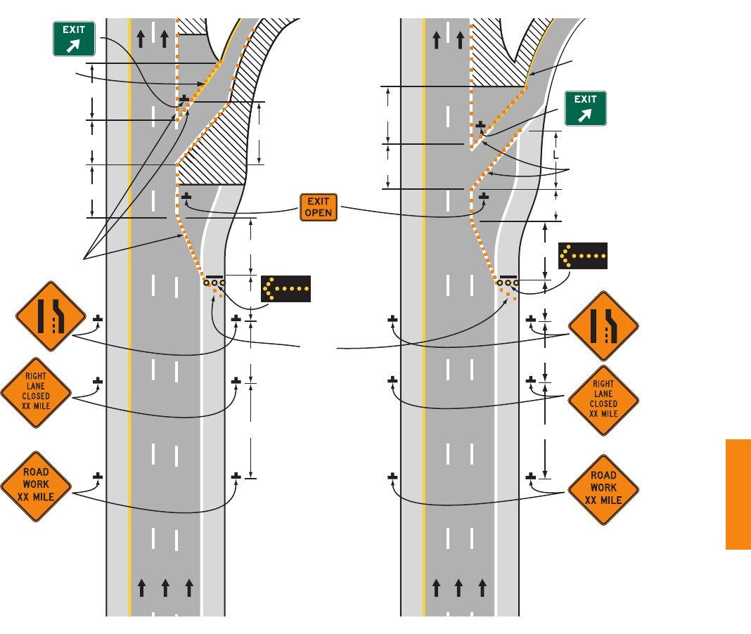
2009 Edition Page 717
Shoulder
taper
Note: See Tables 6H-2 and
6H-3 for the meaning
of the symbols and/or
letter codes used in
this figure.
Temporary white
edge lines
Typical Application 42
100 ft
1,000 ft
Temporary
yellow
edge line
L
100 ft
(optional)
L
A
B
C
L
A
B
C
1,000 ft
Temporary white
edge lines
Temporary
yellow
edge line
L
L
Figure 6H-42. Work in the Vicinity of an Exit Ramp (TA-42)
December 2009 Sect. 6H.01

Page 718 2009 Edition
Notes for Figure 6H-43—Typical Application 43
Partial Exit Ramp Closure
Guidance:
1. Truck off-tracking should be considered when determining whether the minimum lane width of 10 feet is
adequate (see Section 6G.08).
Sect. 6H.01 December 2009

2009 Edition Page 719
B
A
10 ft MIN.
500 ft
Note: See Tables 6H-2 and 6H-3 for the
meaning of the symbols and/or
letter codes used in this figure.
Typical Application 43
Figure 6H-43. Partial Exit Ramp Closure (TA-43)
December 2009 Sect. 6H.01

Page 720 2009 Edition
Notes for Figure 6H-44—Typical Application 44
Work in the Vicinity of an Entrance Ramp
Guidance:
1. An acceleration lane of sufcient length should be provided whenever possible as shown on the left
diagram.
Standard:
2. For the information shown on the diagram on the right-hand side of the typical application, where
inadequate acceleration distance exists for the temporary entrance, the YIELD sign shall be
replaced with STOP signs (one on each side of the approach).
Guidance:
3. When used, the YIELD or STOP sign should be located so that ramp vehicular trafc has adequate sight
distance of oncoming mainline vehicular trafc to select an acceptable gap in the mainline vehicular
trafc ow, but should not be located so far forward that motorists will be encouraged to stop in the path
of the mainline trafc. Also, a longer acceleration lane should be provided beyond the sign to reduce the
gap size needed. If insufcient gaps are available, consideration should be given to closing the ramp.
4. Where STOP signs are used, a temporary stop line should be placed across the ramp at the desired
stop location.
5. The mainline merging taper with the arrow board at its starting point should be located sufciently
in advance so that the arrow board is not confusing to drivers on the entrance ramp, and so that
the mainline merging vehicular trafc from the lane closure has the opportunity to stabilize before
encountering the vehicular trafc merging from the ramp.
6. If the ramp curves sharply to the right, warning signs with advisory speeds located in advance of the
entrance terminal should be placed in pairs (one on each side of the ramp).
Option:
7. A Stop Beacon (see Section 4L.05) or a Type B high-intensity warning asher with a red lens may be
placed above the STOP sign.
8. Where the acceleration distance is signicantly reduced, a supplemental plaque may be placed below the
Yield Ahead sign reading NO MERGE AREA.
Standard:
9. An arrow board shall be used when a freeway lane is closed. When more than one freeway lane is
closed, a separate arrow board shall be used for each closed lane.
Sect. 6H.01 December 2009

2009 Edition Page 721
Temporary yellow
edge line
Temporary yellow
edge line
Note: See Tables 6H-2 and
6H-3 for the meaning
of the symbols and/or
letter codes used in
this figure.
Typical Application 44
L
Temporary white
edge line
Shoulder
taper
(optional)
A
L
B
C
A - ADDED LANE B - MERGE REQUIRED
A
L
B
C
500 ft
500 ft
500 ft
Figure 6H-44. Work in the Vicinity of an Entrance Ramp (TA-44)
December 2009 Sect. 6H.01

Page 722 2009 Edition
Notes for Figure 6H-45—Typical Application 45
Temporary Reversible Lane Using Movable Barriers
Support:
1. This application addresses one of several uses for movable barriers (see Section 6F.85) in highway work
zones. In this example, one side of a 6-lane divided highway is closed to perform the work operation,
and vehicular trafc is carried in both directions on the remaining 3-lane roadway by means of a median
crossover.
To accommodate unbalanced peak-period vehicular trafc volumes, the direction of travel in the center
lane is switched to the direction having the greater volume, with the transfer typically being made twice
daily. Thus, there are four vehicular trafc phases described as follows:
a. Phase A—two travel lanes northbound and one lane southbound;
b. Transition A to B—one travel lane in each direction;
c. Phase B—one travel lane northbound and two lanes southbound; and
d. Transition B to A—one travel lane in each direction.
The typical application on the left illustrates the placement of devices during Phase A. The typical
application on the right shows conditions during the transition (Transition A to B) from Phase A to Phase B.
Guidance:
2. For the reversible-lane situation depicted, the ends of the movable barrier should terminate in a
protected area or a crash cushion should be provided. During Phase A, the transfer vehicle should
be parked behind the downstream end of the movable barrier for southbound trafc as shown in the
typical application on the left. During Phase B, the transfer vehicle should be parked behind between
the downstream ends of the movable barriers at the north end of the TTC zone as shown in the typical
application on the right.
The transition shift from Phase A to B should be as follows:
a. Change the signs in the northbound advance warning area and transition area from a LEFT
LANE CLOSED AHEAD to a 2 LEFT LANES CLOSED AHEAD. Change the mode of the second
northbound arrow board from Caution to Right Arrow.
b. Place channelizing devices to close the northbound center lane.
c. Move the transfer vehicle from south to north to shift the movable barrier from the west side to the
east side of the reversible lane.
d. Remove the channelizing devices closing the southbound center lane.
e. Change the signs in the southbound transition area and advance warning area from a 2 LEFT
LANES CLOSED AHEAD to a LEFT LANE CLOSED AHEAD. Change the mode of the second
southbound arrow board from Right Arrow to Caution.
3. Where the lane to be opened and closed is an exterior lane (adjacent to the edge of the traveled way or
the work space), the lane closure should begin by closing the lane with channelizing devices placed along
a merging taper using the same information employed for a stationary lane closure. The lane closure
should then be extended with the movable-barrier transfer vehicle moving with vehicular trafc. When
opening the lane, the transfer vehicle should travel against vehicular trafc. The merging taper should
be removed in a method similar to a stationary lane closure.
Option:
4. The procedure may be used during a peak period of vehicular trafc and then changed to provide two
lanes in the other direction for the other peak.
5. A longitudinal buffer space may be used in the activity area to separate opposing vehicular trafc.
6. A work vehicle or a shadow vehicle may be equipped with a truck-mounted attenuator.
Standard:
7. An arrow board shall be used when a freeway lane is closed. When more than one freeway lane is
closed, a separate arrow board shall be used for each closed lane.
Sect. 6H.01 December 2009

2009 Edition Page 723
Note: See Tables 6H-2 and 6H-3 for the meaning of the symbols and/or letter codes used in this figure.
Although leader lines point to the signs on the right-hand side of the roadway, most of these signs
should be installed on both sides of the roadway.
Typical Application 45
Figure 6H-45. Temporary Reversible Lane Using Movable Barriers (TA-45)
Buffer space
(optional)
TRANSITION FROM A TO B
PHASE A
Movable barrier
A
L
B
C
L
2L
A
Buffer space
(optional)
A
L
B
C
L
2L
A
Parking location
for transfer vehicle
during Phase A
A
B
C
L
1/2 L
A
L
2L
Movable barrier
Transfer
vehicle
1/2 L
1/2 L MIN.
Parking location
for transfer vehicle
during Phase B
Movable
attenuator
Parking location
for transfer vehicle
during Phase B
Movable
attenuator
B
C
L
A
December 2009 Sect. 6H.01

Page 724 2009 Edition
Notes for Figure 6H-46—Typical Application 46
Work in the Vicinity of a Grade Crossing
Guidance:
1. When grade crossings exist either within or in the vicinity of roadway work activities, extra care should
be taken to minimize the probability of conditions being created, by lane restrictions, agging, or other
operations, where vehicles might be stopped within the grade crossing, considered as being 15 feet on
either side of the closest and farthest rail.
Standard:
2. If the queuing of vehicles across active rail tracks cannot be avoided, a uniformed law enforcement
ofcer or agger shall be provided at the grade crossing to prevent vehicles from stopping within
the grade crossing (as described in Note 1), even if automatic warning devices are in place.
Guidance:
3. Early coordination with the railroad company or light rail transit agency should occur before work
starts.
4. In the example depicted, the buffer space of the activity area should be extended upstream of the grade
crossing (as shown) so that a queue created by the agging operation will not extend across the grade
crossing.
5. The DO NOT STOP ON TRACKS sign should be used on all approaches to a grade crossing within the
limits of a TTC zone.
Option:
6. Flashing warning lights and/or ags may be used to call attention to the advance warning signs.
7. A BE PREPARED TO STOP sign may be added to the sign series.
Guidance:
8. When used, the BE PREPARED TO STOP sign should be located before the Flagger symbol sign.
Standard:
9. At night, agger stations shall be illuminated, except in emergencies.
Sect. 6H.01 December 2009

2009 Edition Page 725
Note: See Tables 6H-2 and
6H-3 for the meaning
of the symbols and/or
letter codes used in
this figure.
(optional)
Typical Application 46
(optional)
A
B
C
50 to 100 ft
Extended buffer space
Two-way
traffic taper
50 to 100 ft
A
B
C
Figure 6H-46. Work in the Vicinity of a Grade Crossing (TA-46)
December 2009 Sect. 6H.01

Page 726 2009 Edition
CHAPTER 6I. CONTROL OF TRAFFIC THROUGH TRAFFIC
INCIDENT MANAGEMENT AREAS
Section 6I.01 General
Support:
01 The National Incident Management System (NIMS) requires the use of the Incident Command System (ICS)
at trafc incident management scenes.
02 A trafc incident is an emergency road user occurrence, a natural disaster, or other unplanned event that
affects or impedes the normal ow of trafc.
03 A trafc incident management area is an area of a highway where temporary trafc controls are installed,
as authorized by a public authority or the ofcial having jurisdiction of the roadway, in response to a road user
incident, natural disaster, hazardous material spill, or other unplanned incident. It is a type of TTC zone and
extends from the rst warning device (such as a sign, light, or cone) to the last TTC device or to a point where
vehicles return to the original lane alignment and are clear of the incident.
04 Trafc incidents can be divided into three general classes of duration, each of which has unique trafc control
characteristics and needs. These classes are:
A. Major—expected duration of more than 2 hours,
B. Intermediate—expected duration of 30 minutes to 2 hours, and
C. Minor—expected duration under 30 minutes.
05 The primary functions of TTC at a trafc incident management area are to inform road users of the incident
and to provide guidance information on the path to follow through the incident area. Alerting road users and
establishing a well dened path to guide road users through the incident area will serve to protect the incident
responders and those involved in working at the incident scene and will aid in moving road users expeditiously
past or around the trafc incident, will reduce the likelihood of secondary trafc crashes, and will preclude
unnecessary use of the surrounding local road system. Examples include a stalled vehicle blocking a lane, a trafc
crash blocking the traveled way, a hazardous material spill along a highway, and natural disasters such as oods
and severe storm damage.
Guidance:
06 In order to reduce response time for trafc incidents, highway agencies, appropriate public safety agencies
(law enforcement, re and rescue, emergency communications, emergency medical, and other emergency
management), and private sector responders (towing and recovery and hazardous materials contractors) should
mutually plan for occurrences of trafc incidents along the major and heavily traveled highway and street
system.
07 On-scene responder organizations should train their personnel in TTC practices for accomplishing their
tasks in and near trafc and in the requirements for trafc incident management contained in this Manual.
On-scene responders should take measures to move the incident off the traveled roadway or to provide for
appropriate warning. All on-scene responders and news media personnel should constantly be aware of their
visibility to oncoming trafc and wear high-visibility apparel.
08 Emergency vehicles should be safe-positioned (see denition in Section 1A.13) such that trafc ow through
the incident scene is optimized. All emergency vehicles that subsequently arrive should be positioned in a
manner that does not interfere with the established temporary trafc ow.
09 Responders arriving at a trafc incident should estimate the magnitude of the trafc incident, the expected
time duration of the trafc incident, and the expected vehicle queue length, and then should set up the
appropriate temporary trafc controls for these estimates.
Option:
10 Warning and guide signs used for TTC trafc incident management situations may have a black legend and
border on a uorescent pink background (see Figure 6I-1).
Support:
11 While some trafc incidents might be anticipated and planned for, emergencies and disasters might pose more
severe and unpredictable problems. The ability to quickly install proper temporary trafc controls might greatly
reduce the effects of an incident, such as secondary crashes or excessive trafc delays. An essential part of re,
rescue, spill clean-up, highway agency, and enforcement activities is the proper control of road users through the
trafc incident management area in order to protect responders, victims, and other personnel at the site. These
operations might need corroborating legislative authority for the implementation and enforcement of appropriate
road user regulations, parking controls, and speed zoning. It is desirable for these statutes to provide sufcient
exibility in the authority for, and implementation of, TTC to respond to the needs of changing conditions found
in trafc incident management areas.
Sect. 6I.01 December 2009

2009 Edition Page 727
Option:
12 For trafc incidents, particularly those of an emergency nature, TTC devices on hand may be used for the
initial response as long as they do not themselves create unnecessary additional hazards.
Section 6I.02 Major Trafc Incidents
Support:
01 Major trafc incidents are typically trafc incidents involving hazardous materials, fatal trafc crashes
involving numerous vehicles, and other natural or man-made disasters. These trafc incidents typically involve
closing all or part of a roadway facility for a period exceeding 2 hours.
Guidance:
02 If the trafc incident is anticipated to last more than 24 hours, applicable procedures and devices set forth
in other Chapters of Part 6 should be used.
Support:
03 A road closure can be caused by a trafc incident such as a road user crash that blocks the traveled way. Road
users are usually diverted through lane shifts or detoured around the trafc incident and back to the original
roadway. A combination of trafc engineering and enforcement preparations is needed to determine the detour
route, and to install, maintain or operate, and then to remove the necessary trafc control devices when the detour
is terminated. Large trucks are a signicant concern in such a detour, especially when detouring them from a
controlled-access roadway onto local or arterial streets.
04 During trafc incidents, large trucks might need to follow a route separate from that of automobiles because
of bridge, weight, clearance, or geometric restrictions. Also, vehicles carrying hazardous material might need to
follow a different route from other vehicles.
05 Some trafc incidents such as hazardous material spills might require closure of an entire highway. Through
road users must have adequate guidance around the trafc incident. Maintaining good public relations is desirable.
The cooperation of the news media in publicizing the existence of, and reasons for, trafc incident management
areas and their TTC can be of great assistance in keeping road users and the general public well informed.
06 The establishment, maintenance, and prompt removal of lane diversions can be effectively managed by
interagency planning that includes representatives of highway and public safety agencies.
Guidance:
07 All trafc control devices needed to set up the TTC at a trafc incident should be available so that they can
be readily deployed for all major trafc incidents. The TTC should include the proper trafc diversions, tapered
lane closures, and upstream warning devices to alert trafc approaching the queue and to encourage early
diversion to an appropriate alternative route.
08 Attention should be paid to the upstream end of the trafc queue such that warning is given to road users
approaching the back of the queue.
09 If manual trafc control is needed, it should be provided by qualied aggers or uniformed law
enforcement ofcers.
M4-8a M4-10M4-9
W9-3W3-4
E5-2a
W4-2
Figure 6I-1. Examples of Traffic Incident Management Area Signs
December 2009 Sect. 6I.01 to 6I.02

Page 728 2009 Edition
Option:
10 If aggers are used to provide trafc control for an incident management situation, the aggers may use
appropriate trafc control devices that are readily available or that can be brought to the trafc incident scene
on short notice.
Guidance:
11 When light sticks or ares are used to establish the initial trafc control at incident scenes, channelizing
devices (see Section 6F.63) should be installed as soon thereafter as practical.
Option:
12 The light sticks or ares may remain in place if they are being used to supplement the channelizing devices.
Guidance:
13 The light sticks, ares, and channelizing devices should be removed after the incident is terminated.
Section 6I.03 Intermediate Trafc Incidents
Support:
01 Intermediate trafc incidents typically affect travel lanes for a time period of 30 minutes to 2 hours, and
usually require trafc control on the scene to divert road users past the blockage. Full roadway closures might
be needed for short periods during trafc incident clearance to allow trafc incident responders to accomplish
their tasks.
02 The establishment, maintenance, and prompt removal of lane diversions can be effectively managed by
interagency planning that includes representatives of highway and public safety agencies.
Guidance:
03 All trafc control devices needed to set up the TTC at a trafc incident should be available so that they can
be readily deployed for intermediate trafc incidents. The TTC should include the proper trafc diversions,
tapered lane closures, and upstream warning devices to alert trafc approaching the queue and to encourage
early diversion to an appropriate alternative route.
04 Attention should be paid to the upstream end of the trafc queue such that warning is given to road users
approaching the back of the queue.
05 If manual trafc control is needed, it should be provided by qualied aggers or uniformed law
enforcement ofcers.
Option:
06 If aggers are used to provide trafc control for an incident management situation, the aggers may use
appropriate trafc control devices that are readily available or that can be brought to the trafc incident scene on
short notice.
Guidance:
07 When light sticks or ares are used to establish the initial trafc control at incident scenes, channelizing
devices (see Section 6F.63) should be installed as soon thereafter as practical.
Option:
08 The light sticks or ares may remain in place if they are being used to supplement the channelizing devices.
Guidance:
09 The light sticks, ares, and channelizing devices should be removed after the incident is terminated.
Section 6I.04 Minor Trafc Incidents
Support:
01 Minor trafc incidents are typically disabled vehicles and minor crashes that result in lane closures of less than
30 minutes. On-scene responders are typically law enforcement and towing companies, and occasionally highway
agency service patrol vehicles.
02 Diversion of trafc into other lanes is often not needed or is needed only briey. It is not generally possible
or practical to set up a lane closure with trafc control devices for a minor trafc incident. Trafc control is the
responsibility of on-scene responders.
Guidance:
03 When a minor trafc incident blocks a travel lane, it should be removed from that lane to the shoulder as
quickly as possible.
Sect. 6I.02 to 6I.04 December 2009

2009 Edition Page 729
Section 6I.05 Use of Emergency-Vehicle Lighting
Support:
01 The use of emergency-vehicle lighting (such as high-intensity rotating, ashing, oscillating, or strobe lights) is
essential, especially in the initial stages of a trafc incident, for the safety of emergency responders and persons
involved in the trafc incident, as well as road users approaching the trafc incident. Emergency-vehicle lighting,
however, provides warning only and provides no effective trafc control. The use of too many lights at an
incident scene can be distracting and can create confusion for approaching road users, especially at night. Road
users approaching the trafc incident from the opposite direction on a divided facility are often distracted by
emergency-vehicle lighting and slow their vehicles to look at the trafc incident posing a hazard to themselves and
others traveling in their direction.
02 The use of emergency-vehicle lighting can be reduced if good trafc control has been established at a trafc
incident scene. This is especially true for major trafc incidents that might involve a number of emergency
vehicles. If good trafc control is established through placement of advanced warning signs and trafc control
devices to divert or detour trafc, then public safety agencies can perform their tasks on scene with minimal
emergency-vehicle lighting.
Guidance:
03 Public safety agencies should examine their policies on the use of emergency-vehicle lighting, especially after
a trafc incident scene is secured, with the intent of reducing the use of this lighting as much as possible while
not endangering those at the scene. Special consideration should be given to reducing or extinguishing forward
facing emergency-vehicle lighting, especially on divided roadways, to reduce distractions to oncoming road users.
04 Because the glare from oodlights or vehicle headlights can impair the nighttime vision of approaching road
users, any oodlights or vehicle headlights that are not needed for illumination, or to provide notice to other road
users of an incident response vehicle being in an unexpected location, should be turned off at night.
December 2009 Sect. 6I.05

Page 730 2009 Edition
Sect. 6I.05 December 2009
(This page left intentionally blank)
